54
3 SIGNALS AND WIRING
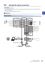
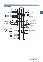
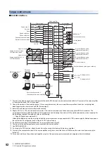
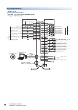
3.2 Example I/O signal connections
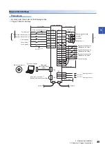
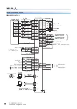
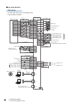
MR-J5W_-_G_
Precautions
• In the torque control mode, EM2 functions the same as EM1.
Sink I/O interface
1
LSP-C
DOG-B
SD
23
10
CN3
19
*2
LBR-B
14
LG
11
CALM
12
25
MBR-B
13
MBR-C
3
LA-A
16
LAR-A
4
LB-A
17
LBR-A
5
LA-B
18
LAR-B
CN3
6
LB-B
*16
*10
DICOM
EM2
7
LSP-A
8
LSN-A
9
DOG-A
20
LSP-B
21
LSN-B
22
MBR-A
RA1
RA2
RA3
RA4
RA5
2
LSN-C
15
DOG-C
*14
24
*8
*9
26
DOCOM
CN6
CN5
MO1
MO2
3
LG
1
2
CN1A
CN1B
CN8
MR-J3USBCBL3M
*1
MR Configurator2
*5
+
10 m or less
10 m or less
Main circuit power supply
*11
Servo amplifier
24 V DC
*6
24 V DC
*6
Forced stop 2
*3*4
AND malfunction
*7
Forward rotation stroke end for A-axis
Electromagnetic brake
interlock for A-axis
Reverse rotation stroke end for A-axis
Proximity dog for A-axis
Electromagnetic brake
interlock for B-axis
Forward rotation stroke end for B-axis
Electromagnetic brake
interlock for C-axis
*13
Reverse rotation stroke end for B-axis
Proximity dog for B-axis
Forward rotation stroke end for C-axis
Reverse rotation stroke end for C-axis
Proximity dog for C-axis
Encoder A-phase pulse for A-axis
(differential line driver)
*15
Encoder B-phase pulse for A-axis
(differential line driver)
*15
Encoder A-phase pulse for B-axis
(differential line driver)
*15
Encoder B-phase pulse for B-axis
(differential line driver)
*15
Control common
USB cable
(option)
Analog monitor 1
Analog monitor 2
2 m or less
Short-circuit connector
*12
(Packed with the servo amplifier)
Personal computer
Plate
Network
Network
± 10 V DC
± 10 V DC
Summary of Contents for MELSERVO-J5 MR-J5-G Series
Page 2: ......
Page 473: ...12 USING A FULLY CLOSED LOOP SYSTEM 12 7 Absolute position detection system 471 12 MEMO ...
Page 477: ......

