


3 SIGNALS AND WIRING
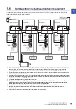
3.1 Connection example of power circuit
21
3
The following items are the same as those for MR-J4-_B_(-RJ). Refer to the section of the detailed explanation field for
details. "MR-J4-_B_" means "MR-J4-_B_(-RJ) Servo Amplifier Instruction Manual". "MR-J4-DU_B_" means "MR-CV_/MR-
CR55K_/MR-J4-DU_(-RJ) Instruction Manual".
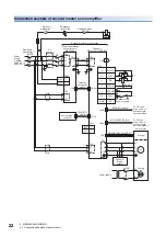
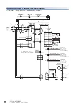
3.1
Connection example of power circuit
For drive units, EM2 has the same function as EM1 in the torque control mode.
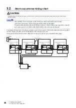
Even if alarm has occurred, do not switch off the control circuit power supply. When the control circuit power
supply is shut off, an optical module does not operate, and optical transmission of SSCNET III/H
communication is interrupted. Therefore, the next servo amplifiers and drive units show "AA" on the display
and shut off the base circuit, stopping the servo motor with the dynamic brake.
For the magnetic contactor control connector (CN23), refer to section 3.3 in "MR-CV_/MR-CR55K_/MR-J4-
DU_(-RJ) Instruction Manual".
If the control axis No. is not be set correctly, or an SSCNET III cable is not be connected, the relay may switch
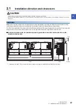
on and off repeatedly. Check the control axis No. setting and SSCNET III cable connection.
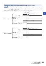
Item
Detailed explanation
I/O signal connection example
MR-J4-_B_ section 3.2
Explanation of power supply system
MR-J4-DU_B_ sections 3.3 and 5.2
Connectors and pin assignment
MR-J4-DU_B_ sections 3.3 and 5.2
Signal (device) explanations
MR-J4-_B_ section 3.5
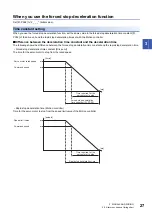
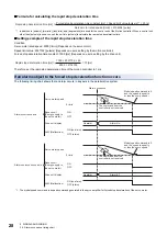
Forced stop deceleration function
MR-J4-_B_ section 3.6
Interface
MR-J4-DU_B_ section 3.3
SSCNET III cable connection
MR-J4-_B_ section 3.9
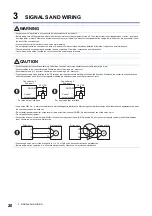
WARNING
• Insulate the connections of the power supply terminals. Otherwise, an electric shock may occur.
CAUTION
• Be sure to connect a magnetic contactor between the power supply and the main circuit power supply (L1/L2/L3) of the power regeneration converter unit, in
order to configure a circuit that shuts off the power supply by the power regeneration converter unit. If a magnetic contactor is not connected, continuous flow
of a large current may cause a fire when the power regeneration converter unit or the drive unit malfunctions.
• Use ALM (Malfunction) to shut the power off. Not doing so may cause a fire when the power regeneration converter unit malfunctions and causes the AC
reactor to overheat.
• The power regeneration converter unit has a built-in surge absorber (varistor) to reduce exogenous noise and to suppress lightning surge. Exogenous noise
or lightning surge deteriorates the varistor characteristics, and the varistor may be damaged. To prevent a fire, use a molded-case circuit breaker or fuse for
the input power supply.
• Check the power regeneration converter unit model, and then input proper voltage to the power regeneration converter unit power supply. If input voltage
exceeds the upper limit, the power regeneration converter unit and the drive unit will break down.
Summary of Contents for Melservo-J4 MR-J4-DU*B4-RJ100 Series
Page 2: ......
Page 75: ...9 USING STO FUNCTION 73 9 MEMO ...
Page 81: ...11 APPENDIX 11 1 Analog monitor 79 11 MEMO ...
Page 85: ......


