


481
CHAPTER 11 MANUAL CONTROL
11
11.
2 JO
G
O
per
at
ion
11.2
JOG Operation
11.2.1
Outline of JOG operation
Use the hardware stroke limit function when carrying out JOG operation near the upper or lower limits. (
Section 12.4.4)
If the hardware stroke limit function is not used, the workpiece may exceed the movement range, and an accident may
result.
(1) JOG operation
In JOG operation, the Forward run JOG start signal [Y8, YA, YC, YE] or Reverse run JOG start signal [Y9, YB,
YD, YF] turns ON, causing pulses to be output to the drive unit from the LD75 while the signal is ON. The
workpiece is then moved in the designated direction.
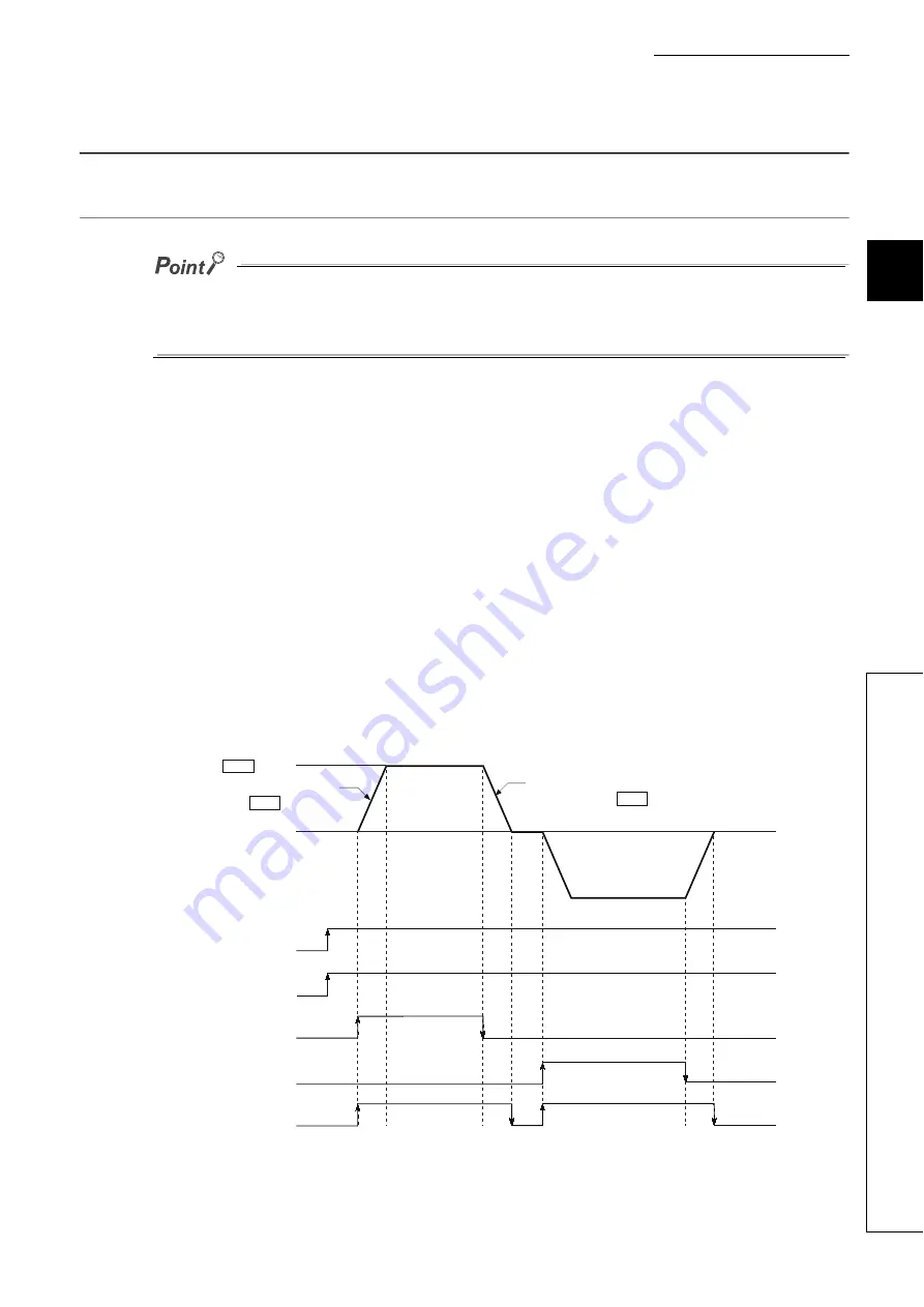
The following shows examples of JOG operation.
1.
When the JOG start signal turns ON, acceleration begins in the direction designated by the JOG
start signal, and continues for the acceleration time designated in "[Pr.32] JOG operation
acceleration time selection". At this time, the BUSY signal changes from OFF to ON.
2.
When the workpiece being accelerated reaches the speed set in "[Cd.17] JOG speed", the
movement continues at this speed. The constant speed movement takes place at 2 and 3.
3.
When the JOG start signal is turned OFF, deceleration begins from the speed set in "[Cd.17] JOG
speed", and continues for the deceleration time designated in "[Pr.33] JOG operation deceleration
time selection".
4.
The operation stops when the speed becomes "0". At this time, the BUSY signal changes from ON
to OFF.
OFF
ON
OFF
ON
OFF
ON
OFF
ON
Forward
JOG operation
Reverse JOG operation
JOG
speed
ON
OFF
1
2
3
4
Cd.17
Pr.32
Pr.33
PLC READY signal
[Y0]
LD75 READY signal
[X0]
Forward run JOG start signal
[Y8, YA, YC, YE]
Reverse run JOG start signal
[Y9, YB, YD, YF]
BUSY signal
[XC, XD, XE, XF]
Acceleration for the acceleration
time selected in
Deceleration for the deceleration
time selected in
Summary of Contents for MELSEC-L LD75D
Page 2: ......
Page 11: ...9 Memo ...
Page 176: ...174 ...
Page 264: ...262 ...
Page 266: ...264 ...
Page 267: ...265 CHAPTER 6 PROGRAM USED FOR POSITIONING CONTROL 6 6 4 Positioning Program Examples ...
Page 268: ...266 ...
Page 269: ...267 CHAPTER 6 PROGRAM USED FOR POSITIONING CONTROL 6 6 4 Positioning Program Examples ...
Page 270: ...268 ...
Page 271: ...269 CHAPTER 6 PROGRAM USED FOR POSITIONING CONTROL 6 6 4 Positioning Program Examples ...
Page 272: ...270 Z ABRST1 instruction execution ...
Page 273: ...271 CHAPTER 6 PROGRAM USED FOR POSITIONING CONTROL 6 6 4 Positioning Program Examples ...
Page 278: ...276 ...
Page 279: ...277 CHAPTER 6 PROGRAM USED FOR POSITIONING CONTROL 6 6 4 Positioning Program Examples ...
Page 280: ...278 ...
Page 281: ...279 CHAPTER 6 PROGRAM USED FOR POSITIONING CONTROL 6 6 4 Positioning Program Examples ...
Page 282: ...280 ...
Page 283: ...281 CHAPTER 6 PROGRAM USED FOR POSITIONING CONTROL 6 6 4 Positioning Program Examples ...
Page 284: ...282 ...
Page 285: ...283 CHAPTER 6 PROGRAM USED FOR POSITIONING CONTROL 6 6 4 Positioning Program Examples ...
Page 286: ...284 ...
Page 287: ...285 CHAPTER 6 PROGRAM USED FOR POSITIONING CONTROL 6 6 4 Positioning Program Examples ...
Page 316: ...314 Memo ...
Page 685: ...683 APPENDICES A Appendix 1 Function Update Appendix 1 1 Function comparison Memo ...
Page 738: ...736 Memo ...
Page 817: ......


