


39 PRECAUTIONS ON PROGRAMMING
39.4 Precautions on Timers and Timer Function Blocks
693
39
39.4
Precautions on Timers and Timer Function Blocks
This section describes the precautions on timers and timer function blocks at system switching.
Current values at system switching
For the timer (T), retentive timer (ST), and a timer function block TIMER_
_M, the current values of the timers in the first scan
of the CPU module of the new control system will not be updated after system switching.
Timeout before system switching
Depending on the timing to perform system switching such as power-off, tracking transfer processing is suspended and
tracking data may not be reflected to the CPU module in the new control system. For the timer (T), retentive timer (ST), long
timer (LT), long retentive timer (LST), and timer function blocks TIMER_
_M, TP(_E), TON(_E), and TOF(_E), the timer
whose time has been up before system switching may go into the state in which no timeout has occurred in the first scan after
system switching.
When values are output (writing values to the buffer memory and the output (Y)) with a timer contact or an output variable, the
timer statues may go into the state in which no timeout has occurred as described above, causing chattering of the output.
To transfer data with modules or external devices using the output (Y) or buffer memory, a program may not properly function
due to chattering of output after the system switching. To output values (writing data to the buffer memory and the output (Y))
to modules or external devices with a timer contact or an output variable, consider the time taken for data to be transferred
from the CPU module in the control system to the CPU module in the standby system after the time is up.
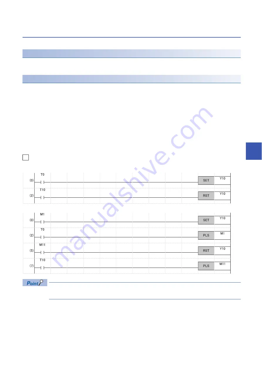
Ex.
Program that delays outputting values by one scan after the time of the timer (T) is up
In the CPU parameter, select "Transfer" (default setting) in "Signal Flow Memory Tracking Setting" of
"Redundant System Settings". (
Page 629 Tracking transfer setting for the signal flow memory)
[Without measures]
[With measures]
Summary of Contents for MELSEC iQ-R-R00CPU
Page 2: ......
Page 151: ...9 MONITOR FUNCTION 9 1 Real Time Monitor Function 149 9 MEMO ...
Page 323: ...18 SEQUENCE SCAN SYNCHRONIZATION SAMPLING FUNCTION 321 18 MEMO ...
Page 330: ...328 20 ROUTING SETTING 20 3 Precautions MEMO ...
Page 423: ...26 BASIC CONCEPT 26 8 State Transition of the Redundant System 421 26 MEMO ...
Page 1014: ...1012 APPX Appendix 15 Added and Enhanced Functions MEMO ...
Page 1027: ......


