


23 LATCH FUNCTION
23.1 Latch with Battery
393
23
Setting latch on labels
This section describes latch setting on labels.
Operating procedure
Clearing latch range data
Latch range data is cleared by either of the operations below. (
• Latch clear: Performed from the engineering tool. (
GX Works3 Operating Manual)
• Latch clear by program: Execute the RST instruction for latched devices, or clear by transferring K0 by using the MOV or
FMOV instruction.
Precautions
This section describes the precautions when using the latch function.
• When using a CPU module other than the R00CPU, R01CPU, and R02CPU, the data in a device/label within the latch
range is retained by using the battery on the CPU module unit. Therefore, data cannot be retained during power failure if
this battery runs out. Use the battery-less option cassette for retaining the data without a battery during power failure. (
Page 394 Latch with Battery-less Option Cassette)
• If the latch range and number of device points are modified by using parameters, latch is performed on the modified latch
range. However, if the value of the parameter setting the latch range is different between the previous and current
operations because the CPU module was powered off and on or is reset, and the latch range has been increased, the
device range in the increased portion is not latched.
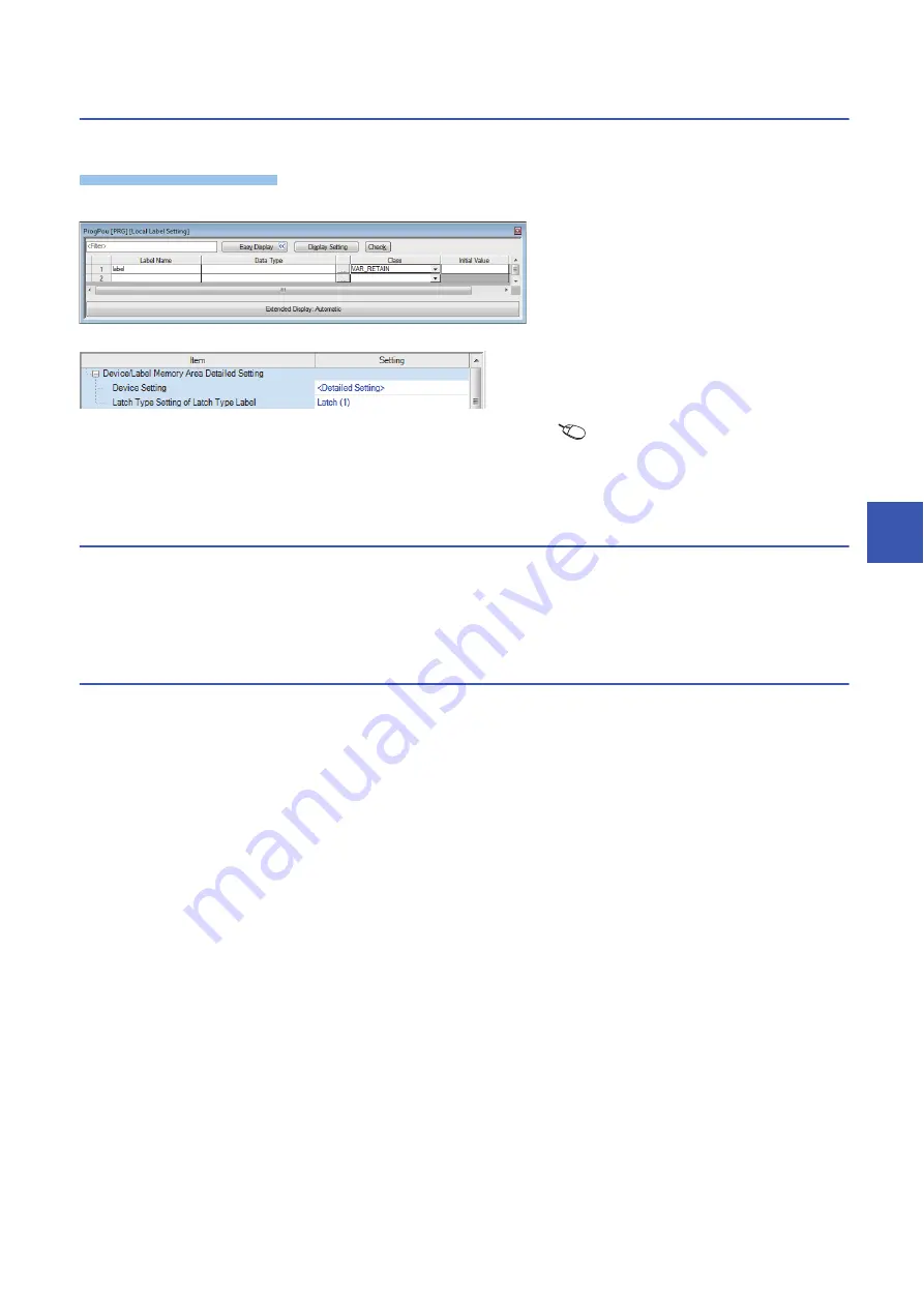
Label edit window
1.
In the label edit window, specify
"RETAIN" for label attribute.
"Device/Label Memory Area Detailed Setting" window
2.
There are two types of latch for labels:
latch (1) and latch (2). Select one. The
selected latch type is applied to labels of
all latch attributes.
[CPU Parameter]
[Memory/Device
Setting]
[Device/Label Memory Area
Detailed Setting]
[Latch Type Setting
of Latch Type Label]
Summary of Contents for MELSEC iQ-R-R00CPU
Page 2: ......
Page 151: ...9 MONITOR FUNCTION 9 1 Real Time Monitor Function 149 9 MEMO ...
Page 323: ...18 SEQUENCE SCAN SYNCHRONIZATION SAMPLING FUNCTION 321 18 MEMO ...
Page 330: ...328 20 ROUTING SETTING 20 3 Precautions MEMO ...
Page 423: ...26 BASIC CONCEPT 26 8 State Transition of the Redundant System 421 26 MEMO ...
Page 1014: ...1012 APPX Appendix 15 Added and Enhanced Functions MEMO ...
Page 1027: ......


