14 PROCEDURES BEFORE OPERATION
14.8 Setting Parameters
245
14
When setting parameters from the Module configuration diagram
"CPU parameter" and "module parameter" can be set from the module configuration diagram. The following shows how to set
them.
[Navigation]
[Module Configuration]
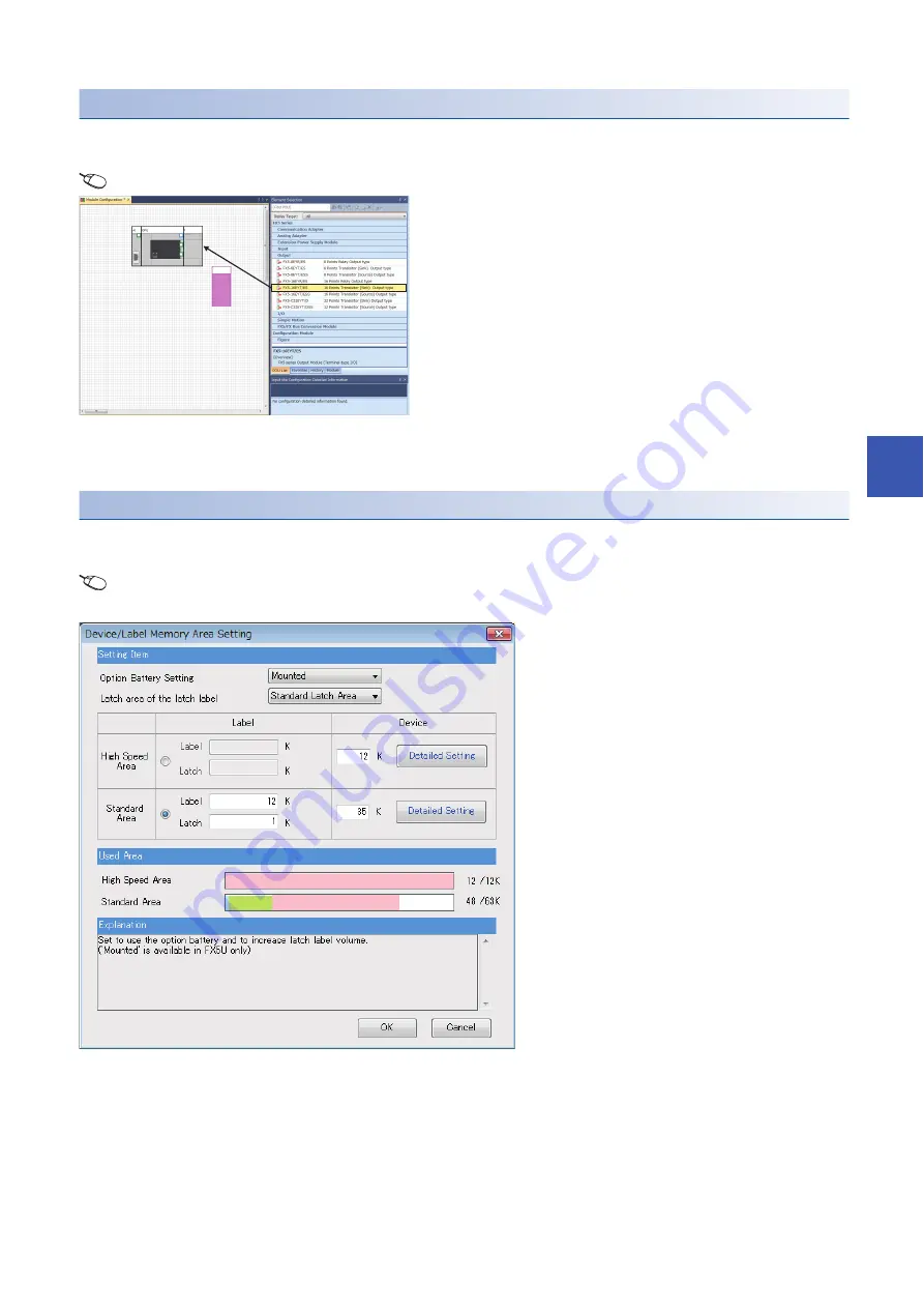
Setting an optional battery using the engineering tool
The following setting is required when the capacity of the latch device/latch label is increased using the optional battery.
Note that the battery does not back up the data when the following setting is not provided.
[Navigation]
[Parameter]
Module model name
[CPU Parameter]
[Memory/Device Setting]
[Device/Label
Memory Area Setting]
[Detailed Setting]
[Device/Label Memory Area Setting] window
Set the option battery setting to "Mounted" in Device/Label Memory Area Setting window.
1.
Drag each module to be used from the parts select
window to the module configuration diagram with the
mouse, and place the module to be coupled to the CPU
module on the diagram.
2.
Select [Edit]
[Parameter]
[Fix] on the menu bar.
3.
When module labels are prepared in the configured
modules, the window for adding module labels appears.
Click the [Yes] button.
4.
Open the parameter editor of each module by double-
clicking the module having parameters that can be set.
5.
Set parameters, and click the [Apply] button to close the
window.
Summary of Contents for MELSEC iQ-F FX5UC Series
Page 2: ......
Page 142: ...140 8 CONNECTOR CONVERSION MODULE PERFORMANCE SPECIFICATIONS 8 2 External Dimensions MEMO ...
Page 144: ...142 9 SD MEMORY CARD PERFORMANCE SPECIFICATIONS 9 2 Formatting MEMO ...
Page 146: ...144 10 BATTERY PERFORMANCE SPECIFICATIONS 10 2 Battery Life MEMO ...
Page 277: ...I 275 MEMO ...
Page 281: ......


