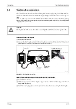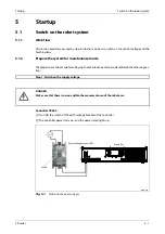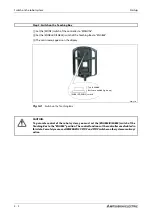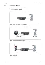
Mode changeover switch connection
Connection
4 - 18
4.5
Mode changeover switch connection
Connect the key switch of customer prepared and change the right of robot’s operation by switch op-
eration. The key switch can be installed in the operation panel of customer preparation.
Right of operation (mode):
AUTOMATIC. . . . . . . . . . . The operation from external equipment becomes available. Operation which
needs the right of operation from T/B cannot be performed. It is necessary to
set the parameter for the rights of operation to connection with external
equipment. Refer to the separate volume, "Instruction Manual/Detailed Ex-
planation of Functions and Operations" for detail.
MANUAL . . . . . . . . . . . . . . When T/B is available, only the operation from T/B becomes available. Oper-
ation which needs the right of operation from external equipment cannot be
performed.
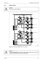
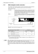
The mode changes by both opening or both closing between 21-5 pin and between 28-12 pin.
Maintain the current mode except it.
R002728E
Fig. 4-18:
Connection of the Mode changeover switch
Pin number and Function (Connector: CNUSR11)
Change mode
Pin-No.
Function
MANUAL
AUTOMATIC
21
1st line KEY input
Open
Close
5
Power 24 V of pin number 21
28
2nd line KEY input
Open
Close
12
Power 24 V of pin number 28
Tab. 4-3:
Function of the key switch interface
NOTE
The contact capacity of each input/output terminal is 24 V DC/100 mA. Don't connect the equip-
ment except for this range. The use exceeding contact capacity causes failure.
In the customer's system, do not ground the + side of 24 V power supply prepared by customer for
connect to the controller. (related with emergency stop and parallel input/output) If it connects
with the controller under the condition that the + side is grounded, it will lead to failure of control-
ler.
MODE
MANUAL
AUTOMATIC
Mode changeover
switch
CNUSR11 connector
Summary of Contents for MELFA RH-FRH-D
Page 2: ......
Page 4: ......
Page 6: ......
Page 16: ...Contents X ...
Page 22: ...Environmental conditions for operation Introduction 1 6 ...
Page 70: ...Grounding the robot system Installation 3 32 ...
Page 90: ...Teaching Box connection Connection 4 20 ...
Page 96: ...Switch on the robot system Startup 5 6 ...
Page 128: ...Dimensions Appendix A 18 ...
Page 130: ...A 20 Index Appendix ...
Page 131: ......
Page 132: ......
Page 133: ......
Page 134: ......
Page 135: ......
Page 136: ......
Page 137: ......
Page 138: ......
Page 139: ......
Page 140: ......
Page 141: ......
Page 142: ......
Page 143: ......
Page 144: ......
Page 145: ......
Page 146: ......
Page 147: ......
Page 148: ......
Page 149: ......
Page 150: ......
Page 151: ......
Page 152: ......
Page 153: ......
Page 154: ......
Page 155: ......
Page 156: ......
Page 157: ......
Page 158: ......
Page 159: ......
Page 160: ......
Page 161: ......
Page 162: ......
Page 163: ......
Page 164: ......
Page 165: ......

