


13. DEBUG
13.2 Debug Setting
13 - 3
9
HANDLING OF PO
WER WI
RI
N
G
AND SWIT
CH
10
UTIL
ITY FUNC
TION
11
DI
SPLA
Y
A
N
D
OP
ERA
T
IO
N
SE
TTI
N
GS
12
COMMUNICA
TION
INTE
RF
A
C
E
SE
TT
IN
G
13
DE
BUG
14
S
E
LF CHECK
15
D
A
TA
CONTROL
16
IN
ST
ALLA
TI
ON OF
COREOS,
B
O
OT
OS A
ND
ST
ANDA
RD MONI
TO
R OS
13.2 Debug Setting
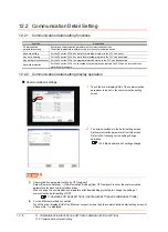
13.2.1 Q/L/QnA ladder monitor setting
Storage locations and others for data to be used for the ladder monitor function can be set.
Saving the ladder data cuts out the need for reading the ladder data from PLC CPU at the next GOT start-up, enabling to
start the ladder monitoring earlier.
Refer to the following manual for details of the ladder monitoring function.
GOT1000 Series Extended/Option Functions Manual for GT Works3
POINT
POINT
POINT
Ladder data to be saved
(1) The ladder data to be saved is used by the GOT to execute ladder monitoring.
The ladder data can be saved in the CF card with this function, however it cannot be copied in the PC to be
referred/edited with GX Developer, etc.
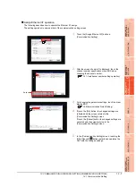
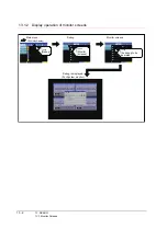
The name of the ladder data to be stored can be checked with the project information.
For how to check the name of ladder data, refer to the following.
Display operation of project information
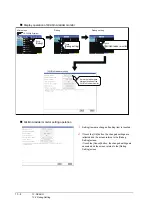
(2) The ladder data saved in the built-in flash memory and CF card or USB memory (file name: CIRDAT) can be
deleted by selecting [Project information] in [OS/project information] of [Data control].
Operation of project information
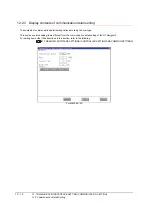
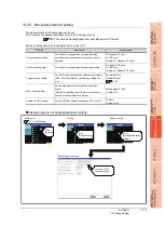
Function
Description
Setting range
Data save location
Select the ladder data storage location of the Q/L/QnA
ladder monitor.
C: Flash Memory/A: Built-in CF Card/Not store
<Default: C: Flash Memory>
Automatic program read
Whether to automatically read sequence program when
the ladder monitor starts from a touch switch or Advanced
Alarm Display can be selected.
YES/NO
<Default: YES>
Priority comment
If both Common comment and Each program comment
are set for the same device in a sequence program,
select either of the comments to be displayed in the
ladder monitor.
Common comment/Each program comment
<Default: Common comment>
Local device monitor
Select if monitoring local devices are executed or not
when monitoring devices with the ladder monitor.
(Applicable to only the MELSEC-Q series ladder
monitor)
YES/NO
<Default: NO>
Drive for device
comment
Select the drive to be used for reading comment data for
the ladder monitor.
A:Built-in CF card
<Default: A:Built-in CF card>
Comment setting
Select if the comment data used in the ladder monitor is
displayed/hidden.
Hide comment/Display comment/32-char comment
<Default: Hide comment>
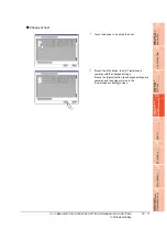
Setting to save ladders
Select if the ladder data of one connected device is
stored or the ladder data of multiple connected devices
is stored.
Save ladder programs/Save a ladder program
<Default: Save a ladder program>
Summary of Contents for GT16
Page 1: ......
Page 2: ......
Page 46: ...1 4 1 OVERVIEW 1 1 Features ...
Page 54: ...2 8 2 SYSTEM CONFIGURATION 2 2 System Equipment ...
Page 60: ...3 6 3 SPECIFICATIONS 3 4 Battery specifications ...
Page 72: ...5 8 5 UL cUL STANDARDS AND EMC DIRECTIVE 5 2 EMC Directive ...
Page 102: ...6 30 6 OPTION 6 7 Connector Conversion Box ...
Page 106: ...7 4 7 INSTALLATION 7 1 Installing Procedure ...
Page 110: ...8 4 8 COMMUNICATION CABLE 8 1 Overview of Communication Cable ...
Page 130: ...9 20 9 HANDLING OF POWER WIRING AND SWITCH 9 4 Switch Wiring ...
Page 142: ...10 12 10 UTILITY FUNCTION 10 3 Utility Display ...
Page 184: ...11 42 11 DISPLAY AND OPERATION SETTINGS GOT SET UP 11 4 Maintenance Function ...
Page 202: ...12 18 12 COMMUNICATION INTERFACE SETTING COMMUNICATION SETTING 12 3 Ethernet Setting ...
Page 226: ...13 24 13 DEBUG 13 3 Memory Data Control ...
Page 248: ...14 22 14 SELF CHECK 14 2 Batch Self Check ...
Page 350: ...15 102 15 DATA CONTROL 15 3 OS Project Information ...
Page 410: ...19 22 19 TROUBLESHOOTING 19 2 Error Message and System Alarm ...
Page 418: ...App 8 APPENDICES Appendix 3 Transportation Precautions ...
Page 422: ...REVISIONS 4 ...
Page 425: ......
Page 426: ......
Page 427: ......
Page 428: ......
Page 470: ......
Page 510: ...21 22 21 COMPUTER LINK CONNECTION 21 6 Precautions ...
Page 568: ...22 58 22 ETHERNET CONNECTION 22 5 Precautions ...
Page 584: ......
Page 626: ...25 14 25 SERVO AMPLIFIER CONNECTION 25 7 Precautions ...
Page 632: ...26 6 26 ROBOT CONTROLLER CONNECTION 26 6 Precautions ...
Page 647: ...MULTIPLE GOT CONNECTIONS 29 GOT MULTI DROP CONNECTION 29 1 ...
Page 648: ......
Page 659: ...MULTI CHANNEL FUNCTION 30 MULTI CHANNEL FUNCTION 30 1 ...
Page 660: ......
Page 675: ...FA TRANSPARENT FUNCTION 31 FA TRANSPARENT FUNCTION 31 1 ...
Page 676: ......
Page 742: ...31 66 31 FA TRANSPARENT FUNCTION 31 7 Precautions ...
Page 744: ......
Page 766: ...32 22 32 CONNECTION TO IAI ROBOT CONTROLLER 32 7 Precautions ...
Page 802: ...34 10 34 CONNECTION TO OMRON TEMPERATURE CONTROLLER 34 7 Precautions ...
Page 834: ...36 18 36 CONNECTION TO KOYO EI PLC 36 6 Device Range that Can Be Set ...
Page 858: ...38 12 38 CONNECTION TO SHARP PLC 38 6 Device Range that Can Be Set ...
Page 868: ...39 10 39 CONNECTION TO SHINKO TECHNOS INDICATING CONTROLLER 39 7 Precautions ...
Page 902: ...42 6 42 CONNECTION TO TOSHIBA MACHINE PLC 42 6 Device Range that Can Be Set ...
Page 908: ...43 6 43 CONNECTION TO PANASONIC SERVO AMPLIFIER 43 7 Precautions ...
Page 970: ...48 12 48 CONNECTION TO FUJI TEMPERATURE CONTROLLER 48 7 Precautions ...
Page 1052: ...52 26 52 CONNECTION TO AZBIL CONTROL EQUIPMENT 52 7 Precautions ...
Page 1102: ...55 14 55 CONNECTION TO GE PLC 55 7 Precautions ...
Page 1114: ...57 4 57 CONNECTION TO SICK SAFETY CONTROLLER 57 5 Device Range that Can Be Set ...
Page 1128: ...59 2 59 CONNECTION TO HIRATA CORPORATION HNC CONTROLLER ...
Page 1130: ...60 2 60 CONNECTION TO MURATEC CONTROLLER ...
Page 1132: ......
Page 1270: ...62 68 62 MICROCOMPUTER CONNECTION ETHERNET 62 8 Precautions ...
Page 1271: ...MODBUS CONNECTIONS 63 MODBUS R RTU CONNECTION 63 1 64 MODBUS R TCP CONNECTION 64 1 ...
Page 1272: ......
Page 1292: ...64 12 64 MODBUS R TCP CONNECTION 64 7 Precautions ...
Page 1293: ...CONNECTIONS TO PERIPHERAL EQUIPMENT 65 VNC R SERVER CONNECTION 65 1 ...
Page 1294: ......
Page 1298: ...65 4 65 VNC R SERVER CONNECTION 65 4 Setting in Personal Computer ...
Page 1302: ...REVISIONS 4 ...
Page 1305: ......
Page 1306: ......


