


11 - 34
11. DISPLAY AND OPERATION SETTINGS (GOT SET UP)
11.4 Maintenance Function
11.4 Maintenance Function
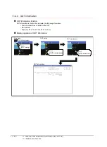
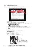
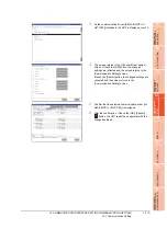
11.4.1 Maintenance time setting
Energization time, touch count and writing times used as a standard for the maintenance time are set.
For using the maintenance time notification, a battery is required.
Refer to the following for the details of battery.
Function of the maintenance timing setting
For using the maintenance time notification, a battery is required.
When setting the time or count to notify the maintenance time, refer to the life described in “3.2Performance
Specifications“as a guide.
The maintenance time notification is output by the following two methods.
• Outputs to GOT special register (GS680).
• Outputs as system alarm
For details of the GOT special register and system alarm, refer to the following.
GT Designer3 Version1 Screen Design Manual (Fundamentals)
POINT
POINT
POINT
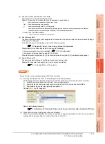
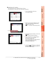
Switching OFF the maintenance time notification output
The maintenance time notification setting which has been set once is not switched OFF even if changing its setting.
Switch OFF the maintenance time notification by the following methods.
• Execute addition time reset.
• Switch OFF each bit of "maintenance time notification cancel information (GS638)".
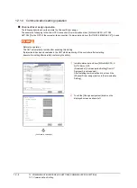
By using system alarm, the message that notifies that the maintenance time is near or it is already maintenance
time is displayed.
For the display of the system alarm, refer to the following.
For the display of the system alarm, refer to the following.
GT Designer3 Version1 Screen Design Manual (Fundamentals)
Item
Description
Setting range
Unit
Maintenance
points
Reference
Backlight maintenance
time notification period.
(0 to 100000 hour)
Sets energization time for the maintenance notification
output.
When 0, no message notification.
The time is counted only when backlight is lit, in every ten
minutes.
0 to 100
<At factory
shipment: 0>
1000
hours
Display section
maintenance time
notification period
(0 to 100000 hour)
Sets energization time for the maintenance notification
output.
When 0, no message notification.
The time is counted only when energized, in every ten
minutes.
0 to 100
<At factory
shipment: 0>
1000
hours
-
Touch key maintenance
time notification count
(0 to 2000000times)
Sets touch key touching count for the maintenance
notification output.
When 0, no message notification.
Counts by every screen touch.
0 to 200
<At factory
shipment: 0>
10000
times
-
Built-in flash memory
maintenance time
notification count
(0 to 200000times)
Sets built-in flash memory writing count for the maintenance
notification output.
When 0, no message notification.
Counts by every writing in built-in flash memory.
0 to 200
<At factory
shipment: 0>
1000
times
-
Summary of Contents for GT16
Page 1: ......
Page 2: ......
Page 46: ...1 4 1 OVERVIEW 1 1 Features ...
Page 54: ...2 8 2 SYSTEM CONFIGURATION 2 2 System Equipment ...
Page 60: ...3 6 3 SPECIFICATIONS 3 4 Battery specifications ...
Page 72: ...5 8 5 UL cUL STANDARDS AND EMC DIRECTIVE 5 2 EMC Directive ...
Page 102: ...6 30 6 OPTION 6 7 Connector Conversion Box ...
Page 106: ...7 4 7 INSTALLATION 7 1 Installing Procedure ...
Page 110: ...8 4 8 COMMUNICATION CABLE 8 1 Overview of Communication Cable ...
Page 130: ...9 20 9 HANDLING OF POWER WIRING AND SWITCH 9 4 Switch Wiring ...
Page 142: ...10 12 10 UTILITY FUNCTION 10 3 Utility Display ...
Page 184: ...11 42 11 DISPLAY AND OPERATION SETTINGS GOT SET UP 11 4 Maintenance Function ...
Page 202: ...12 18 12 COMMUNICATION INTERFACE SETTING COMMUNICATION SETTING 12 3 Ethernet Setting ...
Page 226: ...13 24 13 DEBUG 13 3 Memory Data Control ...
Page 248: ...14 22 14 SELF CHECK 14 2 Batch Self Check ...
Page 350: ...15 102 15 DATA CONTROL 15 3 OS Project Information ...
Page 410: ...19 22 19 TROUBLESHOOTING 19 2 Error Message and System Alarm ...
Page 418: ...App 8 APPENDICES Appendix 3 Transportation Precautions ...
Page 422: ...REVISIONS 4 ...
Page 425: ......
Page 426: ......
Page 427: ......
Page 428: ......
Page 470: ......
Page 510: ...21 22 21 COMPUTER LINK CONNECTION 21 6 Precautions ...
Page 568: ...22 58 22 ETHERNET CONNECTION 22 5 Precautions ...
Page 584: ......
Page 626: ...25 14 25 SERVO AMPLIFIER CONNECTION 25 7 Precautions ...
Page 632: ...26 6 26 ROBOT CONTROLLER CONNECTION 26 6 Precautions ...
Page 647: ...MULTIPLE GOT CONNECTIONS 29 GOT MULTI DROP CONNECTION 29 1 ...
Page 648: ......
Page 659: ...MULTI CHANNEL FUNCTION 30 MULTI CHANNEL FUNCTION 30 1 ...
Page 660: ......
Page 675: ...FA TRANSPARENT FUNCTION 31 FA TRANSPARENT FUNCTION 31 1 ...
Page 676: ......
Page 742: ...31 66 31 FA TRANSPARENT FUNCTION 31 7 Precautions ...
Page 744: ......
Page 766: ...32 22 32 CONNECTION TO IAI ROBOT CONTROLLER 32 7 Precautions ...
Page 802: ...34 10 34 CONNECTION TO OMRON TEMPERATURE CONTROLLER 34 7 Precautions ...
Page 834: ...36 18 36 CONNECTION TO KOYO EI PLC 36 6 Device Range that Can Be Set ...
Page 858: ...38 12 38 CONNECTION TO SHARP PLC 38 6 Device Range that Can Be Set ...
Page 868: ...39 10 39 CONNECTION TO SHINKO TECHNOS INDICATING CONTROLLER 39 7 Precautions ...
Page 902: ...42 6 42 CONNECTION TO TOSHIBA MACHINE PLC 42 6 Device Range that Can Be Set ...
Page 908: ...43 6 43 CONNECTION TO PANASONIC SERVO AMPLIFIER 43 7 Precautions ...
Page 970: ...48 12 48 CONNECTION TO FUJI TEMPERATURE CONTROLLER 48 7 Precautions ...
Page 1052: ...52 26 52 CONNECTION TO AZBIL CONTROL EQUIPMENT 52 7 Precautions ...
Page 1102: ...55 14 55 CONNECTION TO GE PLC 55 7 Precautions ...
Page 1114: ...57 4 57 CONNECTION TO SICK SAFETY CONTROLLER 57 5 Device Range that Can Be Set ...
Page 1128: ...59 2 59 CONNECTION TO HIRATA CORPORATION HNC CONTROLLER ...
Page 1130: ...60 2 60 CONNECTION TO MURATEC CONTROLLER ...
Page 1132: ......
Page 1270: ...62 68 62 MICROCOMPUTER CONNECTION ETHERNET 62 8 Precautions ...
Page 1271: ...MODBUS CONNECTIONS 63 MODBUS R RTU CONNECTION 63 1 64 MODBUS R TCP CONNECTION 64 1 ...
Page 1272: ......
Page 1292: ...64 12 64 MODBUS R TCP CONNECTION 64 7 Precautions ...
Page 1293: ...CONNECTIONS TO PERIPHERAL EQUIPMENT 65 VNC R SERVER CONNECTION 65 1 ...
Page 1294: ......
Page 1298: ...65 4 65 VNC R SERVER CONNECTION 65 4 Setting in Personal Computer ...
Page 1302: ...REVISIONS 4 ...
Page 1305: ......
Page 1306: ......