14.2 System Configuration
14 - 19
INVERTER
C
O
NNE
CTION
14
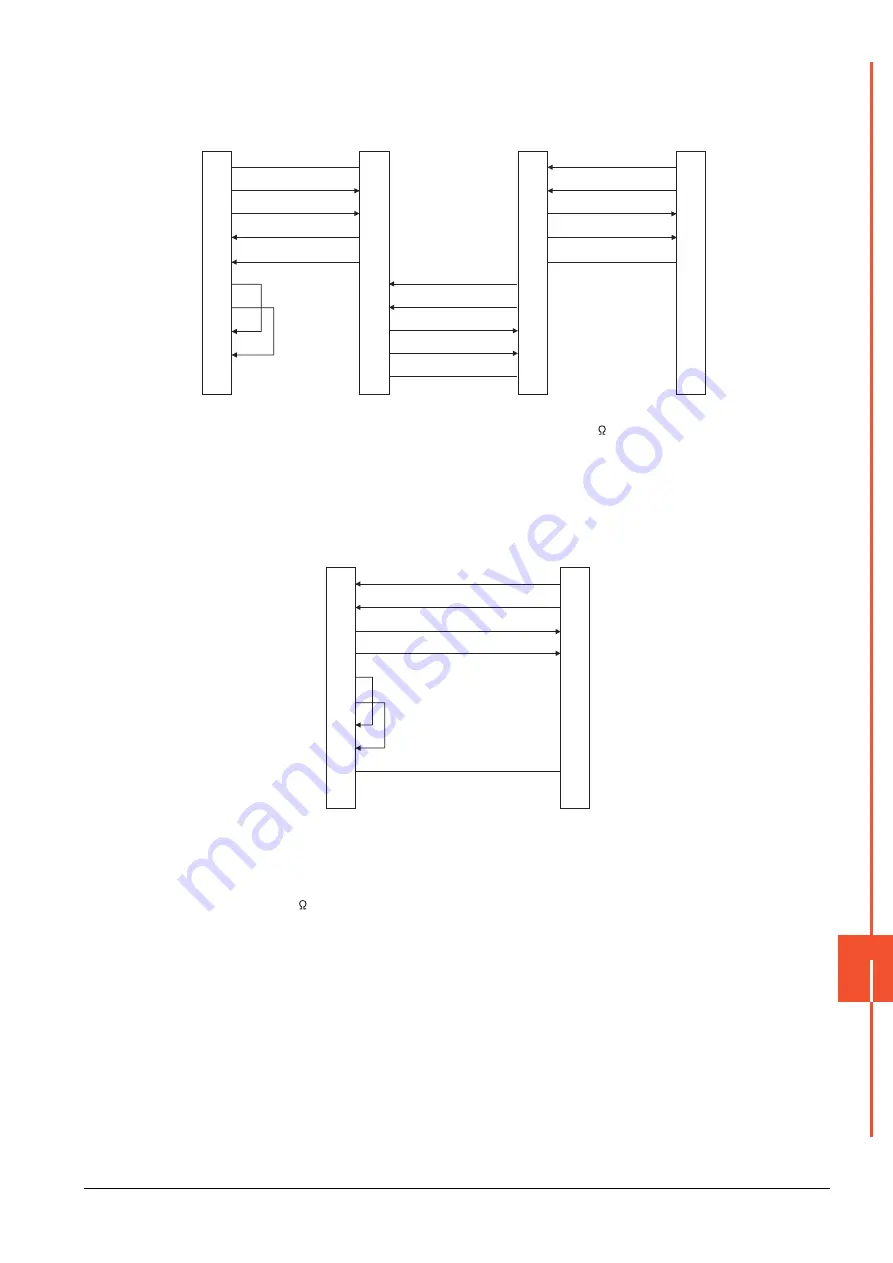
(6) RS-485 connection diagram 6)
*1
Set the terminator switch built in the farthest inverter from the GOT to ON (100 ).
*2
In the case of GT27, GT25(Except GT2505-V), GT23, set the terminating resistor of GOT side, which will be a terminal, to
"Enable".
In the case of GT2505-V, GT21, set the terminating resistor of GOT side, which will be a terminal, to "330
Ω
".
➠
1.4.3 Terminating resistors of GOT
(7) RS-485 connection diagram 7)
*1
In the case of GT27, GT25(Except GT2505-V), GT23, set the terminating resistor of GOT side, which will be a terminal, to
"Disable".
In the case of GT2505-V, GT21, set the terminating resistor of GOT side, which will be a terminal, to "330
Ω
".
➠
1.4.3 Terminating resistors of GOT
*2
Turn ON (100 ) the terminator switch for the FR-E7TR.
SG
SDB
SDA
RDB
RDA
RSA
RSB
CSA
CSB
SDA2
SDB2
RDA2
RDB2
GND
SDA1
SDB1
RDA1
RDB1
GND
GND
RDB1
RDA1
SDB1
SDA1
5
6
1
7
2
3
8
4
9
-
SDA2
SDB2
RDA2
RDB2
GND
SDA2
SDB2
RDA2
RDB2
GND
SDA1
SDB1
RDA1
RDB1
GND
GOT side
*2
Built-in RS-485
terminal block
Station No.0,
or A8ERS
Built-in RS-485
terminal block
Station No.1,
or A8ERS
Built-in RS-485
terminal block
*1
Station No.n,
or A8ERS
GOT side
*1
RDA
RDB
SDA
SDB
RSA
RSB
CSA
CSB
SG
FG
2
7
1
6
3
8
4
9
5
-
SDA
SDB
RDA
RDB
SG
FR-E7TR side
(terminal block)
*2
Summary of Contents for GOT2000 Series
Page 2: ......
Page 84: ......
Page 432: ...6 58 6 6 Precautions ...
Page 578: ...9 54 9 6 Precautions ...
Page 726: ...12 84 12 5 Precautions ...
Page 756: ......
Page 822: ...14 66 14 4 Device Range that Can Be Set ...
Page 918: ...15 96 15 7 Precautions ...
Page 930: ...16 12 16 6 Precautions ...
Page 964: ......
Page 1002: ...19 38 19 7 Precautions ...
Page 1022: ...20 20 20 5 Precautions ...
Page 1023: ...MULTI CHANNEL FUNCTION 21 MULTI CHANNEL FUNCTION 21 1 ...
Page 1024: ......
Page 1054: ...21 30 21 5 Multi channel Function Check Sheet ...
Page 1055: ...FA TRANSPARENT FUNCTION 22 FA TRANSPARENT FUNCTION 22 1 ...
Page 1056: ......
Page 1223: ......


