background image

5 - 68

5.4  PLC Side Setting

(2) When abnormal communication

At abnormal communication, check the followings and execute the Ping command again.
• Mounting condition of Ethernet communication unit
• Cable connecting condition
• Confirmation of switch and network parameter setting
• Operation state of PLC CPU (faulty or not)
• IP address of GOT specified by Ping command

POINT

POINT

POINT

Ethernet diagnostics of GX Developer
Ethernet diagnostics of GX Developer is available to a Ping test from the PLC.
For details of Ethernet diagnostics of GX Developer, refer to the following manual.

User's manual of the Ethernet module

5.4.9

Connecting to C Controller module (Q Series)

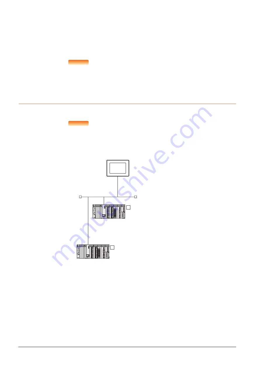
This section describes the settings of the GOT and C Controller module (Q Series) in the following case of the system 
configuration.

POINT

POINT

POINT

C Controller module (Q Series)
For details of C Controller module (Q Series), refer to the following manual.

C Controller Module User's Manual (Hardware Design, Function Explanation)

■1.

System configuration

*1

These setting items do not exist at the PLC side. However, the virtual values must be set on the GOT side.

3. [Controller Setting] and [Ethernet] of GT Designer3

<GOT>
(The settings other than the 
following are set to the default)

Network No.

: 1

PLC No.

: 1

IP address

: 192.168.3.18

Port No.

: 5001

Communication 
format

: UDP(fixed)

Network No.

: 1 (virtual)

PLC No.

: 2 (virtual)

IP address

: 192.168.3.1

Port No.

: 5006(fixed)

Communication 
format

: UDP(fixed) 

<C controller module (Q Series)>
(The settings other than the 
following are set to the default)

1

Network No.

: 1 (virtual)

PLC No.

: 3 (virtual)

IP address

: 192.168.3.2

Port No.

: 5006(fixed) 

Communication 
format

: UDP(fixed)

<C controller module (Q Series)>
(The settings other than the following are 
set to the default)

2

*1
*1

*1

*1

Summary of Contents for GOT2000 Series

Page 1: ...Link CONNECTION INVERTER CONNECTION SERVO AMPLIFIER CONNECTION ROBOT CONTROLLER CONNECTION CNC CONNECTION LASER DISPLACEMENT SENSOR MH11 CONNECTION GOT MULTI DROP CONNECTION MULTIPLE GT21 CONNECTION FUNCTION MULTI CHANNEL FUNCTION FA TRANSPARENT FUNCTION GRAPHIC OPERATION TERMINAL Connection Manual Mitsubishi Electric Products For GT Works3 Version1 GOT2000 Series ...

Page 2: ......

Page 3: ...ake it accessible when required and always forward it to the end user DESIGN PRECAUTIONS WARNING Some failures of the GOT communication unit or cable may keep the outputs on or off Some failures of a touch panel may cause malfunction of the input objects such as a touch switch An external monitoring circuit should be provided to check for output signals which may lead to a serious accident Not doi...

Page 4: ...more simultaneously on the display section Doing so may cause an accident due to an incorrect output or malfunction GT25 GT23 GT21 Do not touch two points or more simultaneously on the display section Doing so may cause a touch switch near the touched points to operate unexpectedly or may cause an accident due to an incorrect output or malfunction When programs or parameters of the controller such...

Page 5: ...ly affecting the communication of the device with the IP address 192 168 0 18 The operation at the IP address duplication depends on the devices and the system GT21 When multiple GOTs connect to the Ethernet network Do not set the IP address 192 168 3 18 for the GOTs and the controllers in the network When one GOT connects to the Ethernet network Do not set the IP address 192 168 3 18 for the cont...

Page 6: ...ws in the following specified torque range GT27 GT25 except GT25 W When loading the communication unit or option unit other than wireless LAN unit to the GOT fit it to the connection interface of the GOT and tighten the mounting screws in the specified torque range 0 36 N m to 0 48 N m with a Phillips head screwdriver No 2 When loading the wireless LAN unit to the GOT fit it to the side interface ...

Page 7: ...mage or soil the GOT or cause foreign matter to enter the GOT resulting in a failure or malfunction CAUTION When installing the supplied fittings on GT2512F S GT2510F V or GT2508F V tighten screws in the specified torque range 0 8 N m to 1 0 N m Meld studs on the control panel to fasten the fittings The studs must have strength adequate to withstand a tightening torque of 0 9 N m or more Make sure...

Page 8: ...s for terminal processing of a wire and tighten them with the specified torque Not doing so can cause a fire failure or malfunction GT2104 R GT2104 P GT2103 P Connect a stranded wire or a solid wire directly or use a rod terminal with an insulation sleeve Correctly wire the GOT power supply section after confirming the rated voltage and terminal arrangement of the product Not doing so can cause a ...

Page 9: ... the operating procedures During the test operation never change the data of the devices which are used to perform significant operation for the system False output or malfunction can cause an accident WARNING When power is on do not touch the terminals Doing so can cause an electric shock or malfunction Correctly connect the battery connector Do not charge disassemble heat short circuit solder or...

Page 10: ...ropped or given an impact dispose of it without using Before touching the unit always touch grounded metals etc to discharge static electricity from human body etc Not doing so can cause the unit to fail or malfunction Use the battery manufactured by Mitsubishi Electric Corporation Use of other batteries may cause a risk of fire or explosion Dispose of used battery promptly Keep away from children...

Page 11: ... card access LED is off before removing the SD card CAUTION If the data storage is removed from the GOT while being accessed by the GOT the data storage and files may be damaged Before removing the data storage from the GOT check the SD card access LED system signal or others to make sure that the data storage is not accessed Turning off the GOT while it accesses the SD card results in damage to t...

Page 12: ... function If these functions are used to perform remote control of control equipment the field operator may not notice the remote control possibly leading to an accident In addition a communication delay or interruption may occur depending on the network environment and remote control of control equipment cannot be performed normally in some cases Before using the above functions to perform remote...

Page 13: ... and or relevant unit s in the manner they will not be exposed to the impact exceeding the impact resistance described in the general specifications of this manual as they are precision devices Failure to do so may cause the unit to fail Check if the unit operates correctly after transportation When fumigants that contain halogen materials such as fluorine chlorine bromine and iodine are used for ...

Page 14: ...23 1 3 7Installing a unit on another unit Checking the unit installation position 1 24 1 4Connection Cables for the Respective Connection 1 28 1 4 1GOT connector specifications 1 28 1 4 2Coaxial cableconnector connection method 1 30 1 4 3Terminating resistors of GOT 1 32 1 4 4Setting the RS 232 485 signal conversion adaptor 1 36 1 5Verifying GOT Recognizes Connected Equipment 1 37 1 6Checking for ...

Page 15: ... REDUNTANT SYSTEM 4 1MELSEC iQ R Series 4 2 4 1 1Connection to built in Ethernet port CPU 4 3 4 1 2Connection to Ethernet module 4 9 4 1 3Connection to CC Link IE Controller Network 4 15 4 1 4Connection to CC Link IE Field Network 4 19 4 1 5Connection to Remote I O Station in CC Link IE Field Network 4 23 4 1 6Connection to CC Link intelligent device station 4 44 4 1 7When connecting via the seria...

Page 16: ... L Series built in Ethernet port CPU one to one connection 5 52 5 4 7Connecting to MELSEC Q L Series built in Ethernet port CPU multiple connection 5 57 5 4 8Connecting to Ethernet module Q L Series 5 63 5 4 9Connecting to C Controller module Q Series 5 68 5 4 10Connecting to Ethernet module QnA Series 5 73 5 4 11Connecting to Ethernet module A Series 5 78 5 4 12Connecting to Ethernet module FX Se...

Page 17: ...ication detail settings 7 28 7 5PLC Side Setting 7 34 7 5 1Connecting serial communication module MELSEC iQ R Series 7 35 7 5 2Connecting serial communication module Q L Series 7 36 7 5 3Connecting serial communication module QnA Series 7 38 7 5 4Connecting computer link module 7 41 7 6Precautions 7 46 8 BUS CONNECTION 8 1Connectable Model List 8 2 8 2System Configuration 8 8 8 2 1Connecting to QC...

Page 18: ... bus system 9 12 9 3GOT Side Settings 9 14 9 3 1Setting communication interface Controller Setting 9 14 9 3 2Communication detail settings 9 15 9 3 3Routing parameter setting 9 17 9 4PLC side setting when connecting to MELSECNET H 9 18 9 4 1System configuration 9 18 9 4 2Switch setting of MELSECNET H network module 9 19 9 4 3Parameter setting 9 20 9 4 4 Controller Setting of GT Designer3 9 26 9 5P...

Page 19: ...ng with CC Link Ver 1 Ver 2 compatibles mixed 12 11 12 3GOT Side Settings 12 12 12 3 1Setting communication interface Controller Setting 12 12 12 3 2Communication detail settings 12 13 12 4PLC Side Setting 12 16 12 4 1Connecting to CC Link module MELSEC iQ R Series with Ver 1 compatible 12 17 12 4 2Connecting to CC Link module MELSEC iQ R Series with Ver 2 compatible 12 20 12 4 3Connecting to CC L...

Page 20: ...INVERTER CONNECTION 14 1Connectable Model List 14 2 14 2System Configuration 14 3 14 2 1Connecting to FREQROL A500 A500L F500 F500L V500 V500L 14 3 14 2 2Connecting to FREQROL E500 S500 S500E F500J D700 F700PJ 14 6 14 2 3Connecting to FREQROL E700 sensorless servo FREQROL E700EX 14 8 14 2 4Connecting to FREQROL A700 F700 700P A800 F800 A800 Plus 14 11 14 2 5Connecting to MD CX522 K A0 14 15 14 2 6...

Page 21: ...LER CONNECTION 16 1Connectable Model List 16 2 16 2System Configuration 16 2 16 2 1Connecting to robot controller CR800 D CRnD 700 16 2 16 3GOT Side Settings 16 3 16 3 1Setting communication interface Controller Setting 16 3 16 3 2Communication detail settings 16 4 16 3 3GOT Ethernet Setting 16 4 16 3 4Ethernet setting 16 5 16 4Robot controller Side Settings 16 6 16 4 1Connecting to robot controll...

Page 22: ...nication detail settings 18 5 18 5Laser Displacement Sensor MH11 Side Settings 18 6 18 5 1Connecting to the Laser Displacement Sensor MH11 18 6 18 6Device Range that Can Be Set 18 6 MULTIPLE GOT CONNECTIONS 19 GOT MULTI DROP CONNECTION 19 1CPU that can be Monitored 19 2 19 2Connectable Model List 19 3 19 3System Configuration 19 21 19 4Connection Diagram 19 22 19 4 1RS 485 cable 19 22 19 5GOT Side...

Page 23: ...ed before starting drawing 21 24 21 4Precautions 21 26 21 4 1Precautions for use 21 26 21 5Multi channel Function Check Sheet 21 27 FA TRANSPARENT FUNCTION 22 FA TRANSPARENT FUNCTION 22 1FA Transparent Function 22 2 22 2Compatible Software 22 3 22 3List of Models that Can Be Monitored 22 14 22 4System Configuration 22 38 22 4 1GX Works3 CW Configurator GX Works2 GX Developer GX LogViewer MX Compon...

Page 24: ...ng PLC by FX Configurator FP 22 127 22 7 13Accessing by FX3U ENET L Configuration tool 22 128 22 7 14Accessing by RT ToolBox3 22 129 22 7 15Accessing by RT ToolBox2 22 139 22 7 16Accessing by NC Configurator2 22 143 22 7 17Accessing by MELSOFT Navigator 22 144 22 7 18Accessing by CPU Module Logging Configuration Tool 22 145 22 7 19Accessing by Setting Monitoring tool for C Controller module 22 146...

Page 25: ... 1D7ML9 PDF e Manual GT Converter2 Version3 Operating Manual for GT Works3 SH 080862ENG 1D7MB2 PDF GOT2000 Series MES Interface Function Manual for GT Works3 Version1 SH 081228ENG PDF Manual name Manual number Model code Format GOT2000 Series Connection Manual Mitsubishi Electric Products For GT Works3 Version1 SH 081197ENG 1D7MJ8 PDF GOT2000 Series Connection Manual Non Mitsubishi Electric Produc...

Page 26: ... GT25 models GT25 W GT2510 WX GT2510 WXTBD GT2510 WXTSD GT2507 W GT2507 WTBD GT2507 WTSD GT25 S GT2512 S GT2512 STBA GT2512 STBD GT2512F S GT2512F STNA GT2512F STND GT25 V GT2510 V GT2510 VTBA GT2510 VTWA GT2510 VTBD GT2510 VTWD GT2510F V GT2510F VTNA GT2510F VTND GT2508 V GT2508 VTBA GT2508 VTWA GT2508 VTBD GT2508 VTWD GT2508F V GT2508F VTNA GT2508F VTND GT2505 V GT2505 VTBD GT25HS V GT2506HS V G...

Page 27: ...t GT15 J71GF13 T2 CC Link communication unit GT15 J61BT13 Wireless LAN communication unit GT25 WLAN Serial multi drop connection unit GT01 RS4 M Connection conversion adapter GT10 9PT5S Field network adapter unit GT25 FNADP Ethernet communication unit GT25 J71E71 100 RS 232 485 signal conversion adapter GT14 RS2T4 9P Abbreviations and generic terms Description Printer unit GT15 PRN Video RGB unit ...

Page 28: ... Attachment GT15 70ATT 98 GT15 70ATT 87 GT15 60ATT 97 GT15 60ATT 96 GT15 60ATT 87 GT15 60ATT 77 GT21 04RATT 40 Panel mounted USB port extension GT14 C10EXUSB 4S GT10 C10EXUSB 5S Connector conversion box GT16H CNB 42S Emergency stop switch guard cover GT16H 60ESCOV Abbreviations and generic terms Description GT Works3 SW1DND GTWK3 J SW1DND GTWK3 E SW1DND GTWK3 C GT Designer3 Version1 Screen design ...

Page 29: ...5C FBDQ E type FBD software package for process control indicates a version MT Works2 Motion controller engineering environment MELSOFT MT Works2 SW DND MTW2 E indicates a version MT Developer SW RNC GSV type integrated start up support software for motion controller Q series indicates a version CW Configurator C Controller module configuration and monitor tool SW1DND RCCPU E indicates a version M...

Page 30: ...HIRATA Hirata Corporation FUJI FUJI ELECTRIC CO LTD YASKAWA YASKAWA Electric Corporation YOKOGAWA Yokogawa Electric Corporation RKC RKC INSTRUMENT INC ALLEN BRADLEY Allen Bradley products manufactured by Rockwell Automation Inc CLPA CC Link Partner Association GE GE Intelligent Platforms Inc HMS HMS Industrial Networks LS IS LS Industrial Systems Co Ltd MITSUBISHI INDIA Mitsubishi Electric India P...

Page 31: ...etting the Communication Interface 1 3 1 2 Writing the Package Data onto the GOT 1 20 1 3 Option Devices for the Respective Connection 1 22 1 4 Connection Cables for the Respective Connection 1 28 1 5 Verifying GOT Recognizes Connected Equipment 1 37 1 6 Checking for Normal Monitoring 1 39 ...

Page 32: ...pplication are properly written onto the GOT 1 2 2Checking the package data writing on GOT Step 4 Attaching the communication unit and connecting the cable Mount the optional equipment and prepare connect the connection cable according to the connection type 1 3Option Devices for the Respective Connection 1 4Connection Cables for the Respective Connection Each chapter System Configuration Each cha...

Page 33: ...which are reflected to GT Designer3 from MELSOFT Navigator changes to green Set items which are displayed in green cells from the MELSOFT Navigator When changing in GT Designer3 refer to the following 3 2 When setting the communication interface for the connection with the iQ Works untargeted equipment set Set by GT Designer3 to the channel connected at Configuration detailed information input in ...

Page 34: ...from the menu Step 2 The Controller Setting dialog box appears Select the channel No to be used from the list menu Step 3 Refer to the following explanations for the setting POINT POINT POINT Channel No 2 to No 4 Use the channel No 2 to No 4 when using the Multi channel function For details of the Multi channel function refer to the following Mitsubishi Electric Products 19 MULTI CHANNEL FUNCTION ...

Page 35: ...ion interface section in each chapter Item Description Use CH Select this item when setting the channel No 2 to No 4 Manufacturer Select the manufacturer of the equipment to be connected to the GOT Type Select the type of the equipment to be connected to the GOT For the settings refer to the following 2 Setting Controller Type I F Select the interface of the GOT to which the equipment is connected...

Page 36: ...U R120CPU R16MTCPU R32MTCPU R64MTCPU R08PCPU R16PCPU R32PCPU R120PCPU R04ENCPU R08ENCPU R16ENCPU R32ENCPU R120ENCPU R08SFCPU R16SFCPU R32SFCPU R120SFCPU R12CCPU V CNC C80 R16NCCPU S1 CR800 R R16RTCPU CR800 D MELSERVO J4 B 1 MELSERVO JE B 1 MELSERVO JE BF 1 MELSEC iQ F FX5U FX5UC MELSERVO J4 B 1 MELSERVO JE B 1 MELSEC Q QS Q17nD M NC DR CRnD 700 Q00CPU Q01CPU Q02CPU Q02HCPU Q06HCPU Q12HCPU Q25HCPU ...

Page 37: ...UDEHCPU Q20UDEHCPU Q26UDEHCPU Q50UDEHCPU Q100UDEHCPU Q03UDVCPU Q04UDVCPU Q06UDVCPU Q13UDVCPU Q26UDVCPU Q04UDPVCPU Q06UDPVCPU Q13UDPVCPU Q26UDPVCPU Q12DCCPU V Q24DHCCPU V VG Q24DHCCPU LS Q26DHCCPU LS Q172DCPU Q173DCPU Q172DCPU S1 Q173DCPU S1 Q172DSCPU Q173DSCPU Q170MCPU Q170MSCPU Q170MSCPU S1 MR MQ100 CNC C70 Q173NCCPU CRnQ 700 Q172DRCPU CR750 Q Q172DRCPU CR751 Q Q172DRCPU CRnD 700 CR750 D CR751 D ...

Page 38: ... Q25PRHCPU QS001CPU MELSERVO J4 B 1 MELSERVO JE B 1 MELSEC QnA MELDAS C6 Q2ACPU Q2ACPU S1 Q3ACPU Q4ACPU Q4ARCPU Q2ASCPU Q2ASCPU S1 Q2ASHCPU Q2ASHCPU S1 MELDAS C6 FCA C6 MELDAS C64 FCA C64 MELSEC L L02CPU L06CPU L26CPU L26CPU BT L02CPU P L06CPU P L26CPU P L26CPU PBT L02SCPU L02SCPU P NZ2GF ETB MELSERVO J4 B 2 MELSERVO JE B 2 MELSERVO JE BF 3 Type Model name ...

Page 39: ...UCPU A2ACPU A2ACPUP21 A2ACPUR21 A2ACPU S1 A2ACPUP21 S1 A2ACPUR21 S1 A3ACPU A3ACPUP21 A3ACPUR21 A1NCPU A1NCPUP21 A1NCPUR21 A2NCPU A2NCPUP21 A2NCPUR21 A2NCPU S1 A2NCPUP21 S1 A2NCPUR21 S1 A3NCPU A3NCPUP21 A3NCPUR21 A2USCPU A2USCPU S1 A2USHCPU S1 A1SCPU A1SCPUC24 R2 A1SHCPU A2SCPU A2SHCPU A1SJCPU A1SJCPU S3 Type Model name ...

Page 40: ...1FXCPU A273UCPU A273UHCPU A273UHCPU S3 A373UCPU A373UCPU S3 A171SCPU A171SCPU S3 A171SCPU S3N A171SHCPU A171SHCPUN A172SHCPU A172SHCPUN A173UHCPU A173UHCPU S1 MELSEC FX FX0 FX0S FX0N FX1 FX2 FX2C FX1S FX1N FX2N FX1NC FX2NC FX3S FX3G FX3GC FX3GE FX3U FX3UC MELSEC WS WS0 CPU0 WS0 CPU1 WS0 CPU3 MELSERVO J2M P8A MELSERVO J2M P8A MELSERVO J2M DU MELSERVO J2M DU Type Model name ...

Page 41: ... J2S CL MELSERVO J2S CL MELSERVO J3 A MELSERVO J3 A MELSERVO J3 T MELSERVO J3 T MELSERVO J4 A MELSERVO J4 A MELSERVO JE A MELSERVO JE A MELSERVO J4 A RJ MELSERVO J4 A RJ MELSERVO JE A MELSERVO JE A FREQROL 500 700 800 Series SENSORLESS SERVO FREQROL S500 FREQROL S500E FREQROL E500 FREQROL F500 FREQROL F500L FREQROL F500J FREQROL A500 FREQROL A500L FREQROL V500 FREQROL V500L FREQROL D700 FREQROL E7...

Page 42: ...position of communication unit to be mounted onto the GOT 3rd stage 2nd stage 1st stage Example In the case of the GT27 Extension interface Standard interface 1 RS 232 interface built in the GOT Standard interface 2 USB interface built in the GOT Standard interface 3 RS 422 485 interface built in the GOT Standard interface 4 Ethernet interface built in the GOT ...

Page 43: ...GOT Ethernet Common Setting Set the following setting which is common to the standard port and the extension port or port 1 and port 2 Default Gateway Peripheral S W Communication Port No Transparent Port No 3 IP Filter Setting By configuring the IP filter setting the access from the specific IP address can be permitted or shut off 1 GOT IP Address Setting Set the GOT IP address 1 Standard Port or...

Page 44: ...Ethernet extended port settings are applied on GOT Enable Ethernet extended port Enable the ethernet extended port GOT IP Address Set the IP address of the GOT IP Address Default 192 168 5 22 0 0 0 0 to 255 255 255 255 Subnet Mask Set the subnet mask for the sub network Only for connection via router If the sub network is not used the default value is set Default 255 255 255 0 0 0 0 0 to 255 255 2...

Page 45: ...uter If the sub network is not used the default value is set Default 255 255 255 0 0 0 0 0 to 255 255 255 255 Select from GOT Setting List Select the GOT set in GOT Setting List dialog GT Designer3 GOT2000 Screen Design Manual Specifying the port number for the wireless LAN Enable the port number setting for the wireless LAN separately from GOT Ethernet common setting Peripheral S W Communication ...

Page 46: ... menu Step 2 For the detailed settings refer to the following manual GT Designer3 GOT2000 Screen Design Manual Item Description Range Default Gateway Set the router address of the default gateway where the GOT is connected Only for connection via router Default 0 0 0 0 0 0 0 0 to 255 255 255 255 Peripheral S W Communication Port No Set the GOT port No for the communication with the peripheral S W ...

Page 47: ...ct Common I F Communication Setting from the menu Step 2 The I F Communication Setting dialog box appears Make the settings with reference to the following explanation POINT POINT POINT When using the parameter reflection function of MELSOFT Navigator When setting Controller Setting in GT Designer3 using the parameter function of MELSOFT Navigator all of I F Communication Setting are grayout and c...

Page 48: ... to be connected to the GOT I F 1 I F 2 I F 3 The communication type of the GOT standard interface is displayed RS232 Setting To validate the 5V power supply function in RS232 mark the Enable the 5V power supply checkbox The RS232 setting is invalid when the CH No of I F 1 RS232 is 9 GT21 is not supported Ethernet connection setting Set the channel number and the communication driver to the Ethern...

Page 49: ...ase set the device again 2 When the changed Manufacturer or Controller Type does not correspond to the network The network will be set to the host station 3 When the Manufacturer or Controller Type is changed to None The GT Designer3 displays the device of the changed channel No as In this case set the device again Since the channel No is retained the objects can be reused in other channel No in a...

Page 50: ... Select Package Data for Write Data The capacity of the transfer data is displayed in Data Size Check that the destination drive has the sufficient available space Step 2 Select Destination Drive Step 3 When the system application or the special data is required to be added to the package data or deleted click the Write Option button and configure the setting in the Write Option dialog Step 4 Clic...

Page 51: ...Package Data for Read Data Select the drive where the project data or the package data is stored for Source Drive Step 2 Set PC Side Set the reading destination of the project for Destination To read the project data to GT Designer3 select GT Designer3 When Read Data is Package Data the project data cannot be read to GT Designer3 To read the project data as a file click the button to set the savin...

Page 52: ... Bus connection 1ch unit standard model GT15 QBUS2 For QCPU Q mode motion controller CPU Q series Bus connection 2ch unit standard model GT15 ABUS For A QnACPU motion controller CPU A series Bus connection 1ch unit standard model GT15 ABUS2 For A QnACPU motion controller CPU A series Bus connection 2ch unit standard model GT15 75QBUSL For QCPU Q mode motion controller CPU Q series Bus connection 1...

Page 53: ...Common Input Sink Type Output Product name Model Specifications RS 485 terminal block conversion modules FA LTBGT2R4CBL05 RS 422 485 Connector RS 485 Terminal block Supplied connection cable dedicated for the conversion unit FA LTBGT2R4CBL10 FA LTBGT2R4CBL20 Product name Model Specifications Serial multi drop connection unit GT01 RS4 M GOT multi drop connection module Mitsubishi Electric Products1...

Page 54: ...nection unit to be used 1 Wide bus units GT15 75QBUS 2 L GT15 75ABUS 2 L GT15 QBUS2 GT15 ABUS2 Install a bus connection unit in the 1st stage of the extension interface If a bus connection unit is installed in the 2nd stage or above the unit cannot be used Example Installing a bus connection unit and serial communication units 2 Standard size bus connection unit GT15 QBUS and GT15 ABUS A bus conne...

Page 55: ...twork communication unit or CC Link communication unit in the 1st stage of an extension interface If a bus connection unit is installed in the 2nd stage or above the unit cannot be used Example When installing a MELSECNET H communication unit and a serial communication unit 3 When using a serial communication unit A serial communication unit can be installed in any position 1st to 3rd stage of the...

Page 56: ...ommunication unit Example Installing a field network adapter unit 5 When using the sound output unit or external I O unit The sound output unit or external I O unit can be installed in any position 1st to 3rd stage of the extension interface Example When installing a sound output unit Communication unit Field network adapter unit Communication unit Communication unit Field network adapter unit Fie...

Page 57: ...age of the extension interface These communication units cannot be used if installed in the 2nd or higher stage When any of these units is used the communication units indicated below must be installed in the 2nd stage of the extension interface Example When installing a video input unit and a MELSECNET H communication unit Communication unit Model Bus connection unit GT15 QBUS2 GT15 ABUS2 MELSECN...

Page 58: ...ector and connector cover applicable to the GOT connector 1 Connector specifications 1 The terminal block MC1 5 9 ST 3 5 or corresponding product of the cable side is packed together with the GT2104 RTBD GT2103 PMBDS2 2 Connector pin arrangement GOT Hardware Version 1 Connector type Connector model Manufacturer GT27 GT25 GT23 GT2107 W GT2105 QTBDS GT2105 QMBDS 9 pin D sub male inch screw fixed typ...

Page 59: ... Connector model Manufacturer GT27 GT25 GT23 GT2107 W GT2105 QTBDS GT2105 QMBDS 9 pin D Sub female M2 6 millimeter screw fixed type 17LE 13090 27 D2AC DDK Ltd GT2104 PMBD GT2103 PMBD 5 pin terminal block 1 MC1 5 5 G 3 5BK PHOENIX CONTACT Inc GT2104 RTBD GT2104 PMBDS GT2103 PMBDS GT2103 PMBLS 9 pin terminal block 2 MC1 5 9 G 3 5BK PHOENIX CONTACT Inc GT15 RS4 9S 9 pin D Sub female M2 6 millimeter s...

Page 60: ...with the dimensions as shown below Note that the external conductor should be cut to the same dimension as the tapered section of the clamp and smoothed down to the clamp Step 4 Solder the contact to the internal conductor Cable in use B C 3C 2V 6 mm 3 mm 5C 2V 5C 2V CCY 7 mm 5 mm CAUTION Solder the coaxial cable connectors properly Insufficient soldering may result in malfunctions Nut Washer Gask...

Page 61: ...ut into the plug shell Precautions for soldering Note the following precautions when soldering the internal conductor and contact Make sure that the solder does not bead up at the soldered section Make sure there are no gaps between the connector and cable insulator or they do not cut into each other Perform soldering quickly so the insulation material does not become deformed ...

Page 62: ...esistor in each connection type refer to the following 1 RS 422 485 communication unit Set the terminating resistor using the terminating resistor setting switch 1 The default setting is Disable For RS422 485 communication unit Terminating resistor 1 Switch No 1 2 100 OHM ON ON Disable OFF OFF SW1 O N 1 2 ON SW1 ON 1 2 Rear view of RS 422 485 communication unit Terminating resistor setting switch ...

Page 63: ...EDURES FOR MONITORING 2 GT27 Set the terminating resistor using the terminating resistor setting switch 1 The default setting is Disable For GT2710 V Terminating resistor 1 Switch No 1 2 100 OHM ON ON Disable OFF OFF ON 1 2 Terminating resistor setting switch inside the cover ...

Page 64: ...rminating resistor setting switch 1 The default setting is Disable For GT2510 V 4 GT2505 V Set the terminating resistor using the terminating resistor selector Terminating resistor 1 Switch No 1 2 100 OHM ON ON Disable OFF OFF ON 1 2 Terminating resistor setting switch inside the cover Terminating resistor selector switch ...

Page 65: ...e terminating resistor setting switch 1 The default setting is Disable For GT2310 V 6 GT21 Set the terminating resistor using the terminating resistor selector For GT2103 PMBD Terminating resistor 1 Switch No 1 2 100 OHM ON ON Disable OFF OFF ON 1 2 Terminating resistor setting switch inside the cover USB Terminating resistor selector switch ...

Page 66: ...ng the utility function of the GOT main unit refer to the following manual GOT2000 Series User s Manual Utility 1 Setting the 2 wire 4 wire terminating resistor setting switch POINT POINT POINT RS 232 485 signal conversion adapter For details on the RS 232 485 signal conversion adapter refer to the following manual GT14 RS2T4 9P RS 232 485 Signal Conversion Adapter User s Manual Setting item Set v...

Page 67: ...on unit installation status For details on the Utility refer to the following manual GOT2000 Series User s Manual Utility Step 1 After powering up the GOT touch GOT basic set Controller from the Utility Step 2 The Communication Settings appears Step 3 Verify that the communication driver name to be used is displayed in the communication interface box to be used Step 4 When the communication driver...

Page 68: ... the following GOT2000 Series User s Manual Utility 3 Communication interface setting by the Utility The communication interface setting can be changed on the Utility s Communication setting after writing Controller Setting of project data For details on the Utility refer to the following manual GOT2000 Series User s Manual Utility 4 Precedence in communication settings When settings are made by G...

Page 69: ...r to the following manual GOT2000 Series User s Manual Utility POINT POINT POINT Alarm popup display With the alarm popup display function alarms are displayed as a popup display regardless of whether an alarm display object is placed on the screen or not regardless of the display screen Since comments can be flown from right to left even a long comment can be displayed all For details of the alar...

Page 70: ...settings and proper cable connection Display the I O check screen by Main Menu Display the I O check screen by Maintenance I O check For details on the I O check refer to the following manual GOT2000 Series User s Manual Utility Step 1 Touch CPU on the I O check screen Touching CPU executes the communication check with the connected PLC Step 2 When the communication screen ends successfully the sc...

Page 71: ...ds successfully it means correct communication interface settings and proper cable connection Display the communication monitoring function screen by Main Menu Comm Setting Comm Monitor For details on the communication monitoring function refer to the following manual GOT2000 Series User s Manual Utility Operation of communication monitoring function screen Comm Setting Main Menu Comm Monitor Touc...

Page 72: ...y the Utility screen of the GOT For details on the operation method of the GOT Utility screen refer to the following manual GOT2000 Series User s Manual Utility 2 For CC Link IE Controller Network system The communication status between the GOT and CC Link IE Controller Network can be confirmed by the utility screen of the GOT For details on the operation method of the GOT Utility screen refer to ...

Page 73: ...ility screen of the GOT For details on the operation method of the GOT Utility screen refer to the following manual GOT2000 Series User s Manual Utility 4 For CC Link system The communication status between the GOT and the CC Link System can be confirmed by the Utility screen of the GOT For details on the operation method of the GOT Utility screen refer to the following manual GOT2000 Series User ...

Page 74: ...168 3 18 Request timed out 2 When using the Test of GT Designer3 Select Communication Communication settings from the menu to display TEST Step 1 Set the PC side I F to the Ethernet Step 2 Specify the GOT IP Address of the Communication Configuration and click the Test button Step 3 Check if GT Designer3 has been connected to the GOT 3 When abnormal communication At abnormal communication check th...

Page 75: ...CEDURES FOR MONITORING 2 Confirming the communication state on the GOT PING Test can be confirmed by the Utility screen of the GOT For details on the operation method of the GOT Utility screen refer to the following manual GOT2000 Series User s Manual Utility ...

Page 76: ...Total No of the faulty connected equipment is stored POINT POINT POINT When monitoring GS230 on Numerical Display When monitoring GS230 on Numerical Display check mask processing with data operation tab as the following For the data operation refer to the following manual GT Designer3 GOT2000 Screen Design Manual Numerical Display Data Operation tab Device b15 to b8 b7 to b0 GS230 00H fixed No of ...

Page 77: ...0 29 28 27 26 25 24 23 22 21 20 19 18 17 GS233 48 47 46 45 44 43 42 41 40 39 38 37 36 35 34 33 GS234 64 63 62 61 60 59 58 57 56 55 54 53 52 51 50 49 GS235 80 79 78 77 76 75 74 73 72 71 70 69 68 67 66 65 GS236 96 95 94 93 92 91 90 89 88 87 86 85 84 83 82 81 GS237 112 111 110 109 108 107 106 105 104 103 102 101 100 99 98 97 GS238 128 127 126 125 124 123 122 121 120 119 118 117 116 115 114 113 Device...

Page 78: ...3 b2 b1 b0 GS281 GS301 GS321 GS341 15 14 13 12 11 10 9 8 7 6 5 4 3 2 1 0 1 GS282 GS302 GS322 GS342 31 30 29 28 27 26 25 24 23 22 21 20 19 18 17 16 GS283 GS303 GS323 GS343 47 46 45 44 43 42 41 40 39 38 37 36 35 34 33 32 GS284 GS304 GS324 GS344 63 62 61 60 59 58 57 56 55 54 53 52 51 50 49 48 GS285 GS305 GS325 GS345 79 78 77 76 75 74 73 72 71 70 69 68 67 66 65 64 GS286 GS306 GS326 GS346 95 94 93 92 9...

Page 79: ...em monitor of GX Developer check if the PLC CPU recognizes the GOT or not For the GX Developer operation method refer to the following manual GX Developer Version Operating Manual 1 Check the Module Name I O Address and Implementation Position The display example is based on GX Developer Version 8 Startup procedure GX Developer Diagnostics System monitor No error displayed at all times Not display...

Page 80: ...procedure GX Developer Diagnostics MELSECNET II 10 H diagnostics 3 Checking if the GOT is performed the data link correctly 1 For MELSECNET H MELSECNET 10 network system Check if the GOT is performed the data link correctly in Other station information For the GX Developer operation method refer to the following manual Q Corresponding MELSECNET H Network System Reference Manual PLC to PLC network ...

Page 81: ...e status display The display example on GX Developer Version 8 Startup procedure GX Developer Diagnostics CC IE Control diagnostics CC IE Control Network Diagnostics 3 For CC Link system Use Monitoring other station of the GX Developer to check if the GOT is correctly performed the data link For the GX Developer operation method refer to the following manual CC Link System Master Local Module User...

Page 82: ...ller Network Perform the line test from the control station of the CC Link IE Controller Network to check the wiring state of the fiber optic cable For the line testing method refer to the following manual CC Link IE Controller Network Reference Manual 2 Checking the wiring state of the CC Link dedicated cable For CC Link system only Check if the CC Link dedicated cable is connected correctly to a...

Page 83: ... 5 1 6 DIRECT CONNECTION TO CPU 6 1 7 SERIAL COMMUNICATION CONNECTION 7 1 8 BUS CONNECTION 8 1 9 MELSECNET H CONNECTION PLC TO PLC NETWORK MELSECNET 10 CONNECTION PLC TO PLC NETWORK 9 1 10 CC Link IE CONTROLLER NETWORK CONNECTION 10 1 11 CC Link IE FIELD NETWORK CONNECTION 11 1 12 CC Link CONNECTION INTELLIGENT DEVICE STATION 12 1 13 CC Link CONNECTION Via G4 13 1 ...

Page 84: ......

Page 85: ... 1 MELSEC iQ R RnMT NC RT CR800 D GT27 GT25 only 2 13 2 2 MELSEC iQ R RnMT RT CR800 D GT21 only 2 33 2 3 MELSEC iQ F 2 39 2 4 MELSEC Q QS Q17nD M NC DR CRnD 700 2 55 2 5 MELSEC QnA MELDAS C6 2 58 2 6 MELSEC L 2 59 2 7 MELSEC A 2 63 2 8 MELSEC FX 2 65 2 9 MELSEC WS 2 67 ...

Page 86: ...the models even though belonging to the same series Please make the setting according to the specifications of the controller actually used When a non existent device or a device number outside the range is set other objects with correct device settings may not be monitored 2 1MELSEC iQ R RnMT NC RT CR800 D GT27 GT25 only 2 2MELSEC iQ R RnMT RT CR800 D GT21 only 2 3MELSEC iQ F 2 4MELSEC Q QS Q17nD...

Page 87: ...function module Set the first 2 digits of the 3 digit head I O number Unit No Set when the buffer memory G is selected Set the head I O number of the buffer memory for the intelligent function module Set the first 2 digits of the 3 digit head I O number MELSEC FX buffer memory Mask type Set for using the buffer memory of MELSEC FX series 2 Set the mask type for monitoring or writing only specified...

Page 88: ...the connected simple motion module Axis No This item can be set only when the Motion controller or Simple motion is selected Set the axis number of the servo amplifier to be monitored Network No n This item can be set only when the following devices are selected The value set in device name n is input Link input link direct JnX Link output link direct JnY Link relay link direct JnB Link special re...

Page 89: ...he cyclic transmission is changed to the transient transmission regardless of the network type resulting in delay of the object display 3 Setting the device by inputting directly from the keyboard When setting the device by inputting directly from the keyboard set the items as follows For devices except buffer memory BM G motion controller simple motion SFC Block No BLS For device BM and CPU No 0 ...

Page 90: ...ck No BLS Device number Head I O number of buffer memory Device name CPU No 1 to 4 Device number Device name Unit No PLC station num NW No Device number Device name Unit No CPU No 1 to 4 PLC station num NW No When selecting motion controller device Device number Device name Axis number Unit No When selecting motion controller device Device number Device name Axis number Device number SFC Block No ...

Page 91: ...2769 or less and 32768 or more Format Signed Decimal Hexadecimal notation Data Type Unsigned BIN16 Unsigned BIN32 for 0x10000 or more Format Hexadecimal Decimal point notation positive values only Data Type Unsigned BIN16 Unsigned BIN32 as necessary Format Real Digits Integral Set the number of digits in the integral portion Digits Fractional Set the number of digits in the fractional portion Adju...

Page 92: ...is 0001H when monitoring BM 4321H as mask type 1 BM0 0001H when writing input value 4321H to BM0 0000H as mask type 1 For 32 bits Monitor and write only b0 to b3 and b16 to 19 of the buffer memory Example The monitor value is 00050001H when monitoring BM0 87654321H as mask type 1 BM0 00050001H when writing input value 87654321H to BM0 00000000H as mask type 1 BM0 Monitor value H 4 3 2 1 0 0 0 1 H ...

Page 93: ...ue 87654321H to BM0 00000000H as mask type 2 d Mask type 3 For 16 bits Monitor and write only b8 to b11 of the buffer memory Example The monitor value is 0003H when monitoring BM0 4321H as mask type 3 BM0 0100H when writing input value 4321H to BM0 0000H as mask type 3 BM0 Monitor value H 4 3 2 1 0 0 0 2 H BM0 Before writing After writing BM0 Input value H 4 3 2 1 0 0 0 0 H 0 0 1 0 H H BM0 8 7 6 5...

Page 94: ... For 32 bits Monitor and write only b12 to b15 and b28 to 31 of the buffer memory Example The monitor value is 00080004H when monitoring BM0 87654321H as mask type 4 BM0 50001000H for writing input value 87654321H to BM0 00000000H as mask type 4 H BM0 8 7 6 5 4 3 2 1 0 0 0 7 0 0 0 3 H Monitor value H BM0 8 7 6 5 4 3 2 1 0 0 0 0 0 0 0 0 H Input value BM0 0 5 0 0 0 1 0 0 H Before writing After writi...

Page 95: ...ue 87654321H to BM0 00000000H as mask type 5 g Mask type 6 For 16 bits Monitor and write only b8 to b15 of the buffer memory Example The monitor value is 0043H when monitoring BM0 4321H as mask type 6 BM0 2100H when writing input value 4321H to BM0 0000H as mask type 6 BM0 Monitor value H 4 3 2 1 0 0 2 1 H BM0 Before writing After writing BM0 Input value H 4 3 2 1 0 0 0 0 H 0 0 2 1 H H BM0 8 7 6 5...

Page 96: ...e when setting the devices b Indirect specification 1 Specify the module No of the special function unit or special function block indirectly to monitor or write when setting the devices by using the 16 bit GOT internal data register GD10 to GD25 When specifying the station No from 100 to 115 on GT Designer3 the value of GD10 to GD25 corresponding to the module No will be the module No of the spec...

Page 97: ...t CT CT0 to CT8993439 Coil CC CC0 to CC8993439 Long counter 1 Contact LCT LCT0 to LCT4761215 Coil LCC LCC0 to LCC4761215 Special relay SM SM0 to SM4095 Retentive timer 1 Contact SS SS0 to SS8993439 Coil SC SC0 to SC8993439 Long retentive timer 1 2 Contact LSS LSS0 to LSS2529407 Coil LSC LSC0 to LSC2529407 Safety internal relay SAM 5 SAM0 to SAM638975 Safety timer 5 Contact SATT SATT0 to SATT35487 ...

Page 98: ...ng range of each word device Word device Data register D 1 D0 to D10117631 Decimal number Special data register SD SD0 to SD4095 Link register W 1 W0 to W9A61FF Hexadecimal number Timer current value TN 1 TN0 to TN8993439 Decimal number Counter current value CN 1 CN0 to CN8993439 Retentive timer current value SN 1 SN0 to SN8993439 Link special register SW 1 SW0 to SW9A61FF Hexadecimal number File ...

Page 99: ...parameter PT 3 8 PT1 to PT80 PT1001 to PT1080 Status display ST 3 5 ST0 to ST48 Extension setting 2 parameter PE 3 8 PE1 to PE64 PE1001 to PE1064 Extension setting 3 parameter PF 3 8 PF1 to PF64 PF1001 to PF1064 Network setting parameter PN 3 8 PN1 to PN32 PN1001 to PN1032 Alarm current alarm extended for J4 ALM 3 5 ALM0 to ALM1 ALM11 to ALM59 Alarm alarm history extended for J4 ALM 3 5 ALM200 to ...

Page 100: ...55 Use the following devices to write data to the EEPROM of a servo amplifier PA PN 1001 to 1032 PB PE PF 1001 to1064 PC PT 1001 to 1080 PD PL 1001 to 1048 POS SPD ACT DCT DWL AUX 1001 to 1255 9 If a bit specified word device is used in the random read processing GT SoftGOT2000 or GT Simulator3 uses the value of the bit device in block No 0 only The bit device status depends on the SFC program sta...

Page 101: ... display data clear SP1 Current alarm clear SP2 Alarm history clear SP3 External input signal prohibited SP4 External output signal prohibited SP5 External input signal resumed SP6 External output signal resumed Device name Item Symbol OM0 Normal mode not test operation mode OM1 JOG operation OM2 Positioning operation OM3 For manufacturer setting OM4 Output signal DO forced output OM5 1 One step s...

Page 102: ...n position range INP PA11 PA1011 Forward rotation torque limit positive direction thrust limit 2 TLP PA12 PA1012 Reverse rotation torque limit negative direction thrust limit 2 TLN PA13 PA1013 For manufacturer setting PA14 PA1014 Rotation direction selection travel direction selection POL PA15 PA1015 Encoder output pulses 3 ENR PA16 PA1016 Encoder output pulses 2 3 ENR2 PA17 PA1017 Servo motor ser...

Page 103: ...ression control 1 Resonance frequency VRF12 PB21 PB1021 Vibration suppression control 1 Vibration frequency dumping VRF13 PB22 PB1022 Vibration suppression control 1 Resonance frequency dumping VRF14 PB23 PB1023 Low pass filter selection VFBF PB24 PB1024 Slight vibration suppression control selection MVS PB25 PB1025 Function selection B 1 BOP1 PB26 PB1026 Gain switching function CDP PB27 PB1027 Ga...

Page 104: ...bration suppression control 2 Resonance frequency VRF22 PB54 PB1054 Vibration suppression control 2 Vibration frequency dumping VRF23 PB55 PB1055 Vibration suppression control 2 Resonance frequency dumping VRF24 PB56 PB1056 Vibration suppression control 2 Vibration frequency after gain switching VRF21B PB57 PB1057 Vibration suppression control 2 Resonance frequency after gain switching VRF22B PB58...

Page 105: ... data High 3 MOSDH PC15 to PC16 PC1015 to PC1016 For manufacturer setting PC17 PC1017 Function selection C 4 COP4 PC18 PC1018 Function selection C 5 COP5 PC19 PC1019 Function selection C 6 2 COP6 PC20 PC1020 Function selection C 7 COP7 PC21 PC1021 Alarm history clear BPS PC22 to PC23 PC1022 to PC1023 For manufacturer setting PC24 PC1024 Forced stop deceleration time constant RSBR PC25 PC1025 For m...

Page 106: ...10 For manufacturer setting PD11 PD1011 Input filter setting Note DIF PD12 PD1012 Function selection D 1 DOP1 PD13 PD1013 Function selection D 2 DOP2 PD14 PD1014 Function selection D 3 DOP3 PD15 PD1015 Driver communication setting 3 IDCS PD16 PD1016 Driver communication setting Master Transmit data selection 1 3 MD1 PD17 PD1017 Driver communication setting Master Transmit data selection 2 3 MD2 PD...

Page 107: ...PT23 to PT26 PT1023 to PT1026 For manufacturer setting PT27 PT1027 Indexer method Operation mode selection ODM PT28 PT1028 Split numbers with one revolution STN PT29 PT1029 Function selection T 3 TOP3 PT30 to PT33 PT1030 to PT1033 For manufacturer setting PT34 PT1034 Point table default PDEF PT35 PT1035 Function selection T 5 TOP5 PT36 to PT38 PT1036 to PT1038 For manufacturer setting PT39 PT1039 ...

Page 108: ...BD PE6 PE1006 Fully closed loop control Speed deviation error detection level 1 BC1 PE7 PE1007 Fully closed loop control Position deviation error detection level 1 BC2 PE8 PE1008 Fully closed loop dual feedback filter 1 DUF PE9 PE1009 For manufacturer setting PE10 PE1010 Fully closed loop function selection 3 1 FCT3 PE11 to PE33 PE1011 to PE1033 For manufacturer setting PE34 PE1034 Fully closed lo...

Page 109: ...ion compen coefficient 2 3 TIC PF21 PF1021 Drive recorder switching time setting DRT PF22 PF1022 For manufacturer setting PF23 PF1023 Vibration tough drive Oscillation detection level OSCL1 PF24 PF1024 Vibration tough drive function selection OSCL2 PF25 PF1025 SEMI F47 function Instantaneous power failure detection time CVAT PF26 to PF30 PF1026 to PF1030 For manufacturer setting PF31 PF1031 Machin...

Page 110: ...ion error detection level LB1 PL6 PL1006 Speed deviation error detection level LB2 PL7 PL1007 Torque thrust deviation error detection level LB3 PL8 PL1008 Linear servo motor DD motor function selection 3 LIT3 PL9 PL1009 Magnetic pole detection voltage level LPWM PL10 to PL16 PL1010 to PL1016 For manufacturer setting PL17 PL1017 Magnetic pole detection Minute position detection method Function sele...

Page 111: ... Load side encoder information 1 ST18 Load side encoder information 2 ST19 Analog monitor output voltage 1 ST20 Analog monitor output voltage 2 ST21 AB phase output pulse F B integrated value ST22 Temperature of servo motor thermistor ST23 Servo motor side cumulative feedback pulses before gear ST24 Electrical angle ST25 to ST29 For manufacturer setting ST30 Motor load side position difference 1 S...

Page 112: ...lative feedback pulses ALM27 Servo status alarm Load side encoder droop pulses 1 ALM28 Servo status alarm Load side encoder information 1 ALM29 Servo status alarm Load side encoder information 2 ALM30 Servo status alarm Analog monitor output voltage 1 ALM31 Servo status alarm Analog monitor output voltage 2 ALM32 Servo status alarm AB phase output pulse F B integrated value ALM33 Servo status alar...

Page 113: ...larm in past ALM209 Alarm number from Alarm History 9th alarm in past ALM210 Alarm number from Alarm History 10th alarm in past ALM211 Alarm number from Alarm History 11th alarm in past ALM212 Alarm number from Alarm History 12th alarm in past ALM213 Alarm number from Alarm History 13th alarm in past ALM214 Alarm number from Alarm History 14th alarm in past ALM215 Alarm number from Alarm History 1...

Page 114: ...arm History 4th alarm in past ALM245 Detailed alarm from Alarm History 5th alarm in past ALM246 Detailed alarm from Alarm History 6th alarm in past ALM247 Detailed alarm from Alarm History 7th alarm in past ALM248 Detailed alarm from Alarm History 8th alarm in past ALM249 Detailed alarm from Alarm History 9th alarm in past ALM250 Detailed alarm from Alarm History 10th alarm in past ALM251 Detailed...

Page 115: ...is data shift judgment test mode MD2 1 Machine diagnosis data status MD3 2 Machine diagnosis data coulomb friction torque in positive direction MD4 2 Machine diagnosis data friction torque at rated speed in positive direction MD5 2 Machine diagnosis data coulomb friction torque in negative direction MD6 2 Machine diagnosis data friction torque at rated speed in negative direction MD7 2 Machine dia...

Page 116: ...evices switched on through communication 1 DI5 Statuses of input devices switched on through communication 2 DI6 Statuses of input devices switched on through communication 3 1 Device name Item Symbol DO0 Output device statuses 1 DO1 Output device statuses 2 DO2 Output device statuses 3 1 DO3 For manufacturer setting DO4 External output pin statuses Device name Item Symbol ALD0 Cumulative energiza...

Page 117: ...CT8993439 Coil CC CC0 to CC8993439 Long counter 1 Contact LCT LCT0 to LCT4761215 Coil LCC LCC0 to LCC4761215 Special relay SM SM0 to SM4095 Retentive timer 1 Contact SS SS0 to SS8993439 Coil SC SC0 to SC8993439 Long retentive timer 1 2 Contact LSS LSS0 to LSS2529407 Coil LSC LSC0 to LSC2529407 Safety internal relay SAM 5 SAM0 to SAM638975 Safety timer 5 Contact SATT SATT0 to SATT35487 Coil SATC SA...

Page 118: ...ink relay JnB JnB0 to JnB7FFF Link special relay JnSB JnSB0 to JnSB1FF Bit specified word device Except the timer counter retentive timer and index register Z Setting range of each word device Word device Data register D 1 D0 to D10117631 Decimal number Special data register SD SD0 to SD4095 Link register W 1 W0 to W9A61FF Hexadecimal number Timer current value TN 1 TN0 to TN8993439 Decimal number...

Page 119: ...1064 Extension setting parameter PC 2 3 8 PC1 to PC80 PC1001 to PC1080 I O setting parameter PD 2 3 8 PD1 to PD48 PD1001 to PD1048 Positioning control parameter PT 2 3 8 PT1 to PT80 PT1001 to PT1080 Linear servo motor DD motor setting parameter PL 2 3 8 PL1 to PL48 PL1001 to PL1048 Status display ST 2 3 5 ST0 to ST48 Extension setting 2 parameter PE 2 3 8 PE1 to PE64 PE1001 to PE1064 Extension set...

Page 120: ...se the following devices to write data to the EEPROM of a servo amplifier PA PN 1001 to 1032 PB PE PF 1001 to1064 PC PT 1001 to 1080 PD PL 1001 to 1048 POS SPD ACT DCT DWL AUX 1001 to 1255 9 If a bit specified word device is used in the random read processing GT SoftGOT2000 or GT Simulator3 uses the value of the bit device in block No 0 only Word device One touch tuning data OTS 2 3 5 OTS0 to OTS3...

Page 121: ...SET The bit device status depends on the SFC program status active or inactive When the SFC program is inactive the bit device is off stores 0 If a step relay S is used in the random read processing specify the relevant step relay block BLS on GT SoftGOT2000 or GT Simulator3 ...

Page 122: ...t switch cannot be used Use Momentary Set and Reset for bit switch actions 2 Word device and double word device Only writing is possible Numerical input cannot be used Use a word switch for writing The following shows correspondences between virtual devices for servo amplifier and data of the servo amplifier used with the GOT 2 1 MELSEC iQ R RnMT NC RT CR800 D GT27 GT25 only ...

Page 123: ...0 to TC1023 Counter Contact CT CT0 to CT1023 Coil CC CC0 to CC1023 Long counter Contact LCT LCT0 to LCT1023 Coil LCC LCC0 to LCC1023 Special relay SM SM0 to SM9999 Retentive timer Contact SS SS0 to SS1023 Coil SC SC0 to SC1023 Servo amplifier request SP 5 9 SP0 to SP6 Operation mode selection OM 5 9 OM0 to OM2 OM4 to OM5 Instruction demand for test operation TMB 5 9 TMB1 to TMB6 One touch tuning O...

Page 124: ...er PB 6 7 9 PB1 to PB64 PB1001 to PB1064 Extension setting parameter PC 6 7 9 PC1 to PC64 PC1001 to PC1064 I O setting parameter PD 6 7 9 PD1 to PD48 PD1001 to PD1048 Linear servo motor DD motor setting parameter PL 6 7 9 PL1 to PL48 PL1001 to PL1048 Status display ST 4 7 9 ST0 to ST48 Extension setting 2 parameter PE 6 7 9 PE1 to PE64 PE1001 to PE1064 Extension setting 3 parameter PF 6 7 9 PF1 to...

Page 125: ...efore the writing In addition the monitoring performance may slow down Therefore select one of the following items for the data type of the device Signed BIN16 Unsigned BIN16 Signed BIN32 Unsigned BIN 32 When you use the value of the servo amplifier device remember that only the integer portion of the value is stored in the device To display a real number on the numerical display or numerical inpu...

Page 126: ...larm history clear SP3 External input signal prohibited SP4 External output signal prohibited SP5 External input signal resumed SP6 External output signal resumed Device name Item Symbol OM0 Normal mode not test operation mode OM1 JOG operation OM2 Positioning operation OM3 For manufacturer setting OM4 Output signal DO forced output OM5 For manufacturer setting Device name Item Symbol TMB1 Tempora...

Page 127: ...1010 In position range INP PA11 to PA13 PA1011 to PA1013 For manufacturer setting PA14 PA1014 Rotation direction selection travel direction selection POL PA15 PA1015 Encoder output pulses ENR PA16 PA1016 Encoder output pulses 2 ENR2 PA17 PA1017 Servo motor series setting MSR PA18 PA1018 Servo motor type setting MTY PA19 PA1019 Parameter block BLK PA20 PA1020 Tough drive setting TDS PA21 PA1021 Fun...

Page 128: ...uency VRF12 PB21 PB1021 Vibration suppression control 1 Vibration frequency dumping VRF13 PB22 PB1022 Vibration suppression control 1 Resonance frequency dumping VRF14 PB23 PB1023 Low pass filter selection VFBF PB24 PB1024 Slight vibration suppression control selection MVS PB25 PB1025 For manufacturer setting PB26 PB1026 Gain switching function CDP PB27 PB1027 Gain changing condition CDL PB28 PB10...

Page 129: ...l 2 Resonance frequency VRF22 PB54 PB1054 Vibration suppression control 2 Vibration frequency dumping VRF23 PB55 PB1055 Vibration suppression control 2 Resonance frequency dumping VRF24 PB56 PB1056 Vibration suppression control 2 Vibration frequency after gain switching VRF21B PB57 PB1057 Vibration suppression control 2 Resonance frequency after gain switching VRF22B PB58 PB1058 Vibration suppress...

Page 130: ...r Feedback position output standard data Low MOSDL PC14 PC1014 Analog monitor Feedback position output standard data High MOSDH PC15 to PC16 PC1015 to PC1016 For manufacturer setting PC17 PC1017 Function selection C 4 COP4 PC18 PC1018 Function selection C 5 COP5 PC19 PC1019 For manufacturer setting PC20 PC1020 Function selection C 7 COP7 PC21 PC1021 Alarm history clear BPS PC22 to PC23 PC1022 to P...

Page 131: ... DIF PD12 PD1012 Function selection D 1 DOP1 PD13 PD1013 Function selection D 2 DOP2 PD14 PD1014 Function selection D 3 DOP3 PD15 PD1015 Driver communication setting IDCS PD16 PD1016 Driver communication setting Master Transmit data selection 1 MD1 PD17 PD1017 Driver communication setting Master Transmit data selection 2 MD2 PD18 to PD19 PD1018 to PD1019 For manufacturer setting PD20 PD1020 Driver...

Page 132: ... function selection 3 FCT3 PE11 to PE33 PE1011 to PE1033 For manufacturer setting PE34 PE1034 Fully closed loop control Feedback pulse electronic gear 2 Numerator FBN2 PE35 PE1035 Fully closed loop control Feedback pulse electronic gear 2 Denominator FBD2 PE36 to PE40 PE1036 to PE1040 For manufacturer setting PE41 PE1041 Function selection E 3 EOP3 PE42 to PE43 PE1042 to PE1043 For manufacturer se...

Page 133: ...Vibration tough drive function selection OSCL2 PF25 PF1025 SEMI F47 function Instantaneous power failure detection time CVAT PF26 to PF30 PF1026 to PF1030 For manufacturer setting PF31 PF1031 Machine diagnosis function Friction judgement speed FRIC PF32 to PF48 PF1032 to PF1048 For manufacturer setting Device name Item Symbol 1 PL1 PL1001 Linear servo motor DD motor function selection 1 LIT1 PL2 P...

Page 134: ...lse F B integrated value ST22 Temperature of servo motor thermistor ST23 Servo motor side cumulative feedback pulses before gear ST24 Electrical angle ST25 to ST31 For manufacturer setting ST32 Encoder inside temperature ST33 Settling time ST34 Oscillation detection frequency ST35 Number of tough drive operations ST36 to ST39 For manufacturer setting ST40 Unit power consumption ST41 Unit total pow...

Page 135: ...ative feedback pulses before gear ALM35 Servo status alarm Electrical angle ALM36 to ALM42 For manufacturer setting ALM43 Servo status alarm Internal temperature of encoder ALM44 Servo status alarm Setting time ALM45 Servo status alarm Oscillation detection frequency ALM46 Servo status alarm Number of tough drives ALM47 to ALM50 For manufacturer setting ALM51 Servo status alarm Unit power consumpt...

Page 136: ... Alarm occurrence time in alarm history 6th alarm in past ALM227 Alarm occurrence time in alarm history 7th alarm in past ALM228 Alarm occurrence time in alarm history 8th alarm in past ALM229 Alarm occurrence time in alarm history 9th alarm in past ALM230 Alarm occurrence time in alarm history 10th alarm in past ALM231 Alarm occurrence time in alarm history 11th alarm in past ALM232 Alarm occurre...

Page 137: ...LM250 Detailed alarm from Alarm History 10th alarm in past ALM251 Detailed alarm from Alarm History 11th alarm in past ALM252 Detailed alarm from Alarm History 12th alarm in past ALM253 Detailed alarm from Alarm History 13th alarm in past ALM254 Detailed alarm from Alarm History 14th alarm in past ALM255 Detailed alarm from Alarm History 15th alarm in past Device name Item Symbol MD0 Machine diagn...

Page 138: ...hrough communication 1 DI5 Statuses of input devices switched on through communication 2 DI6 For manufacturer setting Device name Item Symbol DO0 Output device statuses 1 DO1 Output device statuses 2 DO2 to DO3 For manufacturer setting DO4 External output pin statuses Device name Item Symbol ALD0 Cumulative energization time ALD1 Number of ON OFF times for rush relay Device name Item Symbol TMI0 I...

Page 139: ...eration TMB 13 18 TMB1 to TMB6 One touch tuning OTI 13 18 OTI0 to OTI5 Link special relay SB SB0 to SB7FFF Hexadecimal Remote input RX RX0000 to RX3FFF Remote output RY RY0000 to RY3FFF Link relay LB LB0000 to LB7FFF Bit specified word device Except timer counter retentive timer and index register Setting range of each word device Word device Data register D 4 6 D0 to D4910079 Decimal Special data...

Page 140: ...E1064 Extension setting 3 parameter PF 5 15 18 PF1 to PF48 PF1001 to PF1048 Network setting parameter PN 5 15 18 PN1 to PN32 PN1001 to PN1032 Alarm current alarm extended for J4 ALM 5 12 18 ALM0 to ALM1 ALM11 to ALM59 Alarm alarm history extended for J4 ALM 5 12 18 ALM200 to ALM215 ALM220 to ALM235 ALM240 to ALM255 Point table position POS 5 15 18 POS1 to POS255 POS1001 to POS1255 Point table spee...

Page 141: ...bit data 9 ZR1042432 to ZR4184063 cannot be used for GT SoftGOT2000 10 The GOT can only read data from the device for the QS001CPU 11 To continuously write the Q172DR CR750 Q use the Q172DR CR750 Q Ver R6b or later 12 Only reading is possible 13 Only writing is possible 14 The device No must be set in multiples of 16 15 Use the following devices to write data to the RAM of a servo amplifier PA PN ...

Page 142: ...tting range Device No representation Bit device Input X X0 to X3FFF Hexadecimal Output Y Y0 to Y3FFF Internal relay M 8 M0 to M32767 Decimal Latch relay L L0 to L32767 Annunciator F F0 to F32767 Link relay B B0 to B7FFF Hexadecimal Timer 8 Contact TT TT0 to TT32767 Decimal Coil TC TC0 to TC32767 Counter 8 Contact CT CT0 to CT32767 Coil CC CC0 to CC32767 Special relay SM SM0 to SM2047 Retentive tim...

Page 143: ...il SC SC0 to SC32767 Step relay S S0 to S8191 Servo amplifier request SP 9 13 SP0 to SP6 Operation mode selection OM 9 13 OM0 to OM2 OM4 to OM5 Instruction demand for test operation TMB 9 13 TMB1 to TMB6 One touch tuning OTI 9 13 OTI0 to OTI5 Link special relay SB SB0 to SB7FFF Hexadecimal Remote input RX RX0000 to RX3FFF Remote output RY RY0000 to RY3FFF The bit specification of the word device e...

Page 144: ... to PN1032 Alarm current alarm extended for J4 ALM 5 7 13 ALM0 to ALM1 ALM11 to ALM59 Alarm alarm history extended for J4 ALM 5 7 13 ALM200 to ALM215 ALM220 to ALM235 ALM240 to ALM255 Point table position POS 5 11 13 POS1 to POS255 POS1001 to POS1255 Point table speed SPD 5 11 13 SPD1 to SPD255 SPD1001 to SPD1255 Point table acceleration time constant ACT 5 11 13 ACT1 to ACT255 ACT1001 to ACT1255 ...

Page 145: ...ed in the device To display a real number on the numerical display or numerical input object set Format to Real and select Adjust Decimal Point Range in the object setting 6 Do not use local devices set in the MELSEC L system Otherwise normal monitoring is not performed The data register D can be used for D32768 or later 7 This cannot be monitored when in GOT multi drop connection 8 Only reading i...

Page 146: ...t be used Use Momentary Set and Reset for bit switch actions 2 Word device and double word device Only writing is possible Numerical input cannot be used Use a word switch for writing The following shows correspondences between virtual devices for servo amplifier and data of the servo amplifier used with the GOT 2 1 MELSEC iQ R RnMT NC RT CR800 D GT27 GT25 only ...

Page 147: ...e Setting range Device No representation Bit device Input X X0 to X1FFF Hexadecimal Output Y Y0 to Y1FFF Internal relay Special internal relay M M0 to M32767 Decimal Latch relay L L0 to L32767 Annunciator F F0 to F32767 Link relay B B0 to B7FFF Hexadecimal Timer Contact TT TT0 to TT32767 Decimal Coil TC TC0 to TC32767 Counter Contact CT CT0 to CT32767 Coil CC CC0 to CC32767 Link special relay SB S...

Page 148: ...to X1FFF Decimal Output Y Y0 to Y1FFF Internal relay Special internal relay M M0 to M9255 Latch relay L L0 to L8191 Annunciator F F0 to F2047 Link relay B B0 to B1FFF Hexadecimal Timer Contact TT TT0 to TT2047 Decimal Coil TC TC0 to TC2047 Counter Contact CT CT0 to CT1023 Coil CC CC0 to CC1023 Word device bit Specified bit of the following word devices Except Index register Word device Data regist...

Page 149: ...l blocks or special units compatible with FX1N FX1NC FX2N FX2NC FX3G FX3GC FX3U FX3UC Except FX0N 3A FX2N 2AD and FX2N 2DA Device name Setting range Device No representation Bit device Input relay X X0 to X377 Octal Output relay Y Y0 to Y377 Auxiliary relay M M0 to M7679 Decimal Special auxiliary relay M M8000 to M8511 State S S0 to S4095 Timer contact T T0 to T511 Counter contact C C0 to C255 The...

Page 150: ... only Select a protection level by the initial letter of the keyword All operation protect Set a keyword with the initial letter A D to F or 0 to 9 Incorrect write read protect Set a keyword with the initial letter B Incorrect write protect Set a keyword with the initial letter C b When setting the keyword and 2nd keyword Select a protection level by Registration condition 3 Monitoring availabilit...

Page 151: ...ecimal Output Q Q1 1 to Q12 8 Logic result LQ LQ0 0 to LQ3 7 Logic input LI LI0 0 to LI3 7 The bit specification of the word device Setting range of each word device Word device Data byte D D0 to D99 Decimal Data word W W0 to W49 EFI input byte EI EI110 to EI233 Decimal Decimal Decimal EFI output byte EQ EQ10 to EQ22 Decimal Decimal Logic input byte LD LD0 to LD3 Decimal Logic input word LW LW0 to...

Page 152: ...t position Q I O model name such as XTIO 1 12 Dec Module number 1 8 Output position LQ 1 LQ 0 3 Byte number 0 7 Bit position Result 0 3 Byte number 0 7 Bit position LI 1 LI 0 3 Byte number 0 7 Bit position 0 CPU type CPU0 CPU1 0 3 Byte number 0 7 Bit position EI 1 EI 1 2 EFI number 1 3 Device number 0 3 Byte number 0 EFI Byte CPU type CPU0 CPU1 1 2 EFI number 1 3 Device number 0 3 Byte number EQ 1...

Page 153: ...1 Q1 2 Q1 3 Q1 4 Q1 5 Q1 6 Q1 7 Q1 8 Fixed to 0 OFF 16 Q2 1 Q2 2 Q2 3 Q2 4 Q2 5 Q2 6 Q2 7 Q2 8 32 Q3 1 Q3 2 Q3 3 Q3 4 Q3 5 Q3 6 Q3 7 Q3 8 48 Q4 1 Q4 2 Q4 3 Q4 4 Q4 5 Q4 6 Q4 7 Q4 8 64 Q5 1 Q5 2 Q5 3 Q5 4 Q5 5 Q5 6 Q5 7 Q5 8 80 Q6 1 Q6 2 Q6 3 Q6 4 Q6 5 Q6 6 Q6 7 Q6 8 96 Q7 1 Q7 2 Q7 3 Q7 4 Q7 5 Q7 6 Q7 7 Q7 8 112 Q8 1 Q8 2 Q8 3 Q8 4 Q8 5 Q8 6 Q8 7 Q8 8 128 Q9 1 Q9 2 Q9 3 Q9 4 Q9 5 Q9 6 Q9 7 Q9 8 14...

Page 154: ...0 EI121 EI122 EI123 32 EI130 EI131 EI132 EI133 48 240 Fixed to 0 256 EI210 EI211 EI212 EI213 272 EI220 EI221 EI222 EI223 288 EI230 EI231 EI232 EI233 Device range error 302 Device range error Offset 0 1 2 3 to 15 0 EQ10 EQ11 EQ12 Fixed to 0 16 240 Fixed to 0 256 EQ20 EQ21 EQ22 Device range error 272 Device range error ...

Page 155: ...when Using Ethernet Connection 3 14 3 3 CC Link System Access Range for Monitoring 3 15 3 4 Data Link System MELSECNET B II Access Range for Monitoring 3 17 3 5 Access Range for Monitoring when Connecting FXCPU 3 18 3 6 Connection to Remote I O Station in MELSECNET H Network System 3 19 3 7 Connection to the Head Module of CC Link IE Field Network System 3 22 ...

Page 156: ...in the CC Link IE controller network When connecting to the multiple CPU system the GOT can monitor CPU No 1 to No 4 Devices of other stations other than devices B and W that are allocated by the network parameter may not allow monitoring depending on their PLC CPU 7 Monitor accessible range of other stations and setting method of monitor devices Examples 1 to 2 The motion controller CPU Q Series ...

Page 157: ... to a relay station it is not necessary to designate the data link parameter Effective unit number for accessing other stations for the PLC CPU of the connected station Even if designated the parameter is ignored Devices of other stations other than devices B and W that are allocated by the network parameter may not allow monitoring depending on their PLC CPU 7 Monitor accessible range of other st...

Page 158: ...CC Link network 3 When connecting to QCPU Q mode QnACPU Corresponding to the access range described in 1 Bus connection 2 4 When connecting to QCPU A mode AnUCPU The GOT can monitor the control station and all the normal stations on the network For monitoring devices other than B and W assigned for the network parameter of other stations the GOT cannot monitor the devices of the PLC CPU that is th...

Page 159: ...No 1 to CPU No 4 by specifying CPU No When monitoring other networks a CPU on another Ethernet MELSECNET H MELSECNET 10 CC Link IE Controller Network or CC Link field network is accessible via the PLC CPU However the GOT cannot monitor the CNC C70 on other networks On the Ethernet network only QCPU Q mode and QnACPU can be accessed When monitoring other networks in MELSECNET 10 connection install ...

Page 160: ... station If the QCPU redundant system is set as a relay station the GOT cannot switch the monitoring target automatically when the system is switched A timeout error occurs due to failed monitoring 5 Monitoring devices of other stations on the network If devices of other stations on the network system are monitored the display speed will be significantly reduced Therefore monitor the link relay B ...

Page 161: ... and W that are allocated by the link parameter use the host device number even when designating devices allocated to another station Otherwise the display speed will be reduced Station connected to GOT Station to be accessed Network No 1 Network No 2 AnU 1 1 QnA 1 2 AnA 1 3 AnU 1 4 QnA 2 1 AnU 2 2 AnN 2 3 AnU 2 4 AnU 1 1 Host Other 1 3 Other 1 4 Other 2 2 Other 2 4 QnA 1 2 Other 1 1 Host Other 1 ...

Page 162: ... stations or other networks Specify the accessing network No or station as shown in the following table 1 To monitor B or W of the connected station host station assigned with a network parameter specify the host station Control station Network No 2 Network No 1 Data link system Control station QnA 1 1 AnA 1 2 QnA L1 AnA L2 AnU 2 1 AnU 2 3 AnU 2 4 QnA 1 3 2 2 M ...

Page 163: ...er station Otherwise the display speed will be reduced Station connected to GOT Station to be accessed Network No 1 Network No 2 Data link system QnA 1 1 AnA 1 2 QnA 1 3 AnU 2 1 QnA 2 2 AnU 2 3 AnU 2 4 QnA M QnA L1 AnA L2 QnA 1 1 Host Other 1 2 Other 1 3 Other 2 1 Other 2 2 Other 2 3 Other 2 4 Other 1 3 or Other 2 2 AnA 1 2 Host QnA 1 3 2 2 M Other 1 1 Host Other 2 1 Host Other 2 3 Other 2 4 Host ...

Page 164: ...ted by the link parameter use the host device number even when designating devices allocated to another station Otherwise the display speed will be reduced Station connected to GOT Station to be accessed Network No 1 Network No 2 AnU 1 1 Q Q mode 1 2 AnA 1 3 AnU 1 4 QnA 2 1 AnU 2 2 AnN 2 3 AnU 2 4 AnU 1 1 Host Other 1 3 Other 1 4 Other 2 2 Q Q mode 1 2 Other 1 1 Host Other 1 4 Other 2 1 Other 2 2 ...

Page 165: ...tem designate the network No as 0 Station connected to GOT Station to be accessed Network No 1 Network No 2 Data link system QnA 1 1 AnA 1 2 QnA 1 3 AnU 2 1 QnA 2 2 AnU 2 3 AnU 2 4 QnA M QnA L1 AnA L2 Q Q mode 1 1 Host Other 1 2 Other 1 3 Other 2 1 Other 2 2 Other 2 3 Other 2 4 Other 1 3 or Other 2 2 AnA 1 2 Host QnA 1 3 2 2 M Other 1 1 Host Other 2 1 Host Other 2 3 Other 2 4 Host 1 Other 0 2 AnU ...

Page 166: ...at are allocated by network parameter NW No 1 Station number Host POINT POINT POINT For monitoring devices B and W that are allocated by the link parameter use the local device number if designating devices allocated to another station Otherwise the display speed will be reduced 2 Monitoring other stations other than B and W Station connected to GOT Station to be accessed Network No 1 Network No 2...

Page 167: ...evice station CC Link connection via G4 Accessible Not accessible Station connected to GOT Station to be accessed QnA 1 1 Q Q mode 1 2 AnA 1 3 AnN 1 4 QnA 1 1 Q Q mode 1 2 AnA 1 3 AnN 1 4 Network module 1 2 CC Link Master module 0 station Network System CC Link System Q Q mode 1 2 AnA 1 3 QnA 1 1 AnN 1 4 GOT GOT GOT GOT Image of CC Link Connection ...

Page 168: ...0 network system Q corresponding MELSECNET H Network System Reference Manual PLC to PLC network Routing parameter setting for accessing CPUs on the CC Link IE Controller Network CC Link IE Controller Network Reference Manual Routing parameter setting for accessing CPUs on the CC Link IE Field Network MELSEC Q CC Link IE Field Network Master Local Module User s Manual CC Link IE Field Network Ether...

Page 169: ...k parameter setting Use the following device names For devices RX RY RWw and RWr designate the addresses allocated by station number setting In the case of CC Link Ver 2 Device names to be refreshed automatically are indicated as X Y and D In the case of CC Link Ver 1 Device names to be refreshed automatically are indicated as X Y and D b Monitoring PLC CPU devices of other stations Set the device...

Page 170: ...ion Use GX Developer or SW2 GPPW and make CC Link parameter setting and batch refresh device setting in the CC Link setting on the package For details of the connection method refer to the following manual User s manual of the CC Link master unit to be connected 2 For whether the data can be sent to received from the CC Link Ver 2 compatible station by transient transmission and cyclic transmissio...

Page 171: ...other than B and W that are allocated by the link parameter cannot be monitored Other local stations cannot be monitored 3 When connecting to the master station on the third layer The master station on the second layer and local stations on the third layer can be monitored However when the PLC CPU of the local station is QnACPU devices other than B and W that are allocated by the link parameter ca...

Page 172: ... number even when designating devices allocated to another station Otherwise the display speed will be reduced 3 5 Access Range for Monitoring when Connecting FXCPU The access range that can be monitored for the direct CPU connection is only the connected CPU The GOT cannot monitor other stations The access range that can be monitored for the Ethernet connection is the host and others The access r...

Page 173: ...NT Connection to remote I O station of MELSECNET B II or 10 The GOT cannot be connected to the remote I O station on the MELSECNET B II data link system and MELSECNET 10 network system Connect the GOT to the remote I O station on the MELSECNET H network system Monitor target Network No 1 Station No 0 master station QJ71LP21 25 Q33B MELSECNET H remote I O Network Network No 1 Station No 1 remote I ...

Page 174: ... the following manual Q corresponding MELSECNET H Network System Reference Manual PLC to PLC network 2 Serial communication connection Connect the GOT to the serial communication module QJ71C24 QJ71C24 R2 QJ71C24N QJ71C24N R2 QJ71C24N R4 or modem interface module QJ71CMO mounted on the remote I O station For the cables required for connection with the serial communication module or modem interface...

Page 175: ... objects compared with directly monitoring the PLC CPU For displaying objects with a shorter time lag execute the cyclic transmission so that the GOT can monitor link devices B and W of the remote I O station For settings required for the PLC CPU refer to the following manual Q Corresponding MELSECNET H Network System Reference Manual Remote I Q network To monitor other networks set the routing pa...

Page 176: ...mission of the CC Link IE Field Network Therefore a longer time lag occurs for displaying objects compared with directly monitoring the PLC CPU For displaying objects with a shorter time lag execute the cyclic transmission so that the GOT can monitor link devices B and W of the host station set in the CC Link field network For settings required for the PLC CPU refer to the following manual MELSEC ...

Page 177: ...4 1 4 HOW TO MONITOR REDUNTANT SYSTEM 4 HOW TO MONITOR REDUNTANT SYSTEM 4 1 MELSEC iQ R Series 4 2 4 2 MELSEC Q Series 4 49 4 3 MELSEC Redundant Setting 4 89 ...

Page 178: ...vailable for the RCPU redundant system 4 1 1 Connection to built in Ethernet port CPU 4 1 2 Connection to Ethernet module 4 1 3 Connection to CC Link IE Controller Network 4 1 4 Connection to CC Link IE Field Network 1 Process CPU 2 Redundant function module 3 Tracking cable 4 CC Link IE Filed Network Master Local module 5 Remote head module 3 4 4 Remote I O station GOT 5 Standby system system B C...

Page 179: ...de Setting a Control system system A PLC setting GX Works3 Built in Ethernet port Item Set value IP address setting 192 168 3 1 Subnet Mask Default Gateway Online Program Change Permission Protection Setting Use default value Communication Data Code Open Method Setting Target Device Connection Configuration Setting GOT 1 Process CPU 2 Redundant function module 3 Tracking cable 4 CC Link IE Filed N...

Page 180: ...he GOT automatically starts monitoring accroding to the specified system Item Set value System B IP Address 192 168 3 2 Control system IP address availability Not Use Setting item Contents of setting Model Controller Type MELSEC iQ R RnMT NC Device setting Network setting Host Host The control system is monitored Other NW No Network No of Ethernet Station No Station number of the control system Co...

Page 181: ...module 3 Tracking cable 4 CC Link IE Filed Network Master Local module N W No 1 virtual PC No 1 virtual IP address 192 168 3 1 Port No 5006 N W No 1 virtual PC No 2 virtual IP address 192 168 3 2 Port No 5006 4 2 1 1 2 4 2 4 2 4 1 1 3 3 N W No 1 virtual PC No 3 virtual IP address 192 168 3 3 Port No 5006 N W No 1 virtual PC No 4 virtual IP address 192 168 3 4 Port No 5006 N W No 1 virtual PC No 5 ...

Page 182: ... the Ethernet network system as the control system The GOT automatically starts monitoring accroding to the specified system Setting item Contents of setting Model Controller Type MELSEC iQ R RnMT NC Device setting Network setting Host Host The control system is monitored Other NW No 1 Station No Station number of the control system Control system standby system The system control system standby s...

Page 183: ...l module 5 RCPU 6 I O module N W No 1 virtual PC No 1 virtual IP address 192 168 3 1 Port No 5006 N W No 1 virtual PC No 2 virtual IP address 192 168 3 2 Port No 5006 4 2 1 1 2 4 2 4 2 4 1 1 3 3 N W No 1 virtual PC No 3 virtual IP address 192 168 3 3 Port No 5006 N W No 1 virtual PC No 4 virtual IP address 192 168 3 4 Port No 5006 N W No 1 virtual PC No 6 virtual IP address 192 168 3 18 Port No 50...

Page 184: ...MELSEC iQ R RnMT NC Device setting Network setting Host Host The control system is monitored Other NW No 1 Station No Station number of the control system Control system standby system The system control system standby system of the the monitor target can be speified Only when checking Enable Redundant Function in the following MELSEC Redundant System Setting Control System Standby System can be s...

Page 185: ...t Mask Default Gateway Setting Method of Network No and Station No Do Not Use IP Address Network No 1 Station No 1 Transient Transmission Group No Use default value Online Program Change Permission Protection Setting Communication Data Code Open Method Setting Target Device Connection Configuration Setting GOT 1 Process CPU 2 Redundant function module 3 Tracking cable 4 Ethernet module 5 CC Link I...

Page 186: ...roding to the specified system Item Set value System B IP Address 192 168 3 2 Control system IP address availability 2 B system module operation mode Online mode Control system IP address availability Not Use Setting item Contents of setting Model Controller Type MELSEC iQ R RnMT NC Device setting Network setting Host Host The control system is monitored Other NW No Network No of Ethernet Station ...

Page 187: ...2 Redundant function module 3 Tracking cable 4 Ethernet module 5 CC Link IE Filed Network Master Local module N W No 1 PC No 1 IP address 192 168 3 1 Port No 5001 N W No 1 PC No 2 IP address 192 168 3 2 Port No 5001 5 2 1 1 2 5 2 5 2 5 1 1 3 3 N W No 1 PC No 3 IP address 192 168 3 3 Port No 5001 N W No 1 PC No 4 IP address 192 168 3 4 Port No 5001 N W No 1 PC No 5 IP address 192 168 3 18 Port No 5...

Page 188: ...f the Ethernet network system as the control system The GOT automatically starts monitoring accroding to the specified system Setting item Contents of setting Model Controller Type MELSEC iQ R RnMT NC Device setting Network setting Host Host The control system is monitored Other NW No 1 Station No Station number of the control system Control system standby system The system control system standby ...

Page 189: ...e 4 Ethernet module 5 CC Link IE Filed Network Master Local module 6 RCPU 7 I O module N W No 1 PC No 1 IP address 192 168 3 1 Port No 5001 N W No 1 PC No 2 IP address 192 168 3 2 Port No 5001 5 2 1 1 2 5 2 5 2 5 1 1 3 3 N W No 1 PC No 3 IP address 192 168 3 3 Port No 5001 N W No 1 PC No 4 IP address 192 168 3 4 Port No 5001 N W No 1 PC No 6 IP address 192 168 3 18 Port No 5001 Control system syst...

Page 190: ... MELSEC iQ R RnMT NC Device setting Network setting Host Host The control system is monitored Other NW No 1 Station No Station number of the control system Control system standby system The system control system standby system of the the monitor target can be speified Only when checking Enable Redundant Function in the following MELSEC Redundant System Setting Control System Standby System can be ...

Page 191: ... 3 PLC Side Setting GX Works3 a Control system system A PLC setting Module parameter Network range assignment Item Set value Station type Control station fixed Network No 1 Station number setting 1 Network range assignment Refer to hereinafter Item Set value Pairing To pair GOT 1 Process CPU 2 Redundant function module 3 Tracking cable 4 CC Link IE Controller Network module 5 CC Link IE Filed Netw...

Page 192: ...itoring accroding to the specified system Item Set value B system module operation mode Online mode Setting item Contents of setting Model Controller Type MELSEC iQ R RnMT NC Device setting Network setting Host Other NW No 1 Station No Station number of the control system Control system standby system The system control system standby system of the the monitor target can be speified Only when chec...

Page 193: ...rol system Control system standby system The system control system standby system of the the monitor target can be speified Only when checking Enable Redundant Function in the following MELSEC Redundant System Setting Control System Standby System can be set MELSEC Redundant Setting 4 3 MELSEC Redundant Setting GOT 1 Process CPU 2 Redundant function module 3 Tracking cable 4 CC Link IE Controller ...

Page 194: ...ethod Connect the CC Link IE Controller Network system to the GOT 10 CC Link IE CONTROLLER NETWORK CONNECTION 3 PLC Side Setting 4 1 3 1 3 PLC Side Setting GX Works3 4 GOT Side Settings 4 1 3 1 4 GOT Side Settings 5 Monitoring target change when system switching occurs in a redundant system 4 1 3 3 5 Monitoring target change when system switching occurs in a redundant system GOT 1 Process CPU 2 Re...

Page 195: ... system system A PLC setting Module parameter Item Set value Station type Master station fixed Network No 1 Station number setting Parameter Station No 0 fixed Parameter setting Engineering tool Network Configuration Settings Refer to next page GOT 1 Process CPU 2 Redundant function module 3 Tracking cable 4 CC Link IE Filed Network Master Local module GOT connection 5 CC Link IE Filed Network Mas...

Page 196: ...ccroding to the specified system Item Set value Sub master station No 1 Item Set value B system module operation mode Online mode Setting item Contents of setting Model Controller Type MELSEC iQ R RnMT NC Device setting Network setting Host Other NW No 1 Station No Station number of the control system Control system standby system The system control system standby system of the the monitor target ...

Page 197: ...stem standby system The system control system standby system of the the monitor target can be speified Only when checking Enable Redundant Function in the following MELSEC Redundant System Setting Control System Standby System can be set MELSEC Redundant Setting 4 3 MELSEC Redundant Setting GOT 1 Process CPU 2 Redundant function module 3 Tracking cable 4 CC Link IE Filed Network Master Local modul...

Page 198: ...E Field Network system to the GOT 11 CC Link IE FIELD NETWORK CONNECTION 3 PLC Side Setting GX Works3 4 1 4 1 3 PLC Side Setting GX Works3 4 GOT Side Settings 4 1 4 2 4 GOT Side Settings 5 Monitoring target change when system switching occurs in a redundant system 4 1 4 2 5 Monitoring target change when system switching occurs in a redundant system GOT 1 Process CPU 2 Redundant function module 3 T...

Page 199: ...emote I O station to the GOT 5 ETHERNET CONNECTION 3 1 Process CPU 2 Redundant function module 3 Tracking cable 4 CC Link IE Filed Network remote head module RJ72GF15 T2 5 Ethernet module 6 CC Link IE Filed Network Master Local module RJ71GF11 T2 MR 7 I O module 6 1 2 1 2 7 3 5 4 6 GOT Ethernet N W No 2 N W No 2 PC No 2 IP Address 192 168 0 2 Port No 5001 Standby system system B Control system sys...

Page 200: ...1 T2 MR 3 Module Parameter Required Settings Set Module Parameter of the CC Link IE field network module RJ71GF11 T2 MR 1 Specify the same network No as that of the GOT 4 Module Parameter Basic Settings Set Module Parameter of the CC Link IE field network module RJ71GF11 T2 MR Network Topology Set Network Topology to Ring Item Set value Station type Master station fixed Network No 1 1 Station numb...

Page 201: ...ration Settings as follows 5 Module Parameter Application Settings Set Module Parameter of the CC Link IE field network module RJ71GF11 T2 MR At Redundant System Settings set Module Operation Mode of standby system system B to Online b CC Link IE Field Network Remote Head Module 1 Type Select RJ72GF15 T2 for Type ...

Page 202: ...ng of Ethernet module Set the IP address Network No and station number to the port communicating with the GOT in the Ethernet module When setting the IP address Network No and station number in a batch Set Communications by Network No Station No to Enable and Setting Method to Use IP Address so that the third octet of IP address is the network number and the fourth octet is the station number 1 In...

Page 203: ...edundant system When the system switching occurs CPU Network No 1 PLC station No 1 takes over the control of the Ethernet network system as the control system The GOT automatically starts monitoring accroding to the specified system Setting item Contents of setting Model Controller Type MELSEC iQ R RnMT NC Routing Information 5 ETHERNET CONNECTION Device setting Network setting Host Other Network ...

Page 204: ...92 168 0 2 Port No 5001 Remote I O station Ethernet module N W No 2 PC No 1 IP Address 192 168 0 1 Port No 5001 Remote I O station 2nd CC Link IE Field Network N W No 1 PC No 3 Remote I O station 1st CC Link IE Field Network N W No 1 PC No 3 Control system system A N W No 1 PC No 0 Control system system B N W No 1 PC No 1 1 Process CPU 2 Redundant function module 3 Tracking cable 4 CC Link IE File...

Page 205: ...rk module RJ71GF11 T2 MR 3 Module Parameter Required Settings Set Module Parameter of the CC Link IE field network module RJ71GF11 T2 MR 1 Specify the same network No as that of the GOT 4 Module Parameter Basic Settings Set Module Parameter of the CC Link IE field network module RJ71GF11 T2 MR Network Topology Set Network Topology to Ring Item Set value Station type Master station fixed Network No...

Page 206: ...follows 5 Module Parameter Application Settings Set Module Parameter of the CC Link IE field network module RJ71GF11 T2 MR At Redundant System Settings set Module Operation Mode of standby system system B to Online b CC Link IE Field Network Remote Head Module 1 Type Select RJ72GF15 T2 SR for Type ...

Page 207: ...lows Network No 1 Station No 2 4 Setting of Ethernet module Set the IP address Network No and station number to the port communicating with the GOT in the Ethernet module When setting the IP address Network No and station number in a batch Set Communications by Network No Station No to Enable and Setting Method to Use IP Address so that the third octet of IP address is the network number and the f...

Page 208: ...guration example the values are as follows IP Address 192 168 0 1 Network No 2 Station No 1 4 GOT Side Settings 1 Ethernet module mounted on remote I O station connection Single configuration 5 Monitoring target change when system switching occurs in a redundant system When the system switching occurs CPU Network No 1 PLC station No 1 takes over the control of the Ethernet network system as the co...

Page 209: ...2nd CC Link IE Field Network N W No 1 PC No 3 7 4 4 GOT N W No 2 PC No 2 IP Address 192 168 0 2 Port No 5001 Remote I O station Ethernet module N W No 2 PC No 1 IP Address 192 168 0 1 Port No 5001 Remote I O station 1st CC Link IE Field Network N W No 1 PC No 2 Control system system A N W No 1 PC No 0 Control system system B N W No 1 PC No 1 1 Process CPU 2 Redundant function module 3 Tracking cab...

Page 210: ...function module R6RFM and the CC Link IE field network module RJ71GF11 T2 LR 3 Module Parameter Required Settings Set Module Parameter of the CC Link IE field network module RJ71GF11 T2 LR 1 Specify the same network No as that of the GOT Item Set value Station type Master station Double line fixed Network No 1 1 Station number setting Parameter Editor fixed Station No 0 fixed Parameter setting Par...

Page 211: ...module RJ71GF11 T2 LR Network Topology Set Network Topology to Ring Network Configuration Settings Set Network Configuration Settings as follows 5 Module Parameter Application Settings Set Module Parameter of the CC Link IE field network module RJ71GF11 T2 LR At Redundant System Settings set Module Operation Mode of standby system system B to Online ...

Page 212: ...Assignment Set I O Assignment in System parameter At I O Assignment assign the following RJ72GF15 T2 LR Ethernet module RJ71EN71 E E in the following example 3 CPU Parameter Set the network number and station number of RJ72GF15 T2 LR 1 In the system configuration example the values are as follows Network No 1 Station No 2 ...

Page 213: ...third octet of IP address is the network number and the fourth octet is the station number 1 In the system configuration example the network number is 2 and the station number is 1 so the value is as follows IP Address 192 168 2 1 When setting the IP address Network No and station number separately Set Communications by Network No Station No to Enable and Setting Method to Not Use IP Address and s...

Page 214: ...2GF15 T2 LR for Type 2 I O Assignment Set I O Assignment in System parameter At I O Assignment assign the following RJ72GF15 T2 LR 3 CPU Parameter Set the network number and station number of RJ72GF15 T2 LR 1 In the system configuration example the values are as follows Network No 1 Station No 3 ...

Page 215: ...on connection Single configuration 5 Monitoring target change when system switching occurs in a redundant system When the system switching occurs CPU Network No 1 PLC station No 1 takes over the control of the Ethernet network system as the control system The GOT automatically starts monitoring accroding to the specified system ...

Page 216: ...I O station connection Single configuration b CC Link IE Field Network Remote Head Module 1 Ethernet module mounted on remote I O station connection Single configuration At I O Assignment replace the Ethernet module with the serial communication module and assign the module 1 Process CPU 2 Redundant function module 3 Tracking cable 4 CC Link IE Filed Network remote head module RJ72GF15 T2 5 Serial...

Page 217: ...tomatically starts monitoring accroding to the specified system Setting item Contents of setting Model Controller Type MELSEC iQ R RnMT NC Device setting Network setting Host Other Network No 1 Station No Station number of the control system Control system standby system The system control system standby system of the the monitor target can be speified Only when checking Enable Redundant Function ...

Page 218: ...e serial communication module and assign the module 4 GOT Side Settings 4 Serial communication module mounted on remote I O station connection Single configuration 5 Monitoring target change when system switching occurs in a redundant system When the system switching occurs CPU Network No 1 PLC station No 1 takes over the control of the Ethernet network system as the control system The GOT automat...

Page 219: ...c CC Link IE Field Network Remote Head Module 2nd 3 Ethernet module mounted on remote I O station connection Double line configuration 4 GOT Side Settings 4 Serial communication module mounted on remote I O station connection Single configuration 5 Monitoring target change when system switching occurs in a redundant system When the system switching occurs CPU Network No 1 PLC station No 1 takes ov...

Page 220: ...TION 3 PLC Side Setting GX Works3 a Control system system A PLC setting Module parameter Item Set value Station type Master station Redundant function is supported Mode Remote net Ver 2 mode Station No 0 fixed Transmission speed 156kbps Parameter setting Parameter fixed GOT 1 Process CPU 2 Redundant function module 3 Tracking cable 4 CC Link ID 5 CC Link IE Filed Network Master Local module 2 5 2 ...

Page 221: ...n type Standby master station Mode Remote net Ver 2 mode Station No 1 Transmission speed Auto tracking Parameter setting Parameter fixed Setting item Contents of setting Model Controller Type MELSEC iQ R RnMT NC Device setting Network setting Host Other Network No 0 Station No Station number of the control system Control system standby system The system control system standby system of the the mon...

Page 222: ...on to the GOT 7 SERIAL COMMUNICATION CONNECTION 3 PLC Side Setting GX Works3 a Redundant CPU 4 1 3 Connection to CC Link IE Controller Network b Single RCPU 10 CC Link IE CONTROLLER NETWORK CONNECTION Item Set value Network No 1 Station No 3 GOT 1 Process CPU 2 Redundant function module 3 Tracking cable 4 RCPU 5 Serial communication module 6 CC Link Controller Network module 7 I O module 8 CC Link...

Page 223: ...tomatically starts monitoring accroding to the specified system Setting item Contents of setting Model Controller Type MELSEC iQ R RnMT NC Device setting Network setting Host Other Network No 1 Station No Station number of the control system Control system standby system The system control system standby system of the the monitor target can be speified Only when checking Enable Redundant Function ...

Page 224: ...g 4 When redundant system is monitored without making MELSEC redundant setting When the MELSEC redundant setting is not made the GOT does not automatically change the monitoring target even if system switching occurs in the redundant system When the GOT is connected to the standby system data written to a device are overwritten by the data of the control system failing to be reflected In this case...

Page 225: ...25PRHCPU QJ71LP21 25 QJ71BR11 QJ71E71 100 QJ61BT11N Station No 1 Multiplexed remote sub master station Standby system System B Q25PRHCPU QJ71LP21 25 QJ71BR11 QJ71E71 100 QJ61BT11N Station No 2 remote I O station Tracking cable QJ72LP25 25 QJ71C24N The GOT monitors the control system PLC CPU When an error occurs in System A System B switches from standby system to control system Monitor target MELS...

Page 226: ...twork Systems CC Link IE Controller Network connection Network system 4 2 6CC Link IE Controller Network Connection Network System Ethernet connection 4 2 7Ethernet Connection Connection to the redundant type extension base unit Serial communication connection Serial communication module mounted on the redundant type extension base unit 1 Serial communication connection Connection to the Serial co...

Page 227: ...tiplexed remote sub master station GOT1 Direct CPU connection GOT3 Ethernet connection GOT2 Serial communication connection Remote I O station Ethernet module Serial communication module Standby system Control system MELSECNET H remote I O network Multiplexed remote sub master station GOT1 Direct CPU connection GOT3 Ethernet connection GOT2 Serial communication connection Remote I O station Ethern...

Page 228: ...aster station AJ65BT G4 S3 CC Link GOT2 Control system Standby system Master station Standby master station Control system Standby system GOT1 CC Link GOT2 GOT Station No 3 normal station MELSECNET H PLC to PLC network MELSECNET H mode or MELSECNET 10 mode Station No 1 control station Station No 2 normal station Control system Standby system GOT Station No 3 normal station MELSECNET H PLC to PLC n...

Page 229: ...onnection Serial communication module mounted on the redundant type extension base unit Ethernet connection Ethernet module mounted on the redundant type extension base unit CC Link connection intelligent device station CC Link module mounted on the redundant type extension base unit CC Link connection Via G4 CC Link module mounted on the redundant type extension base unit CC Link module Serial co...

Page 230: ...e the cyclic transmission For details refer to the following manual Q Corresponding MELSECNET H Network System Reference Manual Remote I Q network 3 Monitoring target change when system switching occurs in a redundant system When the system switching occurs the multiplexed remote sub master station switched to the control system takes over the master operation of MELSECNET H Since the GOT monitors...

Page 231: ...es B and W of the host station set in the MELSECNET H network and execute the cyclic transmission For details refer to the following manual Q Corresponding MELSECNET H Network System Reference Manual Remote I Q network 3 Monitoring target change when system switching occurs in a redundant system When the system switching occurs the multiplexed remote sub master station switched to the control syst...

Page 232: ...llowing manual Q Corresponding MELSECNET H Network System Reference Manual Remote I Q network 3 Monitoring target change when system switching occurs in a redundant system When the system switching occurs the multiplexed remote sub master station switched to the control system takes over the master operation of MELSECNET H Since the GOT monitors the master station the monitoring target is automati...

Page 233: ...POINT To monitor the control system without MELSEC redundant setting If the system switching occurs when the MELSEC redundant setting is not made the GOT cannot change the monitoring target at the occurrence of system switching since it monitors the connected PLC CPU host station As a countermeasure change the cable connection from the PLC CPU in the previous control system to the control system a...

Page 234: ...e using one GOT no cable reconnection is required POINT POINT POINT To automatically change the monitoring target after system switching using one GOT make the MELSEC redundant settings 4 3 MELSEC Redundant Setting Setting item Settings Model Controller Type MELSEC Q QS Q17nD M NC DR CRnD 700 Device setting Network setting Host MELSEC Redundant Setting 4 3 MELSEC Redundant Setting Monitor target N...

Page 235: ...em even if the GOT writes to the standby system PLC CPU Numerical input Ascii input Script Recipe or others As countermeasures to the above perform the following Display a monitor screen which indicates that the connected PLC CPU is the standby system on a GOT when connecting the GOT to the standby system PLC CPU To display the specified monitor screen when connecting the GOT to the standby system...

Page 236: ...onnecting to the control system the monitor screen displays a message calling a touch switch operation by which the screen switches to the next screen 2 When connecting to the standby system the monitor screen displays a message calling the reconnection of the connection cable 1 When connecting to the control system 2 When connecting to the standby system GOT Control system System A Q25PRH CPU QJ7...

Page 237: ...be disabled since the device data of the PLC CPU is overwritten by the device value transferred with the redundant system tracking function Step 2 Set the trigger action Make the setting so that the base screen 1 is displayed when the connected PLC CPU is the standby system SM1515 is OFF in the project specified by selecting Common Trigger Action Create the trigger action in the project on the Pro...

Page 238: ...splay Bit Comment and set Comment Display Bit 1 Device Style tab screen 2 Comment tab screen ON status 3 Comment tab screen OFF status Device Style tab 5 1 5 1 M S e c i v e D e n o N e p a h S Comment tab Basic Comment Comment Display Type Text ON The operation status is control system Touch the screen to display the next screen Comment Display Type Text OFF The operation status is standby system...

Page 239: ...l system SM1515 is ON Select Object Switch Go To Screen Switch and set the screen switching function Set the same size for the touch switch as the base screen size so that touching any place of the screen enables the switch operation 1 Next Screen tab 2 Style tab screen 3 Trigger tab screen The following shows the created base screen 1 Next Screen tab Screen Type Base Go To Screen Fixed 2 Style ta...

Page 240: ...onitoring the PLC CPU For displaying objects with a shorter time lag set the device for RX RY RWw RWr of the host station set in the CC Link network and execute the cyclic transmission For details refer to the following 3 3CC Link System Access Range for Monitoring Setting item Settings Model Controller Type MELSEC QnA MELDAS C6 Device setting Network setting Other NW No 0 fixed Station No 0 Maste...

Page 241: ...ter station on the network The CC Link module of the new control system after system switching takes over the control as the standby master station Since the GOT monitors the master station the monitoring target is not automatically changed to the new control system after system switching To automatically change the monitoring target of the GOT to the new control system after system switching swit...

Page 242: ... setting Set GT Designer3 as follows Setting item Settings Model Controller Type MELSEC QnA MELDAS C6 Device setting Network setting Host MELSEC Redundant Setting Do not set the item Monitor target Power supply module MELSECNET H remote I O network GOT Network No 0 Station No 0 Master station Control system System A Empty Q25PRHCPU QJ71LP21 25 QJ71BR11 QJ71E71 100 QJ61BT11N Empty Standby system Sy...

Page 243: ...ter station on the network The CC Link module of the new control system after system switching takes over the control as the standby master station Since the GOT monitors the master station the monitoring target is not automatically changed to the new control system after system switching To automatically change the monitoring target of the GOT to the new control system after system switching swit...

Page 244: ...odule station No 2 changes from the normal station to the sub control station and takes over the control of the MELSECNET H network system Since the GOT monitors the station of the specified station number the monitoring target cannot be changed to the station No 2 in response to the system switching As a countermeasure create a screen to monitor the PLC CPU of the control system by switching the ...

Page 245: ...ork module station No 2 changes from a normal station to the sub control station and the system with the module takes over the control of the CC Link IE Controller Network as the control system Since the GOT monitors the control system the monitoring target is automatically changed to the network module station No 2 Setting item Settings Model Controller Type MELSEC QnA MELDAS C6 Device setting Ne...

Page 246: ...stem without MELSEC redundant setting When system switching occurs Ethernet module station No 2 takes over the control of the Ethernet network system as the control system Since the GOT monitors the station of the specified station number the monitoring target cannot be changed to the station No 2 in response to the system switching As a countermeasure create a screen to monitor the PLC CPU of the...

Page 247: ... QJ71C24N mounted on the redundant type extension base unit For details refer to the following 7 SERIAL COMMUNICATION CONNECTION 2 GT Designer3 setting Set GT Designer3 as follows 3 Monitoring target change when system switching occurs in a redundant system When the system switching occurs the GOT automatically changes the monitoring target to the PLC CPU switched to the control system Setting ite...

Page 248: ...ng 5 ETHERNET CONNECTION 2 GT Designer3 setting Set GT Designer3 as follows 3 Monitoring target change when system switching occurs in a redundant system When the system switching occurs the GOT automatically changes the monitoring target to the PLC CPU switched to the control system Setting item Settings Model Controller Type MELSEC QnA MELDAS C6 Device setting Network setting Host MELSEC Redunda...

Page 249: ...displaying objects compared with directly monitoring the PLC CPU For displaying objects with a shorter time lag set the device for RX RY RWw RWr of the host station set in the CC Link network and execute the cyclic transmission For details refer to the following 3 3 CC Link System Access Range for Monitoring 3 Monitoring target change when system switching occurs in a redundant system When the sys...

Page 250: ...igner3 setting Set GT Designer3 as follows 3 Monitoring target change when system switching occurs in a redundant system When the system switching occurs the GOT automatically changes the monitoring target to the PLC CPU switched to the control system Setting item Settings Model Controller Type MELSEC QnA MELDAS C6 Device setting Network setting Host MELSEC Redundant Setting Do not set the item Mo...

Page 251: ...ial relay SM1515 Control system identification flag of the PLC CPU and stores the station number of the latest control system into the station number switching device Restrictions Some objects do not allow the station number to be switched GT Designer3 GOT2000 Screen Design Manual 1 Setting method For MELSECNET H connection MELSECNET 10 connection System configuration example 1 MELSECNET H connect...

Page 252: ... ON in the project specified by selecting Common trigger action Create the trigger action in the project on the Project tab POINT POINT POINT Setting for the trigger action function For the trigger action function hexadecimals cannot be used To use the trigger action function set the N W No and the station No of the PLC CPU in Unsigned BIN For the trigger action function set Unsigned BIN for Stori...

Page 253: ...ke this setting for each monitor screen Step 5 Change the station number switching device value in the script By selecting Common Script Script create a script for each monitor screen that checks the SM1515 status of the current monitor station and if it is OFF standby system changes the station number switching device value Set the trigger type of the script as Ordinary or Sampling about 3s Scree...

Page 254: ...ing device Select Common Controller Setting Station No Switching and set the internal device GD100 as the station number switching device Do not use a device of PLC CPU as a screen switching device Since the device information is transferred by the tracking transfer function of the redundant system the trigger action may be disabled Connected module Network No Station No Ethernet module of control...

Page 255: ... action function set the N W No and the station No of the PLC CPU in Unsigned BIN For the trigger action function set Unsigned BIN for Storing Device Example When N W No 1 and Station No 1 0101H Set 257 When N W No 10 and Station No 10 0A0AH Set 2570 Step 3 Create a monitor screen For MELSECNET H connection MELSECNET 10 connection or Ethernet connection Common In the device setting network setting...

Page 256: ...evice and the switch for shifting to the monitor screen on the screen 1 To make this setting select Object Switch Switch The following shows an example of setting GD100 257 0101H Network No 1 Station No 1 and base screen 2 to one switch Base screen 2 is the actually monitoring screen Step 5 Validate the station number switching function On the Basic tab screen specified by selecting Screen Propert...

Page 257: ...pe of the script as Ordinary or Sampling about 3s Screen script for Ethernet connection For the Ethernet connection create a script so that the network No and station number are set to the station switching device For Network No 1 and Station No 2 create w GD100 0x0102 Set the created script for each screen on the Screen tab If the host station is not a control station the station number is switch...

Page 258: ...p window 2 switching device 4 Overlap window 3 switching device 5 Overlap window 4 switching device 6 Overlap window 5 switching device 7 Superimpose window 1 switching device 8 Superimpose window 2 switching device 1 Setting method For MELSECNET H connection MELSECNET 10 connection System configuration example 1 MELSECNET H connection MELSECNET 10 connection Step 1 Set the screen switching device...

Page 259: ...ion information GS231 from the station monitoring specified by selecting Common trigger action turns ON Condition 1 SW70 b0 while ON When b0 is ON Station No 1 is abnormal Operation GD100 2 Screen No is changed to 2 Condition 1 SW70 b1 while ON When b1 is ON Station No 2 is abnormal Operation GD100 1 Screen No is changed to 1 Condition 1 GS231 b0 while ON When b0 is ON Station No 1 is abnormal Ope...

Page 260: ...f the script as Ordinary or Sampling about 3s Screen scripts for MELSECNET H connection and MELSECNET 10 connection The same script can be used for MELSECNET H connection MELSECNET 10 connection and Ethernet connection POINT POINT POINT When the MELSECNET H network is connected to the redundant system only SW56 current control station can be set as the screen switching device In this case even if ...

Page 261: ... connection MELSECNET 10 connection or Ethernet connection Common Create a monitor screen with each object whose network setting is Station No 1 on Screen No 1 1 1 Create a monitor screen with each object whose network setting is Station No 2 on Screen No 2 1 2 Connected module Network No Station No Ethernet module of control system 1 1 Ethernet module of standby system 2 GOT connected to the Ethe...

Page 262: ...er type of the script as Ordinary or Sampling about 3s Screen script for Ethernet connection The same script can be used for MELSECNET H connection MELSECNET 10 connection and Ethernet connection Script screen of Screen No 1 Script screen of Screen No 2 Script of Screen No 1 If Station 1 is not a control station the screen is changed to that of Station 2 if 1 1 b SM1515 OFF w GD100 2 Script of Scr...

Page 263: ...that was set in the MELSEC redundant setting 4 When redundant system is monitored without making MELSEC redundant setting When the MELSEC redundant setting is not made the GOT does not automatically change the monitoring target even if system switching occurs in the redundant system When the GOT is connected to the standby system data written to a device are overwritten by the data of the control ...

Page 264: ...age Unable to communicate with CPU is displayed when system switching occurs while an option function such as the ladder monitor is used 9 Monitor display speed When the control station of the MELSECNET H network or MELSECNET 10 network fails and is taken over by a station outside the QCPU redundant system in the MELSECNET H connection or MELSECNET 10 connection the timeout is detected as the syst...

Page 265: ... the CH No for the MELSEC redundant setting Follow the redundant system via a serial interface Select this item to monitor the control system as a host station at serial connection Pair No 1 NW No Set the network No 1 to 225 for each of pair numbers 1 to 64 Upper row Setting for the first redundant CPU Lower row Setting for the second redundant CPU The same value as the value set for the first red...

Page 266: ... Nos of network modules before the setting If the settings of the MELSEC redundant setting and the actual network module station Nos are not matched the GOT fails to automatically change the monitoring target to the control system when the system is switched GOT supports the backup mode which is the redundant mode of the RCPU redundant system and does not support the process mode and separate mode...

Page 267: ...5 1 5 ETHERNET CONNECTION 5 ETHERNET CONNECTION 5 1 Connectable Model List 5 2 5 2 System Configuration 5 9 5 3 GOT Side Settings 5 19 5 4 PLC Side Setting 5 28 5 5 Precautions 5 103 ...

Page 268: ...g a redundant system Series Model name Clock Communication type Connectable model Refer to MELSEC iQ R Series R04CPU Ethernet 5 2 1 5 2 2 R08CPU R16CPU R32CPU R120CPU R08PCPU 2 R16PCPU 2 R32PCPU 2 R120PCPU 2 R04ENCPU R08ENCPU R16ENCPU R32ENCPU R120ENCPU R08SFCPU 1 R16SFCPU 1 R32SFCPU 1 R120SFCPU 1 Motion controller CPU MELSEC iQ R Series R16MTCPU Ethernet 5 2 1 R32MTCPU R64MTCPU C Controller modul...

Page 269: ...1 Q12HCPU 1 Q25HCPU 1 Q02PHCPU Q06PHCPU Q12PHCPU Q25PHCPU Ethernet 5 2 1 Q12PRHCPU Main base Q25PRHCPU Main base Q12PRHCPU Extension base Q25PRHCPU Extension base Q00UJCPU Ethernet 5 2 1 Q00UCPU Q01UCPU Q02UCPU Q03UDCPU Q04UDHCPU Q06UDHCPU Q10UDHCPU Q13UDHCPU Q20UDHCPU Q26UDHCPU Q03UDECPU Q04UDEHCPU Q06UDEHCPU Q10UDEHCPU Q13UDEHCPU Q20UDEHCPU Q26UDEHCPU Q50UDEHCPU Q100UDEHCPU Ethernet 5 2 1 5 2 2 ...

Page 270: ...e Series Model name Clock Communication type Connectable model Refer to MELSEC QS QS001CPU Ethernet 5 2 1 MELSEC L L02CPU L06CPU L26CPU L26CPU BT L02CPU P L06CPU P L26CPU P L26CPU PBT L02SCPU L02SCPU P Ethernet 5 2 2 5 2 1 MELSEC Q A mode Q02CPU A 2 Q02HCPU A 2 Q06HCPU A 2 Ethernet 5 2 1 MELSEC QnA QnACPU Q2ACPU 2 Q2ACPU S1 2 Q3ACPU 2 Q4ACPU 2 Q4ARCPU 2 Ethernet 1 5 2 1 MELSEC QnA QnASCPU Q2ASCPU ...

Page 271: ...n using Ethernet module the extension base unit Q5 B Q6 B can be used Series Model name Clock Communication type Connectable model Refer to MELSEC A AnSCPU A2USCPU Ethernet 5 2 1 A2USCPU S1 A2USHCPU S1 A1SCPU A1SCPUC24 R2 A1SHCPU A2SCPU A2SCPU S1 A2SHCPU A2SHCPU S1 A1SJCPU A1SJCPU S3 A1SJHCPU MELSEC A A0J2HCPU Ethernet 5 2 1 A0J2HCPUP21 A0J2HCPUR21 A0J2HCPU DC24 A2CCPU A2CCPUP21 A2CCPUR21 A2CCPUC2...

Page 272: ...SHCPU A171SHCPUN A172SHCPU A172SHCPUN A173UHCPU A173UHCPU S1 MELSEC WS WS0 CPU0 WS0 CPU1 WS0 CPU3 MELSECNET H Remote I O station QJ72LP25 25 Ethernet 5 2 1 QJ72LP25G QJ72BR15 CC Link IE Field Network head module LJ72GF15 T2 CC Link IE Field Network Ethernet adapter module NZ2GF ETB CC Link IE 5 2 4 Ethernet CNC C70 Q173NCCPU Ethernet 5 2 3 Robot controller Q Series CRnQ 700 Q172DRCPU CR750 Q Q172D...

Page 273: ... Ethernet module QJ71E71 or the built in Ethernet port of QnUDE MELSEC FX FX0 FX0S FX0N FX1 FX2 FX2C FX1S FX1N FX2N FX1NC FX2NC FX3S 1 Ethernet 5 2 1 FX3G 1 FX3GC 1 FX3GE FX3U 1 FX3UC 1 Ethernet module FX3U C FX3G C FX3S FX3U ENET L Ver 2 21 or later FX3U ENET L is not supported FX3U ENET ADP Ver 3 10 or later Ver 2 00 or later Ver 1 00 or later Series Model name Clock Communication type Connectab...

Page 274: ...et module 1 MELSEC iQ R Series Motion controller CPU MELSEC iQ R Series CNC C80 R16NCCPU S1 CR800 R R16RTCPU RJ71EN71 3 MELSEC Q Q mode MELSEC QS Motion controller CPU Q Series CNC C70 Robot controller CRnQ 700 QJ71E71 100 QJ71E71 B5 QJ71E71 B2 QJ71E71 MELSEC QnA AJ71QE71N3 T 2 AJ71QE71N B5 2 AJ71QE71N B2 2 AJ71QE71N T 2 AJ71QE71N B5T 2 AJ71QE71 AJ71QE71 B5 A1SJ71QE71N3 T 2 A1SJ71QE71N B5 2 A1SJ71...

Page 275: ...ller CPU 4 MELSEC iQ R Series RJ71EN71 Ethernet 100BASE TX Shielded twisted pair cable STP or unshielded twisted pair cable UTP of category 5 or higher 10BASE T Shielded twisted pair cable STP or unshielded twisted pair cable UTP of category 3 or higher 100m Built into GOT 128 GOTs 6 recommended to 16 units or less GT25 J71E71 100 CNC C80 R16NCCPU S1 CR800 R R16RTCPU RJ71EN71 Ethernet Built into G...

Page 276: ...dule QnA Series AJ71QE71 Ethernet module A Series AJ71QE71 For Ethernet of GT Designer3 refer to the following 5 3 4 Ethernet setting 5 When using the peripheral I F of Q170MCPU Q17nDCPU S1 or MR MQ100 refer to the following 5 2 5 Connecting to PERIPHERAL I F Built in Ethernet port Motion Controller CPU 6 In case of RJ71EN71 the number of connectable GOTs for one network is 119 units at most Other...

Page 277: ...to GOT 2 GOTs GT25 J71E71 100 MELSEC FX FX3UC FX3GC FX3UC 1PS 5V FX2NC CNV IF FX3U ENET L 5 Ethernet 100m Built into GOT GT25 J71E71 100 MELSEC FX FX3U FX3U CNV BD FX3U 422 BD FX3U 232 BD FX3U ENET ADP 6 7 Ethernet 100BASE TX Shielded twisted pair cable STP or unshielded twisted pair cable UTP of category 5 or higher 10BASE T Shielded twisted pair cable STP or unshielded twisted pair cable UTP of ...

Page 278: ...nterface Module User s Manual 4 Select one of the following Controller Type in Ethernet of GT Designer3 Ethernet module FX Series FX For Ethernet of GT Designer3 refer to the following 5 3 4 Ethernet setting 5 When using an Ethernet module with the FX3UC series FX2NC CNV IF or FX3UC 1PS 5V is required 6 When using an Ethernet module with the FX3U series FX3U CNV BD FX3U 422 BD or FX3U 232 BD is re...

Page 279: ...twisted pair cable UTP of category 5 or higher 10BASE T Shielded twisted pair cable STP or unshielded twisted pair cable UTP of category 3 or higher 100m Built into GOT 16 GOTs GT25 J71E71 100 Motion controller CPU 8 9 MELSEC iQ R Series R16MTCPU R32MTCPU Ethernet 100m Built into GOT GT25 J71E71 100 C Controller module MELSEC iQ R Series Ethernet 100m Built into GOT GT25 J71E71 100 MELSEC QnUDE H ...

Page 280: ...sted pair cable UTP of category 3 or higher 100m Built into GOT 12 GT25 J71E71 100 MELSEC FX FX3GE Ethernet 100BASE TX Shielded twisted pair cable STP or unshielded twisted pair cable UTP of category 5 or higher 10BASE T Shielded twisted pair cable STP or unshielded twisted pair cable UTP of category 3 or higher 100m Built into GOT 4 GOTs GT25 J71E71 100 MELSEC iQ F Series 10 11 Ethernet 100BASE T...

Page 281: ...n Maintenance and Inspection 5 Select QnUD P V QnUDEH for Controller Type in Ethernet of GT Designer3 For Ethernet of GT Designer3 refer to the following 5 3 4 Ethernet setting 6 For the system configuration of Built in Ethernet port LCPU refer to the following manual MELSEC L CPU Module User s Manual Built In Ethernet Function 7 Select LCPU for Controller Type in Ethernet of GT Designer3 For Ethe...

Page 282: ...anufacturer 3 For the system configuration of the CNC C70 refer to the following manual C70 Series SET UP MANUAL 4 Select Q17nNC for Controller Type in Ethernet of GT Designer3 For Ethernet of GT Designer3 refer to the following 5 3 4 Ethernet setting 5 Select RnNCCPU for Controller Type in Ethernet of GT Designer3 For Ethernet of GT Designer3 refer to the following 5 3 3 GOT Ethernet Setting 6 GT...

Page 283: ...refer to the following manual CC Link IE Field Network Ethernet Adapter Module User s Manual 5 The number of connectable GOTs for one network is 63 units at most 6 GT25 W GT2505 V does not support the option device PLC Connection cable 1 4 CC Link IE Field Network Ethernet adapter module Connection cable 2 1 GOT Number of connectable equipment Model name CC Link IE Field Network Master Local modul...

Page 284: ...sed the cascade connection between the switching hubs has no logical limit for the number of cascades For the limit contact the switching hub manufacturer 4 GT25 W GT2505 V does not support the option device POINT POINT POINT Monitoring other station When connecting with PERIPHERAL I F the GOT cannot be monitoring other station POINT POINT POINT Direct connection between PERIPHERAL I F and GOT The...

Page 285: ... MITSUBISHI ELECTRIC Controller Type Set according to the Controller Type to be connected Driver Ethernet MITSUBISHI ELECTRIC Gateway Ethernet FX Gateway Step 4 The detailed setting is displayed after Manufacturer Controller Type I F and Driver are set Make the settings according to the usage environment 5 3 2 Communication detail settings Click the OK button when settings are completed POINT POIN...

Page 286: ...et the GOT port No for the connection with the Ethernet module For Ethernet MITSUBISHI ELECTRIC Gateway Default 5001 For Ethernet FX Gateway Default 5019 1024 to 5010 5014 to 65534 Except for 5011 to 5013 and 49153 to 49170 Retry Set the number of retries to be performed when a communication timeout occurs When receiving no response after retries the communication times out Default 3times 0 to 5ti...

Page 287: ...ation 100 to 115 of the servo axis No is monitored on the initial display screen out of device range may occur In that case set the indirect specification device value before monitoring on the screen b Caution for multi channel connection axis No indirect specification For multi channel connection when the head No of the servo axis switching GD device is used and the setting range is duplicated th...

Page 288: ...nsion port When using GT25 W port 2 2 GOT Ethernet common setting Set the following setting which is common to the standard port and the extension port or port 1 and port 2 Default Gateway Peripheral S W Communication Port No Transparent Port No 3 IP filter setting By configuring the IP filter setting the access from the specific IP address can be permitted or shut off For the detailed settings re...

Page 289: ...Series QJ71E71 LJ71E71 Ethernet module QnA Series AJ71QE71 Ethernet module A Series AJ71QE71 Ethernet module FX Series FX Built in Ethernet port FXCPU FX For the applicable Ethernet module refer to the following 5 2 System Configuration Item Description Range Host The host is displayed The host is indicated with an asterisk Net No 5 Set the network No of the connected Ethernet module Default blank...

Page 290: ... of the Ethernet for the GOT 6 The setting range of the station No differs depending on the Controller Type setting RCPU RnCCPU RnNCCPU FX5CPU RJ71EN71 Setting range of the station No 1 to 120 QnUD P V QnUDEH QnD H CCPU LCPU Q17nNC QJ71E71 LJ71E71 AJ71QE71 AJ71E71 FX NZ2GF ETB Setting range of the station No 1 to 64 Type Port No Communication format RCPU RnCCPU RnNCCPU QnD H CCPU LCPU CR800 5006 U...

Page 291: ...ernet setting Only 1 to 4 of the Ethernet setting can be used for the GT21 and the GS Even though 5 or later of the Ethernet setting is written to the GT21 and the GS the setting is disabled on the GT21 and the GS side 2 Range of the host station setting Set a host station within the range of 1 to 4 of the Ethernet setting POINT POINT POINT Connection to the built in Ethernet port PLC using the co...

Page 292: ...in green cells from the MELSOFT Navigator b When the settings of N W No PLC No type or IP address are reflected to the parameter from the MELSOFT Navigator those settings are added Items set in advance are not deleted However if the combination of the N W No and the PLC No or the IP address overlaps the item set in advance is overwritten 3 Changing the host on the GOT main unit The host can be cha...

Page 293: ... parameter setting may also be necessary for the relay station For the setting refer to the following 5 4 PLC Side Setting 2 Parameter reflection function of MELSOFT Navigator a The color of the cells for the items which are reflected to GT Designer3 from MELSOFT Navigator changes to green Set items which are displayed in green cells from the MELSOFT Navigator b When the settings of Transfer netwo...

Page 294: ...DCCPU V Q24DHCCPU V VG Q24DHCCPU LS Q26DHCCPU LS 5 4 9 Built in Ethernet port LCPU L02CPU L26CPU L26CPU BT L02CPU P L06CPU P L26CPU P L26CPU PBT L06CPU 5 4 6 5 4 7 Ethernet module MELSEC iQ R Series RJ71EN71 5 4 3 Ethernet module Q Series QJ71E71 100 QJ71E71 B5 QJ71E71 B2 QJ71E71 5 4 8 Ethernet module L Series LJ71E71 100 Ethernet module QnA Series AJ71QE71N3 T AJ71QE71N B5 AJ71QE71N B2 AJ71QE71N ...

Page 295: ... GOT side 2 Controller Setting and Ethernet of GT Designer3 2 Controller Setting and Ethernet of GT Designer3 POINT POINT POINT 1 Controller Setting and Ethernet of GT Designer3 For Controller Setting and Ethernet of GT Designer3 refer to the following 5 3 1 Setting communication interface Controller Setting 2 Ethernet setting When connecting Built in Ethernet port RCPU to a GOT the setting items ...

Page 296: ...g and execute the Ping command again Cable connecting condition Confirmation of switch and network parameter setting Operation state of PLC CPU faulty or not The IP address of Built in Ethernet port CPU specified in the ping command POINT POINT POINT Ethernet diagnostics of GX Works3 Ethernet diagnostics of GX Works3 is available to a Ping test from the PLC For details of Ethernet diagnostics of G...

Page 297: ... PLC side However the virtual values must be set on the GOT side 3 Controller Setting and Ethernet of GT Designer3 2 Module parameter of GX Works3 a Built in Ethernet port Necessary As necessary Not necessary Item Set value Setting necessity at GOT connection IP Address 192 168 3 39 Use default value Subnet Mask Default Gateway Communication data code Use default value External Device Configuratio...

Page 298: ...t at the PLC side However these virtual values must be set on the GOT side Therefore set the network No and station No Set the network No that does not exist on the network system and any station No a Controller setting b GOT Standard Ethernet Setting Item Set value Protocol Use default value Open system MELSOFT connection Item Set value Use default value GOT Net No 1 GOT Station 1 GOT Standard Et...

Page 299: ...2 168 3 39 Request timed out b When abnormal communication At abnormal communication check the following and execute the Ping command again Cable connecting condition Confirmation of switch and network parameter setting Operation state of PLC CPU faulty or not The IP address of Built in Ethernet port CPU specified in the ping command POINT POINT POINT Ethernet diagnostics of GX Works3 Ethernet dia...

Page 300: ...ide 3 Controller Setting and Ethernet of GT Designer3 2 Module parameter of GX Works3 a Built in Ethernet port For MELSEC iQ R Series Item Set value Setting necessity at GOT connection IP Address 192 168 3 1 Subnet Mask Default Gateway GOT Use the default value for settings other than the following Network No 1 PLC No 1 IP address 192 168 3 18 Port No 5001 Communication format UDP fixed Network No...

Page 301: ...stem and any station No a Controller setting b GOT Standard Ethernet Setting c Ethernet setting Online Program Change Permission Protection Setting Use default value Communication Data Code Open Method Setting Target Device Connection Configuration Setting Item Set value Use default value GOT NET No 1 GOT Station 1 GOT Standard Ethernet Setting 192 168 3 18 GOT Communication Port No 5001 Retry 3ti...

Page 302: ... 168 3 1 bytes 32 time 10ms TTL 32 2 When abnormal communication C Ping 192 168 3 1 Request timed out b When abnormal communication At abnormal communication check the following and execute the Ping command again Cable connecting condition Confirmation of switch and network parameter setting Operation state of PLC CPU faulty or not The IP address of Built in Ethernet port CPU specified in the ping...

Page 303: ...ault Gateway Online Program Change Permission Protection Setting Use default value Communication data code Open Method Setting External Device Configuration b External Device Configuration GOT Use the default value for settings other than the following Network No 1 PLC No 1 IP address 192 168 3 18 Port No 5001 Communication format TCP fixed Built in Ethernet port CPU Use the default value for sett...

Page 304: ...t at the PLC side However these virtual values must be set on the GOT side Therefore set the network No and station No Set the network No that does not exist on the network system and any station No a Controller setting b GOT Standard Ethernet Setting Item Set value Protocol Use default value Open system MELSOFT connection Item Set value Use default value GOT Net No 1 GOT Station 1 GOT Standard Et...

Page 305: ...ng 192 168 3 1 Request timed out b When abnormal communication At abnormal communication check the following and execute the Ping command again Cable connecting condition Confirmation of switch and network parameter setting Operation state of PLC CPU faulty or not The IP address of Built in Ethernet port CPU specified in the ping command POINT POINT POINT Ethernet diagnostics of GX Works3 Ethernet...

Page 306: ...net module is set to 0 2 Module parameter of GX Works3 1 Module parameter of Ethernet module MELSEC iQ R Series 1 1 Set Module parameter of the port under Module information Item Set value Setting necessity at GOT connection IP Address 192 168 3 19 Subnet Mask Default Gateway Setting Method of Network No and Station No Do Not Use IP Address Network No 2 1 Station No 3 2 GOT Use the default value f...

Page 307: ...er the same target station network number cannot be set twice or more multiple times Therefore the one that can access to other station from the request source host GOT is 238 kinds of Target Station Network No s Transient Transmission Group No Use default value Online Program Change Permission Protection Setting Communication Data Code Open Method Setting Target Device Connection Configuration Se...

Page 308: ...etting refer to the following 5 3 5 Routing parameter setting 4 Communication confirmation The INIT LED on the Ethernet module turns on when the module is ready to communicate For confirming the communication state refer to the following 3 Controller Setting and Ethernet of GT Designer3 Relay station No 0 to 120 Item Range RJ71EN71 RUN INIT OPEN SD ERR COM ERR RD 100M ...

Page 309: ... default value GOT NET No 1 GOT PLC No 1 GOT Standard Ethernet Setting 192 168 3 18 GOT Port No Communication 5002 Retry 3times Startup Time 3sec Timeout Time 3sec Delay Time 0ms Item Set value Use default value GOT IP Address 192 168 3 18 Subnet Mask 255 255 255 0 Default Gateway 0 0 0 0 Peripheral Communication Port No 5015 Transparent Port No 5014 Item Set value Ethernet setting No 1 Host N W N...

Page 310: ...ime 1ms TTL 64 b When abnormal communication C Ping 192 168 3 19 Request timed out 2 When abnormal communication At abnormal communication check the following and execute the Ping command again Mounting condition of Ethernet communication unit Cable connecting condition Confirmation of switch and network parameter setting Operation state of PLC CPU faulty or not IP address of the Ethernet module s...

Page 311: ...et on the GOT side 3 Controller Setting and Ethernet of GT Designer3 2 Module parameter of CW Configurator 1 Module parameter Item 1 Set value Setting necessity at GOT connection CH1 Use IP Address 192 168 3 3 Subnet Mask Default Gateway CH2 Not Use GOT Use the default value for settings other than the following Network No 1 PLC No 1 IP address 192 168 3 18 Port No 5001 Communication format UDP fi...

Page 312: ... PLC side However these virtual values must be set on the GOT side Therefore set the network No and station No Set the network No that does not exist on the network system and any station No 1 Controller setting 2 GOT Standard Ethernet Setting IP Address Subnet Mask Default Gateway External Device Configuration Item Set value Use default value GOT NET No 1 GOT Station 1 GOT Standard Ethernet Setti...

Page 313: ...on C Ping 192 168 3 3 Request timed out 2 When abnormal communication At abnormal communication check the following and execute the Ping command again Cable connecting condition Confirmation of switch and network parameter setting Operation state of PLC CPU faulty or not The IP address of C Controller module MELSEC iQ R Series specified in the ping command POINT POINT POINT Ethernet diagnostics of...

Page 314: ...SEC iQ F Series 1 System configuration 1 These setting items do not exist at the PLC side However the virtual values must be set on the GOT side 3 Controller Setting and Ethernet of GT Designer3 GOT Use the default value for settings other than the following Network No 1 PLC No 1 IP address 192 168 3 18 Port No 5001 Communication format TCP fixed Connecting to Built in Ethernet port CPU The follow...

Page 315: ... to the PLC in Ethernet connection with programming tools such as GX Works3 these programming tools and PLC may not be connected In this case the setting is required for all the GOTs Item Set value Setting necessity at GOT connection IP Address 192 168 3 250 Use default value Subnet Mask Default Gateway Communication Data Code Use default value Target Device Connection Configuration Setting 2 Targ...

Page 316: ...n the network system and any station No 1 Controller setting 2 GOT Standard Ethernet Setting 3 Ethernet setting 1 Set the same value as that of GOT N W No 2 Set a value different from that of the GOT PLC No and the PLC No of other PLCs on the same network Item Set value Use default value GOT Net No 1 GOT Station 1 GOT Standard Ethernet Setting 192 168 3 18 GOT Communication Port No 5001 Retry 3tim...

Page 317: ...ng 192 168 3 250 Reply from 192 168 3 1 bytes 32 time 10ms TTL 32 b When abnormal communication C Ping 192 168 3 250 Request timed out 2 When abnormal communication At abnormal communication check the following and execute the Ping command again Cable connecting condition Confirmation of switch and network parameter setting Operation state of PLC CPU faulty or not The IP address of Built in Ethern...

Page 318: ...3 and then connect Built in Ethernet port QCPU to the GOT 1 For the settings when using system devices including a hub and a transceiver refer to the following 5 4 7 Connecting to MELSEC Q L Series built in Ethernet port CPU multiple connection 2 These setting items do not exist at the PLC side However the virtual values must be set on the GOT side 2 Controller Setting and Ethernet of GT Designer3...

Page 319: ...de Therefore set the network No and station No Therefore set the network No and station No Set the network No that is not existed on the network system and any station No a Controller setting Default router IP address Communication data code Use default value Enable online change FTP MC protocol Disable direct connection to MELSOFT Do not respond to search for CPU Built in Ethernet port on network...

Page 320: ...e the Ping command again Cable connecting condition Confirmation of switch and network parameter setting Operation state of PLC CPU faulty or not The IP address of Built in Ethernet port CPU specified in the ping command POINT POINT POINT Ethernet diagnostics of GX Works2 Ethernet diagnostics of GX Works2 is available to a Ping test from the PLC For details of Ethernet diagnostics of GX Works2 ref...

Page 321: ...e default value Subnet mask pattern Default router IP address Communication data code Use default value Enable online change FTP MC protocol Disable direct connection to MELSOFT Do not respond to search for CPU Built in Ethernet port on network Open settings Refer to b FTP settings Use default value Time settings MELSOFT Connection Extended Setting Refer to c Item Set value Protocol UDP Open syste...

Page 322: ... that is not existed on the network system and any station No a Controller setting b GOT Standard Ethernet Setting c Ethernet setting 1 Set the same value as that of GOT N W No 2 Set a value different from that of the GOT PLC No Item Set value Use default value GOT Net No 1 GOT Station 1 GOT Standard Ethernet Setting 192 168 3 18 GOT Communication Port No 5001 Retry 3 times Startup Time 3 sec Time...

Page 323: ...net port CPU specified in the ping command POINT POINT POINT Ethernet diagnostics of GX Works2 Ethernet diagnostics of GX Works2 is available to a Ping test from the PLC For details of Ethernet diagnostics of GX Works2 refer to the following manual QCPU User s Manual Hardware Design Maintenance and Inspection MELSEC L CPU Module User s Manual Hardware Design Maintenance and Inspection 5 4 7 Connec...

Page 324: ... value Enable online change FTP MC protocol Disable direct connection to MELSOFT Do not respond to search for CPU Built in Ethernet port on network GOT The settings other than the following are set to the default Network No 1 PLC No 1 IP address 192 168 3 18 Port No 5001 Communication format UDP fixed Network No 1 virtual PLC No 2 virtual IP address 192 168 3 1 Communication format UDP Connecting ...

Page 325: ... not exist at the PLC side However these virtual values must be set on the GOT side Therefore set the network No and station No Set the network No that is not existed on the network system and any station No a Controller setting b GOT Standard Ethernet Setting Open settings b Open settings FTP settings Use default value Time settings Item Set value Protocol UDP Open system MELSOFT connection Item ...

Page 326: ...s and execute the Ping command again Cable connecting condition Confirmation of switch and network parameter setting Operation state of PLC CPU faulty or not The IP address of Built in Ethernet port CPU specified in the ping command POINT POINT POINT Ethernet diagnostics of GX Works2 Ethernet diagnostics of GX Works2 is available to a Ping test from the PLC For details of Ethernet diagnostics of G...

Page 327: ...address Communication data code Use default value Enable online change FTP MC protocol Disable direct connection to MELSOFT Do not respond to search for CPU Built in Ethernet port on network Open settings Refer to b FTP settings Use default value Time settings MELSOFT Connection Extended Setting Refer to c Item Set value Protocol UDP Open system MELSOFT connection 1 2 GOT The settings other than t...

Page 328: ...must be set on the GOT side Therefore set the network No and station No Set the network No that is not existed on the network system and any station No a Controller setting b GOT Standard Ethernet Setting Item Set value Setting necessity at GOT connection MELSOFT Connection Extended Setting Use Network No 1 Station No 2 Item Set value Use default value GOT Net No 1 GOT Station 1 GOT Standard Ether...

Page 329: ...in Ethernet port CPU specified in the ping command POINT POINT POINT Ethernet diagnostics of GX Works2 Ethernet diagnostics of GX Works2 is available to a Ping test from the PLC For details of Ethernet diagnostics of GX Works2 refer to the following manual QCPU User s Manual Hardware Design Maintenance and Inspection MELSEC L CPU Module User s Manual Hardware Design Maintenance and Inspection 5 4 ...

Page 330: ...etwork parameter Item Set value Setting necessity at GOT connection Network type Ethernet fixed Starting I O No 1 0000H Network No 2 1 Group No 0 fixed Station No 3 2 Mode Online fixed Operation setting Refer to 2 GOT The settings other than the following are set to the default 1 Network No 1 PLC No 1 IP address 192 168 3 18 Port No 5001 Communication format UDP fixed Network No 1 PLC No 2 IP addr...

Page 331: ...licable while stopping the PLC CPU Enable Write at RUN time Enable Write at RUN time Writing Data is applicable while running the PLC CPU POINT POINT POINT When changing the network parameter After writing the network parameter to the PLC CPU operate the PLC CPU ether turning OFF and then ON or resetting Initial settings Use default value Open settings Router relay parameter Station No IP informat...

Page 332: ...st source Routing parameter setting is also necessary for the request source GOT For the setting refer to the following 5 3 5 Routing parameter setting 4 Communication confirmation The INIT LED on the Ethernet module turns on when the module is ready to communicate For confirming the communication state refer to the following 4 Confirming the communication state of Ethernet module 1 The LEDs layou...

Page 333: ...d Prompt of Windows Execute a Ping command at the Command Prompt of Windows a When normal communication C Ping 192 168 3 19 Reply from 192 168 3 19 bytes 32 time 1ms TTL 64 b When abnormal communication C Ping 192 168 3 19 Request timed out Item Set value Use default value GOT Net No 1 GOT Station 1 GOT Standard Ethernet Setting 192 168 3 18 GOT Communication Port No 5002 Retry 3times Startup Time...

Page 334: ...e system configuration POINT POINT POINT C Controller module Q Series For details of C Controller module Q Series refer to the following manual C Controller Module User s Manual Hardware Design Function Explanation 1 System configuration 1 These setting items do not exist at the PLC side However the virtual values must be set on the GOT side 3 Controller Setting and Ethernet of GT Designer3 GOT Th...

Page 335: ...dule Q Series has been changed input the changed IP address or host name 2 If the account of the C Controller module Q Series has been changed input the changed user name and password b Online operation Necessary As necessary Not necessary Item Set value Setting necessity at GOT connection Target module 1 192 168 3 3 Default Write authority Mark the checkbox User name 2 target Password 2 password ...

Page 336: ...IP address settings CH2 Item Set value Setting necessity at GOT connection Points occupied by empty slot Use default value Remote reset Output mode at STOP to RUN Intelligent function module settings Initial settings of intelligent function module WDT Watchdog timer setting Error check Operation mode at the time of error Module synchronization Built in Ethernet port open settings Mark the checkbox...

Page 337: ...nterface Controller Setting 2 Ethernet setting When connecting C Controller module Q Series to a GOT the setting items for the network No and station No do not exist at the PLC side However these virtual values must be set on the GOT side Therefore set the network No and station No Set the network No that is not existed on the network system and any station No 1 Controller setting Item Set value S...

Page 338: ...tes 32 time 10ms TTL 32 b When abnormal communication C Ping 192 168 3 1 Request timed out 2 When abnormal communication At abnormal communication check the followings and execute the Ping command again Cable connecting condition Confirmation of switch and network parameter setting Operation state of PLC CPU faulty or not The IP address of C Controller module Q Series specified in the ping command...

Page 339: ...fault Network No 1 PLC No 1 IP address 192 168 3 18 Port No 5001 Communication format UDP fixed Network No 1 PLC No 2 Port No 5001 Communication format UDP fixed Ethernet module The settings other than the following are set to the default 1 IP address 192 168 3 19 10BASE T B 432 1 0 F E D C A 9 8 7 65 RUN BUF1 BUF2 BUF3 BUF4 BUF5 BUF6 BUF7 BUF8 RDY BSY SW ERR COM ERR CPU R W TEST TEST ERR AJ71QE71...

Page 340: ...opping the PLC CPU For the initial processing by using the initial request signal Y19 refer to the following manual For QnA Ethernet Interface Module User s Manual POINT POINT POINT When the switch setting has been changed Turn the PLC CPU OFF then ON again or reset the PLC CPU Operation mode setting switch Description Set value Setting necessity at GOT connection Online 0 fixed Exchange condition...

Page 341: ...INT POINT POINT When changing the network parameter After writing the network parameter to the PLC CPU operate the PLC CPU ether turning OFF and then ON or resetting Item Set value Setting necessity at GOT connection Network type Ethernet fixed Start I O No 0000H Network No 1 1 Group No 0 fixed Station No 2 2 IP address 192 168 0 19 Station No IP information Use default value FTP Parameters Router...

Page 342: ...setting 3 Communication confirmation The RDY LED on the Ethernet module turn on when the module is ready to communicate For confirming the communication state refer to the following 5 3 5 4 Confirming the communication state of Ethernet module Item Range Target network No 1 to 239 Relay network No 1 to 239 Relay station No 0 to 64 RUN BUF1 BUF2 BUF3 BUF4 BUF5 BUF6 BUF7 BUF8 RDY BSY SW ERR COM ERR ...

Page 343: ...fer to the following 5 3 1 Setting communication interface Controller Setting GOT Net No Set value Use default value GOT Net No 1 GOT Station 1 GOT Standard Ethernet Setting 192 168 3 18 GOT Communication Port No 5002 Retry 3times Startup Time 3sec Timeout Time 3sec Delay Time 0ms Item Set value Use default value GOT IP Address 192 168 3 18 Subnet Mask 255 255 255 0 Default Gateway 0 0 0 0 Periphe...

Page 344: ...y Operation mode setting switch Description Set value Setting necessity at GOT connection Online 0 fixed GOT The settings other than the following are set to the default 2 2 1 Network No 1 PLC No 1 IP address 192 168 3 18 Port No 5001 Communication format UDP fixed Network No 1 virtual PLC No 2 virtual IP address 192 168 3 19 Port No 5001 Communication format UDP fixed Ethernet module The settings...

Page 345: ...b Device used by user Exchange condition setting switch Setting switch Description Set value Setting necessity at GOT connection SW1 Selection of line processing at TCP timeout error OFF SW2 Data code setting binary code OFF fixed SW3 Must not to be used OFF fixed SW4 SW5 SW6 SW7 CPU exchange timing setting Enable write at RUN time ON fixed SW8 Initial timing setting OFF Exchange condition setting...

Page 346: ...ernet module 5001 25 to 26 19 to 1AH IP address of GOT FFFFFFFFH 27 1BH Port No of GOT FFFFH fixed 80 50H Initial fault code 1 Fixed buffer application 0 For sending no exchange 1 For receiving 2 Existence check 0 No 1 Yes 3 Pairing open 0 No 1 Yes 4 Communication format Set to 1 UDP IP 0 TCP IP 1 UDP IP 5 Fixed buffer exchange Set to 0 With procedure 0 With procedure 1 Without procedure 6 Open me...

Page 347: ...RR turned off request Clear the initial fault code Set to the permit of communication while stopping the PLC CPU Communication format UDP IP Port No of Ethernet module 5001 IP address of GOT When GOT is used FFFFFFFFH Port No of GOT When GOT is used FFFFH Read the initial fault code Request to open Normal completed initial No 1 open completed Initial request COM ERR turned off command Initial faul...

Page 348: ...e Controller Setting Item Set value Use default value GOT Net No 1 GOT Station 1 GOT Standard Ethernet Setting 192 168 3 18 GOT Communication Port No 5002 Retry 3times Startup Time 3sec Timeout Time 3sec Delay Time 0ms Item Set value Use default value GOT IP Address 192 168 3 18 Subnet Mask 255 255 255 0 Default Gateway 0 0 0 0 Peripheral Communication Port No 5015 Transparent Port No 5014 Item Se...

Page 349: ...X3U ENET L Configuration tool 1 Ethernet settings Set the Ethernet parameter with FX3U ENET L Configuration tool For using FX3U ENET L Configuration tool install GX Developer Ver 8 88S or later on the personal computer For details on FX3U ENET L Configuration tool refer to the following manual FX3U ENET L Configuration tool Item Setting Setting with GOT connected Module Module 0 1 Operational sett...

Page 350: ...r CPU stops 2 The default value of IP address is 192 168 1 254 Set the IP address corresponding to the system configuration POINT POINT POINT When changing Ethernet parameter After writing the Ethernet parameter to the programmable controller CPU turn off and then on or reset the programmable controller CPU Router relay parameter Use default value E mail settings Item Setting Setting with GOT conn...

Page 351: ...ices The number of protocols equivalent to that of the GOTs and devices must be set Item Setting Setting with GOT connected Protocol TCP Open system MELSOFT connection Fixed buffer Use default value Fixed buffer communication procedure Pairing open Existence confirmation Host station Port No DEC Transmission target device IP address Transmission target device Port No DEC ...

Page 352: ...3U ENET ADP on the CPU body 2 The default value of IP address is 192 168 1 250 Set the IP address corresponding to the system configuration POINT POINT POINT When changing Ethernet parameter After writing Ethernet parameters to the PLC CPU turn the PLC CPU OFF then back ON again 2 Open settings Item Setting Setting with GOT connected Channel CH1 or CH2 1 IP Address 192 168 3 19 2 Open Settings Ref...

Page 353: ...ing POINT POINT POINT Controller Setting and Ethernet of GT Designer3 For Controller Setting and Ethernet of GT Designer3 refer to the following 5 3 1 Setting communication interface Controller Setting Item Setting Use default value GOT Net No 1 GOT Station 1 GOT Standard Ethernet Setting 192 168 3 18 GOT Communication Port No 5019 Retry 3times Startup Time 3sec Timeout Time 3sec Delay Time 0ms It...

Page 354: ...ication check the followings and execute the Ping command again Mounting condition of Ethernet communication unit Cable connecting condition Confirmation of switch and network parameter setting Operation state of PLC CPU faulty or not IP address of GOT specified by Ping command POINT POINT POINT Ethernet diagnostics of FX3U ENET L Configuration tool Ethernet diagnostics of FX3U ENET L Configuratio...

Page 355: ...igner3 2 Ethernet parameter settings of FX3GE 1 Ethernet settings Set the Ethernet parameter at FX Parameter on GX Works2 To set FX3GE GX Works2 Ver 1 91V or later is required For details on the setting of FX3GE refer to the following manual FX3GE SERIES PROGRAMMABLE CONTROLLERS HARDWARE MANUAL Item Setting Setting with GOT connected Channel CH1 IP Address 192 168 1 250 1 Open Settings Refer to 2 ...

Page 356: ...tting and Ethernet of GT Designer3 1 Controller setting 2 GOT Standard Ethernet Setting Communication Data Code Use default value Disable direct connection to MELSOFT Do not respond to search for CPU on network Item Setting Setting with GOT connected Protocol TCP Open System MELSOFT connection Item Setting Use default value GOT Net No 1 GOT Station 1 GOT Standard Ethernet Setting 192 168 3 18 GOT ...

Page 357: ...ng the Command Prompt of Windows Execute a Ping command at the Command Prompt of Windows a When normal communication C Ping 192 168 3 19 Reply from 192 168 3 19 bytes 32 time 1ms TTL 64 b When abnormal communication C Ping 192 168 3 19 Request timed out 2 When abnormal communication At abnormal communication check the followings and execute the Ping command again Mounting condition of Ethernet com...

Page 358: ...ngs of CNC C70 1 Remote monitor tool Necessary As necessary Not necessary Item Set value Setting necessity at GOT connection IP address 192 168 1 2 Subnet mask 255 255 255 0 Gateway address 0 0 0 0 Port number 64758 fixed Speed auto 10M 0 fixed GOT The settings other than the following are set to the default Network No 239 PLC No 1 IP address 192 168 1 1 Port No 5001 Communication format UDP fixed...

Page 359: ... GOT Standard Ethernet Setting Item Set value Setting necessity at GOT connection IP address 192 168 1 2 Subnet mask 255 255 255 0 Gateway address 0 0 0 0 Port number 64758 fixed Speed auto 10M 0 fixed Item Set value Use default value GOT Net No 259 GOT Station 1 GOT Standard Ethernet Setting 192 168 1 1 GOT Communication Port No 5001 Retry 3times Startup Time 3sec Timeout Time 3sec Delay Time 0ms...

Page 360: ...nd at the Command Prompt of Windows a When normal communication C Ping 192 168 3 19 Reply from 192 168 3 19 bytes 32 time 1ms TTL 64 b When abnormal communication C Ping 192 168 3 19 Request timed out 2 When abnormal communication At abnormal communication check the followings and execute the Ping command again Mounting condition of CNC C70 Cable connecting condition Switch settings and network pa...

Page 361: ...e is set at 0 GOT Use default value for settings other than the following Network No 3 PC No 1 IP address 192 168 3 18 Port No 5001 Communication format UDP fixed Ethernet CC Link IE Field Network HUB Ethernet adapter module Use default value for settings other than the following Ethernet setting IP address CC Link IE Field Network setting Network No Station No 192 168 3 30 1 1 CC Link IE Field Ne...

Page 362: ...g Set the followings as necessary Up to 64 Transfer Network No s can be set However the same transfer network number cannot be set twice or more multiple times Therefore the one that can access to other station from the request source host GOT is 64 kinds of Transfer Network No s Item Set value Master station Local station Network type CC IE Field Master station CC IE Field Local station Network N...

Page 363: ...apter Module User s Manual 1 CC Link IE Field Network setting 1 Set the same value as the network No set on the PLC side 2 Set a value other than the network No set on the PLC side 2 Ethernet setting 1 Set the IP address within the following range Item Set value Network No 1 1 Station No 1 2 Item Set value IP address 192 168 3 30 1 192 168 3 30 Set the fourth octet within the range from 1 to 64 Se...

Page 364: ...ation format can also be set Port No 5002 Communication TCP 4 Routing parameter setting 1 Set the same value as the Ethernet adapter module network No 2 Set according to the third octet network No of the Ethernet adapter module IP address 3 Set according to the fourth octet PC No of the Ethernet adapter module IP address Item Set value Use default value GOT Net No 3 1 GOT Station 1 GOT Standard Et...

Page 365: ...CPU Q03UDCPU 4 Built in Ethernet port CPU For details of Built in Ethernet port CPU refer to the following manual User s Manual of Q173D S CPU Q172D S CPU Q170MCPU and Q170MS S1 CPU 1 System configuration Leave the Built in Ethernet port Motion Controller CPU settings as default in the following system configuration 1 For the settings when using system devices including a hub and a transceiver ref...

Page 366: ...y Not necessary 2 Open settings The setting is required for all the connected GOTs Item Set value Setting necessity at GOT connection IP address 192 168 3 39 Default Subnet mask pattern Default router IP address Communication data code Use default value Enable online change MC protocol Open settings Refer to 2 Item Set value Protocol UDP fixed Open system MELSOFT connection fixed ...

Page 367: ...ndard Ethernet Setting 3 Ethernet setting 1 Set the same value as that of GOT N W No 2 Set a value different from that of GOT PLC No 3 Set it to the IP address value of the Built in Ethernet port Motion Controller CPU side 4 The following Port No and Communication format can also be set Port No 5007 Communication TCP Host station port No Item Setting Use default value GOT Net No 1 GOT Station 1 GO...

Page 368: ...abnormal communication check the followings and execute the Ping command again Cable connecting condition Confirmation of switch and network parameter setting Operation state of PLC CPU faulty or not The IP address of Built in Ethernet port CPU specified in the Ping command POINT POINT POINT Ethernet diagnostics of GX Works2 GX Developer Ethernet diagnostics of GX Works2 GX Developer is available ...

Page 369: ...e following When the CPU No is set to the number other than 0 to 2 a communication error occurs and the monitoring cannot be executed For setting the CPU No refer to the following manual GT Designer3 GOT2000 Screen Design Manual Example Setting dialog box of the bit device 4 Connection in the multiple CPU system When the GOT is connected to multiple CPU system the following time is taken until whe...

Page 370: ...ffective Set the following items on each GOT Startup Time of Controller Setting or Title Display Time of GOT Setup Timeout Time of Controller Setting The following shows a setting example 7 When connecting to the multiple network equipment including GOT in a segment By increasing the network load the transmission speed between the GOT and PLC may be reduced The following actions may improve the co...

Page 371: ...ernet setting from GT Designer3 it is possible to access the built in Ethernet port of QnUD P VCPU using MELSOFT Connection Extended Setting However the GOT may not access the PLC depending on the system configuration Examples of system configurations that the GOT cannot access and the counter measures are as follows 1 System configuration example 1 When connecting via the CPU No whose MELSOFT Con...

Page 372: ...es Change MELSOFT Connection Extended Setting at the PLC side Set MELSOFT Connection Extended Setting to Use in the CPU module No 2 whose MELSOFT Connection Extended Setting is available QnUCPU User s Manual Communication via Built in Ethernet Port Change Ethernet setting at the GOT side Set the port No of the connected equipment to 5006 by Ethernet setting at the GOT side 5 3 4 Ethernet setting G...

Page 373: ...nter measures Take one of the following counter measures Change Ethernet setting at the GOT side Set the port No of the connected equipment to 5006 by Ethernet setting at the GOT side 5 3 4 Ethernet setting Change the connection route Connect the GOT to the CPU module No 2 via the Ethernet module GOT CPU module No 1 CPU module No 2 N W No 1 Station No 1 IP address 192 168 3 39 MELSOFT Connection E...

Page 374: ...sing GT Designer3 1 Counter measures Take one of the following counter measures Change the connection route Connect the GOT to the CPU module No 2 via the Ethernet module GOT CPU module N W No 1 Station No 1 IP address 192 168 3 39 MELSOFT Connection Extended Setting Use Ethernet Ethernet setting Port No of the connected equipment 5001 Ethernet module N W No 1 Station No 10 IP address 192 168 3 10...

Page 375: ...ECT CONNECTION TO CPU 6 DIRECT CONNECTION TO CPU 6 1 Connectable Model List 6 2 6 2 System Configuration 6 7 6 3 Connection Diagram 6 41 6 4 GOT Side Settings 6 47 6 5 PLC Side Setting 6 54 6 6 Precautions 6 56 ...

Page 376: ... R08PCPU R16PCPU R32PCPU R120PCPU R04ENCPU R08ENCPU R16ENCPU R32ENCPU R120ENCPU R08SFCPU R16SFCPU R32SFCPU R120SFCPU Motion controller CPU MELSEC iQ R Series R16MTCPU RS 232 RS 422 R32MTCPU R64MTCPU C Controller module MELSEC iQ R Series R12CCPU V RS 232 RS 422 CNC C80 R16NCCPU S1 RS 232 RS 422 Robot controller MELSEC iQ R Series CR800 R R16RTCPU RS 232 RS 422 CC Link IE Filed Network head module ...

Page 377: ...CPU 1 Q06HCPU 1 Q12HCPU 1 Q25HCPU 1 RS 232 RS 422 Q02PHCPU Q06PHCPU Q12PHCPU Q25PHCPU RS 232 RS 422 6 2 1 Q12PRHCPU Main base Q25PRHCPU Main base Q12PRHCPU Extension base Q25PRHCPU Extension base Q00UJCPU Q00UCPU Q01UCPU Q02UCPU Q03UDCPU Q04UDHCPU Q06UDHCPU Q10UDHCPU Q13UDHCPU Q20UDHCPU Q26UDHCPU RS 232 RS 422 6 2 1 Q03UDECPU Q04UDEHCPU Q06UDEHCPU Q10UDEHCPU Q13UDEHCPU Q20UDEHCPU Q26UDEHCPU Q50UDE...

Page 378: ...r to MELSEC L L02CPU 1 L06CPU 1 L26CPU 1 L26CPU BT 1 L02CPU P 1 L06CPU P 1 L26CPU P 1 L26CPU PBT 1 L02SCPU L02SCPU P RS 232 RS 422 6 2 2 MELSEC Q A mode Q02CPU A Q02HCPU A Q06HCPU A RS 232 RS 422 6 2 1 MELSEC QnA QnACPU Q2ACPU Q2ACPU S1 Q3ACPU Q4ACPU RS 422 6 2 3 Q4ARCPU RS 422 MELSEC QnA QnASCPU Q2ASCPU Q2ASCPU S1 Q2ASHCPU Q2ASHCPU S1 RS 422 6 2 3 MELSEC A AnCPU A2UCPU A2UCPU S1 A3UCPU A4UCPU A2A...

Page 379: ... number K or later Q173CPU Product number J or later 4 Access via QCPU RS 232 in the multiple CPU system Series Model name Clock Communicat ion type Connectable model Refer to MELSEC A AnSCPU A2USCPU S1 RS 422 6 2 4 A2USHCPU S1 A1SCPU A1SCPUC24 R2 A1SHCPU A2SCPU 1 A2SCPU S1 1 A2SHCPU A2SHCPU S1 A1SJCPU A1SJCPU S3 A1SJHCPU MELSEC A A0J2HCPU 1 RS 422 6 2 4 A0J2HCPUP21 1 A0J2HCPUR21 1 A0J2HCPU DC24 1...

Page 380: ...71SCPU S3 A171SCPU S3N A171SHCPU A171SHCPUN A172SHCPU A172SHCPUN A173UHCPU A173UHCPU S1 MELSEC WS WS0 CPU0 RS 232 6 2 7 WS0 CPU1 WS0 CPU3 MELSECNET H Remote I O station QJ72LP25 25 RS 232 6 2 1 QJ72LP25G QJ72BR15 CC Link IE Field Network head module LJ72GF15 T2 CC Link IE Field Network Ethernet adapter module NZ2GF ETB CNC C70 Q173NCCPU RS 232 1 6 2 1 Robot controller Q Series CRnQ 700 Q172DRCPU C...

Page 381: ... 9P GT10 C02H 6PT9P 4 GT01 RS4 M 1 GT10 C30R2 6P 3m 5 3m Built into GOT FA CNV2402CBL 0 2m FA CNV2405CBL 0 5m RS 422 GT01 C30R4 25P 3m GT01 C100R4 25P 10m GT01 C200R4 25P 20m GT01 C300R4 25P 30m 30m Built into GOT GT15 RS4 9S GT10 C02H 9SC GT01 RS4 M 1 GT21 C30R4 25P5 3m GT21 C100R4 25P5 10m GT21 C200R4 25P5 20m GT21 C300R4 25P5 30m 3 30m Built into GOT 6 GT10 C30R4 25P 3m GT10 C100R4 25P 10m GT10...

Page 382: ...nection to GOT refer to the connection diagram RS 422 connection diagram 5 4 When a GT10 C02H 6PT9P unit of the sub version A or B is used do not ground the case of the D sub 9 pin connector 5 For the connection to GOT refer to the connection diagram RS 422 connection diagram 3 6 GT2104 PMBD GT2103 PMBD does not support the direct CPU connection with the Q00JCPU Q00CPU Q01CPU 7 GT25 W GT2505 V doe...

Page 383: ...for 1 PLC GT15 RS2 9P GT10 C02H 6PT9P 4 GT01 RS4 M 1 GT10 C30R2 6P 3m 5 3m Built into GOT L6ADP R2 FA CNV2402CBL 0 2m FA CNV2405CBL 0 5m RS 422 GT01 C30R4 25P 3m GT01 C100R4 25P 10m GT01 C200R4 25P 20m GT01 C300R4 25P 30m 30m Built into GOT GT15 RS4 9S GT10 C02H 9SC GT01 RS4 M 1 GT21 C30R4 25P5 3m GT21 C100R4 25P5 10m GT21 C200R4 25P5 20m GT21 C300R4 25P5 30m 3 30m Built into GOT GT10 C30R4 25P 3m...

Page 384: ...2H 9SC Built into GOT GT01 RS4 M 1 RS 422 connection diagram 4 Built into GOT L02SCPU L02SCPU P RS 232 GT01 C30R2 6P 3m 3m Built into GOT GT15 RS2 9P GT10 C02H 6PT9P 4 GT01 RS4 M 1 GT10 C30R2 6P 3m 4 3m Built into GOT PLC Connection cable GOT Number of connectable equipment Model name Adapter RS 422 connector conversion cable Communication type Cable model Max distance Option device 6 Model ...

Page 385: ...connection diagram RS 422 connection diagram 3 6 GT25 W GT2505 V does not support the option device L02SCPU L02SCPU P FA CNV2402CBL 0 2m FA CNV2405CBL 0 5m RS 422 GT01 C30R4 25P 3m GT01 C100R4 25P 10m GT01 C200R4 25P 20m GT01 C300R4 25P 30m 3m Built into GOT 1 GOT for 1 PLC GT15 RS4 9S GT10 C02H 9SC GT01 RS4 M 1 GT21 C30R4 25P5 3m GT21 C100R4 25P5 10m GT21 C200R4 25P5 20m GT21 C300R4 25P5 30m 3 30...

Page 386: ...n device PLC Connection cable GOT Number of connectable equipment Model name Communication type Cable model Max distance Option device 4 Model MELSEC QnA RS 422 GT01 C30R4 25P 3m GT01 C100R4 25P 10m GT01 C200R4 25P 20m GT01 C300R4 25P 30m 30m Built into GOT 1 GOT for 1 PLC GT15 RS4 9S GT10 C02H 9SC GT01 RS4 M 1 GT21 C30R4 25P5 3m GT21 C100R4 25P5 10m GT21 C200R4 25P5 20m GT21 C300R4 25P5 30m 3 30m...

Page 387: ...me Communication type Cable model Max distance Option device 3 Model MELSEC A RS 422 GT01 C30R4 25P 3m GT01 C100R4 25P 10m GT01 C200R4 25P 20m GT01 C300R4 25P 30m 30m Built into GOT 1 GOT for 1 PLC GT15 RS4 9S GT10 C02H 9SC GT01 RS4 M 1 GT10 C30R4 25P 3m GT10 C100R4 25P 10m GT10 C200R4 25P 20m GT10 C300R4 25P 30m 2 30m Built into GOT Motion controller CPU A Series RS 422 GT01 C30R4 25P 3m GT01 C10...

Page 388: ...C300R4 8P 30m 30m Built into GOT 1 GOT for 1 Expansion board GT15 RS4 9S GT10 C02H 9SC GT01 RS4 M 1 GT21 C10R4 8P5 1m GT21 C30R4 8P5 3m GT21 C100R4 8P5 10m GT21 C200R4 8P5 20m GT21 C300R4 8P5 30m 4 30m Built into GOT GT10 C10R4 8P 1m GT10 C30R4 8P 3m GT10 C100R4 8P 10m GT10 C200R4 8P 20m GT10 C300R4 8P 30m GT10 C10R4 8PC 1m GT10 C30R4 8PC 3m GT10 C100R4 8PC 10m GT10 C200R4 8PC 20m GT10 C300R4 8PC ...

Page 389: ...ilt into GOT 1 GOT for 1 Expansion board GT15 RS4 9S GT10 C02H 9SC RS 422 connection diagram 8 Built into GOT FX5 485ADP RS 422 RS 422 connection diagram 7 30m Built into GOT 1 GOT for 1 Expansion adapter GT15 RS4 9S GT10 C02H 9SC RS 422 connection diagram 8 Built into GOT PLC Connection cable GOT Number of connectable equipment 2 Model name Expansion board Expansion adapter Communication type Cab...

Page 390: ...oard and the expansion adapter are connected a GOT and a peripheral such as a PC with GX Works3 installed can be connected to them individually 3 For the connection to GOT refer to the connection diagram RS 422 connection diagram 1 4 For the connection to GOT refer to the connection diagram RS 422 connection diagram 6 5 GT25 W GT2505 V does not support the option device ...

Page 391: ... sub 9 pin connector 4 GT25 W GT2505 V does not support the option device PLC Connection cable GOT Number of connectable equipment 2 Model name Expansion board Expansion adapter Communication type Cable model Connection diagram number Max distance Option device 4 Model FX5U FX5 232 BD RS 232 GT01 C30R2 9S 3m or RS 232 connection diagram 1 15m Built into GOT 1 GOT for 1 Expansion board GT15 RS2 9P ...

Page 392: ...T Number of connectable equipment 1 Model name Expansion board Expansion adapter Communication type Cable model Connection diagram number Max distance Option device 2 Model FX5UC RS 422 RS 422 connection diagram 7 30m Built into GOT 1 GOT for 1 PLC built in port GT15 RS4 9S GT10 C02H 9SC RS 422 connection diagram 8 Built into GOT FX5 485ADP RS 422 RS 422 connection diagram 7 30m Built into GOT 1 G...

Page 393: ...02H 6PT9P unit of the sub version A or B is used do not ground the case of the D sub 9 pin connector 4 GT25 W GT2505 V does not support the option device PLC Connection cable GOT Number of connectable equipment 2 Model name Expansion board Expansion adapter Communication type Cable model Connection diagram number Max distance Option device 4 Model FX5UC FX5 232ADP RS 232 GT01 C30R2 9S 3m or RS 232...

Page 394: ...T for 1 PLC GT15 RS4 9S GT10 C02H 9SC GT01 RS4 M 1 GT21 C10R4 8P5 1m GT21 C30R4 8P5 3m GT21 C100R4 8P5 10m GT21 C200R4 8P5 20m GT21 C300R4 8P5 30m 5 30m Built into GOT GT10 C10R4 8P 1m GT10 C30R4 8P 3m GT10 C100R4 8P 10m GT10 C200R4 8P 20m GT10 C300R4 8P 30m GT10 C10R4 8PC 1m GT10 C30R4 8PC 3m GT10 C100R4 8PC 10m GT10 C200R4 8PC 20m GT10 C300R4 8PC 30m GT10 C10R4 8PL 1m 3 30m Built into GOT FX0S F...

Page 395: ...connection to GOT refer to the connection diagram RS 422 connection diagram 2 5 For the connection to GOT refer to the connection diagram RS 422 connection diagram 6 6 GT25 W GT2505 V does not support the option device FX1 FX2 FX2C RS 422 GT01 C30R4 25P 3m GT01 C100R4 25P 10m GT01 C200R4 25P 20m GT01 C300R4 25P 30m 30m Built into GOT 1 GOT for 1 PLC GT15 RS4 9S GT10 C02H 9SC GT01 RS4 M 1 GT10 C30R...

Page 396: ...0R4 8P 20m GT01 C300R4 8P 30m 30m Built into GOT 1 GOT for 1 PLC built in port GT15 RS4 9S GT10 C02H 9SC GT01 RS4 M 2 GT21 C10R4 8P5 1m GT21 C30R4 8P5 3m GT21 C100R4 8P5 10m GT21 C200R4 8P5 20m GT21 C300R4 8P5 30m 6 30m Built into GOT GT10 C10R4 8P 1m GT10 C30R4 8P 3m GT10 C100R4 8P 10m GT10 C200R4 8P 20m GT10 C300R4 8P 30m GT10 C10R4 8PC 1m GT10 C30R4 8PC 3m GT10 C100R4 8PC 10m GT10 C200R4 8PC 20...

Page 397: ...d at the same time 8 GT25 W GT2505 V does not support the option device FX1S FX1N FX2N FX1N 422 BD FX2N 422 BD RS 422 GT01 C10R4 8P 1m GT01 C30R4 8P 3m GT01 C100R4 8P 10m GT01 C200R4 8P 20m GT01 C300R4 8P 30m 30m Built into GOT 1 GOT for 1 function expansion board GT15 RS4 9S GT10 C02H 9SC GT01 RS4 M 2 GT21 C10R4 8P5 1m GT21 C30R4 8P5 3m GT21 C100R4 8P5 10m GT21 C200R4 8P5 20m GT21 C300R4 8P5 30m ...

Page 398: ...on expansion board 1 3 Function adapter 3 Communication type Cable model Connection diagram number Max distance Option device 5 Model FX1S FX1N FX2N FX1N 232 BD FX2N 232 BD RS 232 GT01 C30R2 9S 3m or RS 232 connection diagram 1 15m Built into GOT 1 GOT for 1 function expansion board GT15 RS2 9P GT10 C02H 6PT9P 4 GT01 RS4 M 2 RS 232 connection diagram 4 15m Built into GOT ...

Page 399: ...T01 RS4 M 2 RS 232 connection diagram 4 15m Built into GOT FX0N 232ADP RS 232 GT01 C30R2 25P 3m or RS 232 connection diagram 2 15m Built into GOT GT15 RS2 9P GT10 C02H 6PT9P 4 GT01 RS4 M 2 RS 232 connection diagram 5 15m Built into GOT PLC Connection cable GOT Number of connectable equipment 3 Model name Function expansion board 1 3 Function adapter 3 Communication type Cable model Connection diag...

Page 400: ...t the option device FX1N C FX2N C FX2NC 232ADP RS 232 GT01 C30R2 9S 3m or RS 232 connection diagram 1 15m Built into GOT 1 GOT for 1 PLC built in port GT15 RS2 9P GT10 C02H 6PT9P 4 GT01 RS4 M 2 RS 232 connection diagram 4 15m Built into GOT FX0N 232ADP RS 232 GT01 C30R2 25P 3m or RS 232 connection diagram 2 15m Built into GOT GT15 RS2 9P GT10 C02H 6PT9P 4 GT01 RS4 M 2 RS 232 connection diagram 5 1...

Page 401: ... C100R4 8P 10m GT01 C200R4 8P 20m GT01 C300R4 8P 30m 30m Built into GOT 1 GOT for 1 PLC built in port GT15 RS4 9S GT10 C02H 9SC GT01 RS4 M 1 GT21 C10R4 8P5 1m GT21 C30R4 8P5 3m GT21 C100R4 8P5 10m GT21 C200R4 8P5 20m GT21 C300R4 8P5 30m 5 30m Built into GOT GT10 C10R4 8P 1m GT10 C30R4 8P 3m GT10 C100R4 8P 10m GT10 C200R4 8P 20m GT10 C300R4 8P 30m GT10 C10R4 8PC 1m GT10 C30R4 8PC 3m GT10 C100R4 8PC...

Page 402: ... 422 BD are used to add RS 422 ports two units of cannot be connected at the same time 7 GT25 W GT2505 V does not support the option device FX3G FX3S FX3GE FX3G 422 BD RS 422 GT01 C10R4 8P 1m GT01 C30R4 8P 3m GT01 C100R4 8P 10m GT01 C200R4 8P 20m GT01 C300R4 8P 30m 30m Built into GOT 1 GOT for 1 function expansion board GT15 RS4 9S GT10 C02H 9SC GT01 RS4 M 1 GT21 C10R4 8P5 1m GT21 C30R4 8P5 3m GT2...

Page 403: ...connection diagram 1 15m Built into GOT 1 GOT for 1 function expansion board GT15 RS2 9P GT10 C02H 6PT9P 4 GT01 RS4 M 1 RS 232 connection diagram 4 15m Built into GOT FX3G FX3G CNV ADP FX3U 232ADP FX3U 232ADP MB RS 232 GT01 C30R2 9S 3m or RS 232 connection diagram 1 15m Built into GOT 1 GOT for 1 function adapter GT15 RS2 9P GT10 C02H 6PT9P 4 GT01 RS4 M 1 RS 232 connection diagram 4 15m Built into...

Page 404: ... with function extension board or communication special adapter 4 When a GT10 C02H 6PT9P unit of the sub version A or B is used do not ground the case of the D sub 9 pin connector 5 GT25 W GT2505 V does not support the option device FX3S FX3S CNV ADP FX3U 232ADP FX3U 232ADP MB RS 232 GT01 C30R2 9S 3m or RS 232 connection diagram 1 15m Built into GOT 1 GOT for 1 function adapter GT15 RS2 9P GT10 C0...

Page 405: ...tion device PLC Connection cable GOT Number of connectable equipment Model name Communication type Cable model Max distance Option device 5 Model FX3GC D FX3GC DSS RS 422 GT01 C10R4 8P 1m GT01 C30R4 8P 3m GT01 C100R4 8P 10m GT01 C200R4 8P 20m GT01 C300R4 8P 30m 30m Built into GOT 1 GOT for 1 PLC built in port GT15 RS4 9S GT10 C02H 9SC GT01 RS4 M 1 GT21 C10R4 8P5 1m GT21 C30R4 8P5 3m GT21 C100R4 8P...

Page 406: ...en connecting with function extension board or communication special adapter 4 When a GT10 C02H 6PT9P unit of the sub version A or B is used do not ground the case of the D sub 9 pin connector 5 GT25 W GT2505 V does not support the option device PLC Connection cable GOT Number of connectable equipment 2 Model name Function adapter 3 Communication type Cable model Connection diagram number Max dist...

Page 407: ...0m GT01 C200R4 8P 20m GT01 C300R4 8P 30m 30m Built into GOT 1 GOT for 1 PLC built in port GT15 RS4 9S GT10 C02H 9SC GT01 RS4 M 1 GT21 C10R4 8P5 1m GT21 C30R4 8P5 3m GT21 C100R4 8P5 10m GT21 C200R4 8P5 20m GT21 C300R4 8P5 30m 6 30m Built into GOT GT10 C10R4 8P 1m GT10 C30R4 8P 3m GT10 C100R4 8P 10m GT10 C200R4 8P 20m GT10 C300R4 8P 30m GT10 C10R4 8PC 1m GT10 C30R4 8PC 3m GT10 C100R4 8PC 10m GT10 C2...

Page 408: ...ion of the 5 V DC power supply built in the PLC main module For details on the calculation of current consumption of a PLC main module refer to the following manual FX SERIES USER S MANUAL Hardware Edition 8 GT25 W GT2505 V does not support the option device FX3U FX3UC FX3UC LT 2 FX3U 422 BD RS 422 GT01 C10R4 8P 1m GT01 C30R4 8P 3m GT01 C100R4 8P 10m GT01 C200R4 8P 20m GT01 C300R4 8P 30m 30m Built...

Page 409: ...H 6PT9P unit of the sub version A or B is used do not ground the case of the D sub 9 pin connector 5 GT25 W GT2505 V does not support the option device PLC Connection cable GOT Number of connectable equipment 2 Model name Function expansion board 3 Function adapter 3 Communication type Cable model Connection diagram number Max distance Option device 5 Model FX3U FX3UC FX3UC LT 2 FX3U 232 BD RS 232...

Page 410: ...he following manual FX SERIES USER S MANUAL Hardware Edition 5 GT25 W GT2505 V does not support the option device PLC Connection cable GOT Number of connectable equipment Model name Communication type Cable model Max distance Option device 5 Model FX3UC D FX3UC DS FX3UC DSS RS 422 GT01 C10R4 8P 1m GT01 C30R4 8P 3m GT01 C100R4 8P 10m GT01 C200R4 8P 20m GT01 C300R4 8P 30m 30m Built into GOT 1 GOT fo...

Page 411: ... to FXCPU 2 When connecting with function extension board or communication special adapter 4 When a GT10 C02H 6PT9P unit of the sub version A or B is used do not ground the case of the D sub 9 pin connector 5 GT25 W GT2505 V does not support the option device PLC Connection cable GOT Number of connectable equipment 2 Model name Function adapter 3 Communication type Cable model Connection diagram n...

Page 412: ... support the option device PLC Connection cable GOT Number of connectable equipment Model name Communication type Cable model Connection diagram number Max distance Option device 2 Model MELSEC WS RS 232 WS0 C20R2 2m 2m Built into GOT 1 GOT for 1 PLC GT15 RS2 9P GT10 C02H 6PT9P 1 WS0 C20R2 2m RS 232 connection diagram 6 2 3m Built into GOT WSCPU GOT Connection cable MELSEC WS Communication driver ...

Page 413: ...GOT 1 GOT for 1 PLC GT15 RS2 9P GT10 C02H 6PT9P 4 GT01 RS4 M 1 GT10 C30R2 6P 3m 5 3m Built into GOT FA CNV2402CBL 0 2m FA CNV2405CBL 0 5m RS 422 GT01 C30R4 25P 3m GT01 C100R4 25P 10m GT01 C200R4 25P 20m 30m Built into GOT GT15 RS4 9S GT10 C02H 9SC GT01 RS4 M 1 GT21 C30R4 25P5 3m GT21 C100R4 25P5 10m GT21 C200R4 25P5 20m 3 30m Built into GOT GT10 C30R4 25P 3m GT10 C100R4 25P 10m GT10 C200R4 25P 20m...

Page 414: ...he option device POINT POINT POINT When connecting to the motion controller CPU Q Series other than Q170MCPU or Q170MSCPU S1 A motion controller CPU Q Series mounted to the multiple CPU system of the QCPU Q mode can be monitored The system configuration connection conditions and system equipment for connecting a GOT to a motion controller CPU Q Series are the same as those for connecting to the QC...

Page 415: ...able 1 Connection diagram 1 RS 232 connection diagram 1 2 RS 232 connection diagram 2 3 RS 232 connection diagram 3 GOT side 1 2 3 4 5 6 7 8 9 FX PLC side D sub 9 pin 1 3 2 6 5 8 4 7 9 GOT side FX PLC side D sub 25 pin 2 3 8 4 5 6 2 3 5 6 7 20 GOT side terminal block Untied wire color of GT10 C30R2 6P Brown Red Blue Yellow Green Purple SD RD ER DR SG RS CS NC NC ...

Page 416: ...in the maximum distance specifications 2 GOT side connector For the GOT side connector refer to the following 1 4 1 GOT connector specifications GOT side terminal block FX PLC side D sub 9 pin 2 3 6 8 5 4 7 1 9 SD RD ER DR SG RS CS NC NC GOT side terminal block FX PLC side D sub 25 pin 3 2 5 20 7 6 SD RD ER DR SG RS CS NC NC SD RD ER DR SG RS CS NC NC WS0 C20R2 male side D Sub 9 pin GOT side termi...

Page 417: ...terminal block Unfastened cable color of GT10 C R4 8P Brown Red Orange Yellow Green Black White SDA SDB RDA RDB SG RSA RSB CSA CSB GOT side terminal block Untied wire color of GT10 C R4 8P Brown Red Orange Yellow Green Black White SDA SDB RDA RDB SG RSA RSB INPUT DC5V GOT side connector terminal block Unfastened cable color of GT10 C R4 25P Brown Red Orange Yellow Green Blue Purple Black White SDA...

Page 418: ...6 RS 422 connection diagram 6 GOT side 1 PLC side terminal block SDA SDB RDA RDB SG RDA RDB SDA SDB SG RSA CSA RSB CSB GOT side 1 connector terminal block PLC side connector terminal block SDA SDB RDA RDB SG RDA RDB SDA SDB SG RSA 2 CSA 2 RSB 2 CSB 2 GOT side connector terminal block Unfastened cable color of GT21 C R4 25P5 Brown Red Orange Yellow Green SDA SDB RDA RDB SG GOT side connector termin...

Page 419: ... and CSB are not provided for Return connection is not required 9 RS 422 connection diagram 9 RDA RDB SDA SDB RSA RSB CSA CSB SG FG 2 7 1 6 3 8 4 9 5 SDA SDB RDA RDB SG PLC side 1 terminal block GOT side GOT side SDA SDB RDA RDB SG RSA 2 RSB 2 CSA 2 CSB 2 RDA RDB SDA SDB SG PLC side 1 Terminal block Terminal block GOT side Q170MIOCBL1M B side 1 2 3 4 5 6 7 8 9 1 2 3 4 5 6 7 8 9 SDA RDA RSA CSA SG ...

Page 420: ... 1 GOT side When connecting a PLC to the GOT a terminating resistor must be connected to the GOT a For GT27 GT25 Except GT2505 V GT23 Set the terminating resistor setting switch of the GOT main unit to Disable b For GT2505 V GT21 Set the terminating resistor selector to 330Ω For the procedure to set the terminating resistor refer to the following 1 4 3 Terminating resistors of GOT GOT side termina...

Page 421: ...e used from the list menu Step 3 Set the following items Manufacturer MITSUBISHI ELECTRIC Controller Type Set according to the Controller Type to be connected I F Interface to be used Driver Set either of the following according to the Controller Type to be connected For GT27 GT25 GT23 Serial MELSEC MELSEC FX MELSEC WS For GT21 Serial MELSEC MELSEC A MELSEC FX For GS Serial MELSEC MELSEC A MELSEC ...

Page 422: ...gh Standard or Middle If Monitor speed is set to Low a system error occurs when reading or writing For details refer to the following manual GT Designer3 GOT2000 Screen Design Manual Item Description Range Transmission Speed Set this item when change the transmission speed used for communication with the connected equipment Default 115200bps When the setting exceeds the limit of the connected equi...

Page 423: ...sec 1 to 30sec Delay Time Set this item to adjust the transmission timing of the communication request from the GOT Default 0ms 0 to 300 ms Item Description Range Transmission Speed Set this item when change the transmission speed used for communication with the connected equipment Default 115200bps When the setting exceeds the limit of the connected equipment communication is performed at the fas...

Page 424: ...t the transmission timing of the communication request from the GOT Default 0ms 0 to 300 ms Format 1 Set the communication format Default 1 1 2 Item Description Range Transmission Speed Set this item when change the transmission speed used for communication with the connected equipment Default 115200bps When the setting exceeds the limit of the connected equipment communication is performed at the...

Page 425: ...the limit of the connected equipment communication is performed at the fastest transmission speed supported by the connected equipment 9600bps Item Description Range Transmission Speed Set this item when change the transmission speed used for communication with the connected equipment Default 9600bps When the setting exceeds the limit of the connected equipment communication is performed at the fa...

Page 426: ... to 115 of the servo axis No is monitored on the initial display screen out of device range may occur In that case set the indirect specification device value before monitoring on the screen b Caution for multi channel connection axis No indirect specification For multi channel connection when the head No of the servo axis switching GD device is used and the setting range is duplicated the axis No...

Page 427: ...setting GOT internal device GOT can cut the portion of multiple connection of the controller For example faulty station that has communication timeout can be cut from the system For details of the setting contents of GOT internal device refer to the following manual GT Designer3 GOT2000 Screen Design Manual Disconnect the faulty station ...

Page 428: ...tings 6 4 2 Communication detail settings 2 DIP switches SW4 to SW6 Set the transmission speed 1 Adjust the settings with GOT settings 6 4 2 Communication detail settings Setting switch Description Setting range SW1 Data length 1 OFF 7bit ON 8bit SW2 Parity 1 OFF Disable ON Enable SW3 Stop bit 1 OFF 1bit ON 2bit Setting switch Transmission speed 1 9600 bps 19200 bps 38400 bps 57600 bps 115200 bps ...

Page 429: ...tep 2 Set RS 422 485 in Adapter Type Step 3 Set GOT Connection in Select Function Step 4 Adjust Communication Speed Setting with the GOT communication setting 6 4 2 Communication detail settings POINT POINT POINT L6ADP R4 adapter For details on the L6ADP R4 adapter refer to the following manual MELSEC L CPU Module User s Manual Hardware Design Maintenance and Inspection ...

Page 430: ...the PLC system 2 tab on the FX parameter screen Uncheck Operate communication setting and then transfer the parameter to the programmable controller After the transfer turn off the programmable controller and then turn on the programmable controller again 2 Connection in the multiple CPU system When the GOT is connected to multiple CPU system the following time is taken until when the PLC runs QCP...

Page 431: ... refer to the following manual MELSEC iQ F Series User s Manual Module parameter settings as a default value MELSOFT Connection If it sets up other than a default value it becomes impossible to communicate with GOT 1 Module parameter setting When using FX5 485 BD POINT POINT POINT When changing the module parameter After writing module parameters to the PLC CPU turn the PLC CPU OFF then back ON ag...

Page 432: ...6 58 6 6 Precautions ...

Page 433: ...MUNICATION CONNECTION 7 SERIAL COMMUNICATION CONNECTION 7 1 Connectable Model List 7 2 7 2 System Configuration 7 9 7 3 Connection Diagram 7 23 7 4 GOT Side Settings 7 27 7 5 PLC Side Setting 7 34 7 6 Precautions 7 46 ...

Page 434: ... on the base unit when building a redundant system Series Model name Clock Communication type Connectable model Refer to MELSEC iQ R Series R04CPU RS 232 RS 422 7 2 1 R08CPU R16CPU R32CPU R120CPU R08PCPU 3 RS 232 RS 422 7 2 1 R16PCPU 3 R32PCPU 3 R120PCPU 3 R04ENCPU RS 232 RS 422 7 2 1 R08ENCPU R16ENCPU R32ENCPU R120ENCPU R08SFCPU 2 R16SFCPU 2 R32SFCPU 2 R120SFCPU 2 Motion controller CPU MELSEC iQ ...

Page 435: ... 1 Q02HCPU 1 Q06HCPU 1 Q12HCPU 1 Q25HCPU 1 Q02PHCPU Q06PHCPU Q12PHCPU Q25PHCPU RS 232 RS 422 7 2 2 Q12PRHCPU Main base Q25PRHCPU Main base Q12PRHCPU Extension base RS 232 RS 422 7 2 2 Q25PRHCPU Extension base Q00UJCPU RS 232 RS 422 7 2 2 Q00UCPU Q01UCPU Q02UCPU Q03UDCPU Q04UDHCPU Q06UDHCPU Q10UDHCPU Q13UDHCPU Q20UDHCPU Q26UDHCPU Q03UDECPU Q04UDEHCPU Q06UDEHCPU Q10UDEHCPU Q13UDEHCPU Q20UDEHCPU Q26U...

Page 436: ...R Series Model name Clock Communication Connectable model Refer to C Controller module Q Series Q12DCCPU V 1 2 Q24DHCCPU V VG 2 Q24DHCCPU LS Q26DHCCPU LS RS 232 RS 422 7 2 2 MELSEC QS QS001CPU MELSEC L L02CPU L06CPU L26CPU L26CPU BT L02CPU P L06CPU P L26CPU P L26CPU PBT L02SCPU L02SCPU P RS 232 RS 422 7 2 3 MELSEC Q A mode Q02CPU A Q02HCPU A Q06HCPU A RS 232 RS 422 7 2 4 MELSEC QnA QnACPU 3 Q2ACPU...

Page 437: ... A2SHCPU 1 A2SHCPU S1 1 A1SJCPU A1SJCPU S3 A1SJHCPU 1 MELSEC A A0J2HCPU 1 RS 232 RS 422 7 2 8 A0J2HCPUP21 1 A0J2HCPUR21 1 A0J2HCPU DC24 1 A2CCPU A2CCPUP21 A2CCPUR21 A2CCPUC24 RS 232 RS 422 7 2 8 A2CCPUC24 PRF A2CJCPU S3 A1FXCPU Motion controller CPU Q Series Q172CPU 2 3 RS 232 RS 422 7 2 2 Q173CPU 2 3 Q172CPUN 2 Q173CPUN 2 Q172HCPU Q173HCPU Q172DCPU Q173DCPU Q172DCPU S1 Q173DCPU S1 Q172DSCPU Q173D...

Page 438: ...e motion controller CPU on which any of the following main OS version is installed SW6RN SV13Q 00H or later SW6RN SV22Q 00H or later SW6RN SV43Q 00B or later 3 Use main modules with the following product numbers Q172CPU Product number N or later Q173CPU Product number M or later 4 Only the first step can be used on the extension base unit Q52B Q55B 5 The extension base unit Q5 B Q6 B can be used 6...

Page 439: ... RS 422 7 2 8 A171SCPU S3 A171SCPU S3N A171SHCPU 1 A171SHCPUN 1 A172SHCPU 1 A172SHCPUN 1 A173UHCPU A173UHCPU S1 MELSEC WS WS0 CPU0 WS0 CPU1 WS0 CPU3 MELSECNET H Remote I O station QJ72LP25 25 RS 232 RS 422 7 2 2 QJ72LP25G QJ72BR15 CC Link IE Field Network head module LJ72GF15 T2 RS 232 RS 422 7 2 3 CC Link IE Field Network Ethernet adapter module NZ2GF ETB CNC C70 Q173NCCPU RS 232 RS 422 7 2 2 Rob...

Page 440: ...tion controller CPU MELSEC iQ R Series C Controller module 7 MELSEC iQ R Series CNC C80 CR800 R R16RTCPU RJ71C24 9 RJ71C24 R2 9 RJ71C24 R4 9 MELSEC Q Q mode Motion controller CPU Q Series MELSECNET H remote I O station CNC C70 Robot controller CRnQ 700 QJ71C24 2 QJ71C24 R2 2 QJ71C24N QJ71C24N R2 QJ71C24N R4 QJ71CMO 3 QJ71CMON 3 MELSEC L LJ71C24 LJ71C24 R2 MELSEC Q A mode A1SJ71UC24 R2 A1SJ71UC24 R...

Page 441: ...connectable equipment Model name Serial communication module 1 Communication type Cable model Max distance Option device 3 Model MELSEC iQ R Series RJ71C24 RJ71C24 R2 RS 232 GT09 C30R2 9P 3m or RS 232 connection diagram 1 15m Built into GOT 2 GOTs for 1 serial communication module GT15 RS2 9P GT10 C02H 6PT9P 2 RS 232 connection diagram 3 15m Built into GOT RJ71C24 RJ71C24 R4 RS 422 GT09 C30R4 6C 3...

Page 442: ...nector 5 GT25 W GT2505 V does not support the option device PLC Connection cable GOT Number of connectable equipment Model name Serial communication module 1 Communication type Cable model Max distance Option device 5 Model MELSEC Q Q mode QJ71C24 QJ71C24N QJ71C24 R2 QJ71C24N R2 QJ71CMO QJ71CMON RS 232 GT09 C30R2 9P 3m or RS 232 connection diagram 1 15m Built into GOT 2 GOTs for 1 serial communica...

Page 443: ...ice PLC Connection cable GOT Number of connectable equipment Model name Serial communication module 1 Communication type Cable model Max distance Option device 4 Model MELSEC L LJ71C24 LJ71C24 R2 RS 232 GT09 C30R2 9P 3m or RS 232 connection diagram 2 15m Built into GOT 2 GOTs for 1 serial communication module GT15 RS2 9P GT10 C02H 6PT9P 3 GT01 RS4 M 2 RS 232 connection diagram 3 15m Built into GOT...

Page 444: ...er link module 1 Communication type Cable model Max distance Option device 3 Model MELSEC Q A mode A1SJ71UC24 R2 A1SJ71C24 R2 A1SJ71UC24 PRF A1SJ71C24 PRF RS 232 GT09 C30R2 9P 3m or RS 232 connection diagram 1 15m Built into GOT 1 GOT for 1 computer link module GT15 RS2 9P GT10 C02H 6PT9P 2 RS 232 connection diagram 3 15m Built into GOT A1SJ71UC24 R4 A1SJ71C24 R4 RS 422 GT09 C30R4 6C 3m GT09 C100R...

Page 445: ...PU AJ71QC24 AJ71QC24N AJ71QC24 R2 AJ71QC24N R2 RS 232 GT09 C30R2 25P 3m or RS 232 connection diagram 2 15m Built into GOT 1 GOT for 1 serial communication module GT15 RS2 9P GT10 C02H 6PT9P 5 GT01 RS4 M 2 RS 232 connection diagram 4 15m Built into GOT Communication driver AJ71QC24 MELDAS C6 When connecting to a serial communication module AJ71C24 UC24 Communication driver When connecting to a comp...

Page 446: ... device MELSEC QnA QnACPU AJ71QC24 R4 AJ71QC24N R4 RS 422 GT01 C30R4 25P 3m GT01 C100R4 25P 10m GT01 C200R4 25P 20m GT01 C300R4 25P 30m 30m Built into GOT 1 GOT for 1 serial communication module GT15 RS4 9S GT10 C02H 9SC GT01 RS4 M 2 GT21 C30R4 25P5 3m GT21 C100R4 25P5 10m GT21 C200R4 25P5 20m GT21 C300R4 25P5 30m 4 30m Built into GOT GT10 C30R4 25P 3m GT10 C100R4 25P 10m GT10 C200R4 25P 20m GT10 ...

Page 447: ... of the D sub 9 pin connector 4 GT25 W GT2505 V does not support the option device PLC Connection cable GOT Number of connectable equipment Model name Computer link module 1 Communication type Cable model Max distance Option device 4 Model MELSEC QnA QnACPU AJ71UC24 RS 232 GT09 C30R2 25P 3m or RS 232 connection diagram 2 15m Built into GOT 1 GOT for 1 computer link module GT15 RS2 9P GT10 C02H 6PT...

Page 448: ...ce PLC Connection cable GOT Number of connectable equipment Model name Serial communication module 1 Communication type Cable model Max distance Option device 4 Model MELSEC QnA QnASCPU A1SJ71QC24 A1SJ71QC24N A1SJ71QC24N1 A1SJ71QC24 R2 A1SJ71QC24N R2 A1SJ71QC24N1 R2 RS 232 GT09 C30R2 9P 3m or RS 232 connection diagram 1 15m Built into GOT 1 GOT for 1 serial communication module GT15 RS2 9P GT10 C0...

Page 449: ... GT09 C30R4 6C 3m GT09 C100R4 6C 10m GT09 C200R4 6C 20m GT09 C300R4 6C 30m or RS 422 connection diagram 1 1200m Built into GOT 1 GOT for 1 serial communication module GT15 RS4 9S GT10 C02H 9SC 500m GT01 RS4 M 2 RS 422 connection diagram 2 1200m Built into GOT A1SJ71UC24 R2 A1SJ71C24 R2 A1SJ71UC24 PRF A1SJ71C24 PRF RS 232 GT09 C30R2 9P 3m or RS 232 connection diagram 1 15m Built into GOT 1 GOT for ...

Page 450: ... refer to the following 19 GOT MULTI DROP CONNECTION 3 When a GT10 C02H 6PT9P unit of the sub version A or B is used do not ground the case of the D sub 9 pin connector 4 GT25 W GT2505 V does not support the option device MELSEC QnA QnASCPU A1SJ71UC24 R4 A1SJ71C24 R4 RS 422 GT09 C30R4 6C 3m GT09 C100R4 6C 10m GT09 C200R4 6C 20m GT09 C300R4 6C 30m or RS 422 connection diagram 1 500m Built into GOT ...

Page 451: ...32 GT09 C30R2 25P 3m or RS 232 connection diagram 2 15m Built into GOT 1 GOT for 1 computer link module GT15 RS2 9P GT10 C02H 6PT9P 2 RS 232 connection diagram 4 15m Built into GOT AJ71UC24 RS 422 GT09 C30R4 6C 3m GT09 C100R4 6C 10m GT09 C200R4 6C 20m GT09 C300R4 6C 30m or RS 422 connection diagram 1 500m Built into GOT GT15 RS4 9S GT10 C02H 9SC RS 422 connection diagram 2 500m Built into GOT Comp...

Page 452: ...T2505 V does not support the option device Motion controller CPU A Series AJ71UC24 RS 232 GT09 C30R2 25P 3m or RS 232 connection diagram 2 15m Built into GOT 1 GOT for 1 computer link module GT15 RS2 9P AJ71UC24 RS 422 GT09 C30R4 6C 3m GT09 C100R4 6C 10m GT09 C200R4 6C 20m GT09 C300R4 6C 30m or RS 422 connection diagram 1 500m Built into GOT GT15 RS4 9S PLC Connection cable GOT Number of connectab...

Page 453: ...A1SCPUC24 R2 A2CCPUC24 A2CCPUC24 PRF RS 232 GT09 C30R2 9P 3m or RS 232 connection diagram 1 15m Built into GOT 1 GOT for 1 computer link module GT15 RS2 9P GT10 C02H 6PT9P 2 RS 232 connection diagram 3 15m Built into GOT A1SJ71UC24 R4 A1SJ71C24 R4 RS 422 GT09 C30R4 6C 3m GT09 C100R4 6C 10m GT09 C200R4 6C 20m GT09 C300R4 6C 30m or RS 422 connection diagram 1 500m Built into GOT GT15 RS4 9S GT10 C02...

Page 454: ...ontroller CPU A Series A1SJ71UC24 R2 A1SJ71C24 R2 A1SJ71UC24 PRF A1SJ71C24 PRF A1SCPUC24 R2 A2CCPUC24 A2CCPUC24 PRF RS 232 GT09 C30R2 9P 3m or RS 232 connection diagram 1 15m Built into GOT 1 GOT for 1 computer link module GT15 RS2 9P A1SJ71UC24 R4 A1SJ71C24 R4 RS 422 GT09 C30R4 6C 3m GT09 C100R4 6C 10m GT09 C200R4 6C 20m GT09 C300R4 6C 30m or RS 422 connection diagram 1 500m Built into GOT GT15 R...

Page 455: ...C side connector D sub 9 pin For GT21 When connecting to the R Q QnA L Serial Communication Module GOT side D Sub 9 pin 1 2 3 4 5 6 7 8 9 PLC side 7 3 2 6 5 4 1 8 9 CD RD RXD SD TXD ER DTR SG DR DSR RS RTS CS CTS RS RTS SD TXD RD RXD DR DSR SG ER DTR CD CS CTS GOT side D Sub 9 pin PLC side 1 2 3 4 5 6 7 8 9 4 2 3 6 7 20 8 5 1 CD RD RXD SD TXD ER DTR SG DR DSR RS RTS CS CTS RS RTS SD TXD RD RXD DR ...

Page 456: ...f the RS 232 cable must be 15m or less 2 GOT side connector For the GOT side connector refer to the following 1 4 1 GOT connector specifications GOT side terminal block PLC side 2 3 6 4 5 1 7 8 9 RD RXD SD TXD DR DSR ER DTR SG CD RS RTS CS CTS SD RD ER DR SG RS CS NC NC GOT side terminal block PLC side 3 2 6 20 7 8 4 5 1 RD RXD SD TXD DR DSR ER DTR SG CD RS RTS CS CTS FG SD RD ER DR SG RS CS NC NC...

Page 457: ...onnection is not required 3 RS 422 connection diagram 3 GOT side PLC side 1 2 3 4 5 6 7 8 9 SDA RDA RSA CSA SG SDB RDB RSB CSB FG RDA SDA SG RDB SDB FG R GOT side connector terminal block PLC side SDA RDA RSA CSA SG SDB RDB RSB CSB RDA SDA SG RDB SDB FG R 1 1 1 1 GOT side connector terminal block Unfastened cable color of GT10 C R4 25P Brown Red Orange Yellow Green Blue Purple Black White SDA SDB ...

Page 458: ... terminating resistor selector to 330Ω For the procedure to set the terminating resistor refer to the following 1 4 3 Terminating resistors of GOT 2 Serial communication module or computer link module side Connect the terminating resistors 330Ω 1 4W orange orange brown on the serial communication module or computer link module side For details refer to the following manual User s Manual for the se...

Page 459: ...ected I F Interface to be used Driver Set either of the following according to the Controller Type to be connected For GT27 GT25 GT23 Serial MELSEC AJ71QC24 MELDAS C6 AJ71C24 UC24 For GT21 Serial MELSEC AJ71C24 UC24 For GS Serial MELSEC AJ71C24 UC24 Step 4 The detailed setting is displayed after Manufacturer Controller Type I F and Driver are set Make the settings according to the usage environmen...

Page 460: ...The value of Transmission Speed can be set to 115200bps a Intelligent function module switch setting of PLC 7 5 PLC Side Setting Item Description Range Transmission Speed Set this item when change the transmission speed used for communication with the connected equipment Default 115200bps When the setting exceeds the limit of the connected equipment communication is performed at the fastest transm...

Page 461: ...8400bps 57600bps 115200bps Data Bit Set this item when change the data length used for communication with the connected equipment Default 8bit 8bit fixed Stop Bit Specify the stop bit length for communications Default 1bit 1bit fixed Parity Specify whether or not to perform a parity check and how it is performed during communication Default Odd Odd fixed Retry Set the number of retries to be perfo...

Page 462: ...ime out Default 3sec 1 to 30sec Delay Time Set this item to adjust the transmission timing of the communication request from the GOT Default 0ms 0 to 300 ms Item Description Range Transmission Speed Set this item when change the transmission speed used for communication with the connected equipment Default 115200bps When the setting exceeds the limit of the connected equipment communication is per...

Page 463: ...pported by the connected equipment 9600bps 19200bps 38400bps 57600bps 115200bps Retry Set the number of retries to be performed when a communication error occurs Default 0time 0 to 5times Timeout Time Set the time period for a communication to time out Default 3sec 3 to 30sec Delay Time Set this item to adjust the transmission timing of the communication request from the GOT Default 0ms 0 to 300 m...

Page 464: ... to 115 of the servo axis No is monitored on the initial display screen out of device range may occur In that case set the indirect specification device value before monitoring on the screen b Caution for multi channel connection axis No indirect specification For multi channel connection when the head No of the servo axis switching GD device is used and the setting range is duplicated the axis No...

Page 465: ...By setting GOT internal device GOT can cut the portion of multiple connection of the controller For example faulty station that has communication timeout can be cut from the system For details of the setting contents of GOT internal device refer to the following manual GT Designer3 GOT2000 Screen Design Manual Disconnect the faulty station ...

Page 466: ...OT and the PLC Model Refer to Serial communication module MELSEC iQ R Series RJ71C24 RJ71C24 R2 RJ71C24 R4 7 5 1 Serial communication module Q Series QJ71C24N QJ71C24 7 5 2 QJ71C24N R2 QJ71C24 R2 QJ71C24N R4 Modem interface module QJ71CMO QJ71CMON 7 5 2 Serial communication module L Series LJ71C24 LJ71C24 R2 7 5 2 Serial communication module QnA Series AJ71QC24N AJ71QC24 7 5 3 AJ71QC24N R2 AJ71QC2...

Page 467: ... refer to the following manual Manuals of MELSEC iQ R Series 1 Module parameter of GX Works3 The PLC can communicate with the GOT with the default module parameter setting POINT POINT POINT 1 When changing the module parameter After writing module parameters to the PLC CPU turn the PLC CPU OFF then back ON again or reset the PLC CPU 2 Connection of multiple GOTs To some serial communication module...

Page 468: ... GX Developer is not necessary When no intelligent function module switch setting is made the module runs in the GX Developer connection mode A module can be also connected to a GOT by making the following intelligent function module switch setting on GX Developer 1 When connecting to the CH1 side Switch No Bit Description Set value 3 Position Specified value Switch 1 b0 OFF CH1 transmission setti...

Page 469: ...Description Set value 3 Position Specified value Switch 3 b0 OFF CH2 transmission settings 1 Operation setting Operates according to the GOT side specifications 0000H b1 OFF Data bit b2 OFF Parity bit b3 OFF Even odd parity b4 OFF Stop bit b5 OFF Sum check code b6 OFF Write during RUN b7 OFF Setting modifica tions b8 to b15 CH2 transmission speed setting 2 Switch 4 CH2 Communication protocol setti...

Page 470: ...ches the Mode setting switch for the channel used for GOT connection and the Transmission specifications switches Model Connection of 2 GOTs Function version A Function version B QJ71C24 R2 QJ71C24N R2 R4 LJ71C24 R2 2 GOTs connectable 1 GOT connectable Not applicable AJ71QC24N RUN CPUR W NEU ACK NAK C N P S PRO SIO SD WAIT SD RD CH1 ERR CH2 ERR NEU ACK NAK C N P S PRO SIO SD WAIT SD RD CH 1 CH 2 1...

Page 471: ...J71QC24 N N1 R2 1 SW01 Operation setting Independent operation OFF SW02 Data bit setting 8bits ON SW03 Parity bit enable disable setting Enable ON SW04 Even odd parity setting Odd OFF SW05 Stop bit setting 1bit OFF SW06 Sum check enable disable setting Enable ON SW07 Write during RUN enable disable setting Enable ON SW08 Setting change enable disable Disable prohibit OFF SW09 to SW12 Transmission ...

Page 472: ...at the total transmission speed of the two interfaces is within 115200bps within 230400bps in the case of A1SJ71QC24N1 R2 When the total transmission speed of the two interfaces is within 115200bps within 230400bps in the case of A1SJ71QC24N1 R2 a controller other than GOT can be connected to the computer link module When only one device is connected to either of the interfaces a maximum transmiss...

Page 473: ... 4 NAK 4 SD 4 RD L 1 L 2 L 3 MODE STATION NO 10 1 SW11 12 13 14 15 16 17 18 21 22 23 24 O N RS 422 RS 485 SDA SDB RDA RDB SG FG NC RS 232 C A1SJ71UC24 R2 NEU ACK NAK C N NEU ACK NAK C N P S PRO SIO SIO SW 03 04 05 06 07 08 09 10 11 12 RS 232 C A1SJ71UC24 R2 MODE 1 FORM1 2 FORM2 3 FORM3 4 FORM4 5 MOFORM 1 2 A1SJ71UC24 R2 A1SJ71UC24 PRF A1SJ71C24 R2 A1SJ71C24 PRF 8 0 2 3 5 7 8 0 2 3 5 7 8 9 0 3 4 B ...

Page 474: ...s below SW14 SW15 SW16 Parity bit setting Set ON SW17 Even odd parity setting Odd OFF SW18 Stop bit setting 1bit OFF SW21 Sum check setting Set ON SW22 Write during RUN enabled disabled setting Enabled ON SW23 Computer link multi drop selection Computer link ON SW24 Master station Local station setting Setting ignored OFF Setting switch Transmission speed 1 4800bps 9600bps 19200bps SW13 OFF ON OFF...

Page 475: ... Write during RUN enabled disabled setting Enabled ON SW05 Transmission speed setting Consistent with the GOT side specifications See descriptions below SW06 SW07 SW08 Data bit setting 8bits ON SW09 Parity bit setting Set ON SW10 Even odd parity setting Odd OFF SW11 Stop bit setting 1bit OFF SW12 Sum check setting Set ON Setting switch Transmission speed 1 4800bps 9600bps 19200bps SW05 OFF ON OFF ...

Page 476: ...tting switch Description Set value SW11 Transmission speed setting Consistent with the GOT side specifications See descriptions below SW12 SW13 SW14 Data bit setting 8bits ON SW15 Parity bit setting Set ON SW16 Even odd parity setting Odd OFF SW17 Stop bit setting 1bit OFF SW18 Sum check setting Set ON SW19 Main channel setting RS 232 OFF SW20 Write during RUN enabled disabled setting Enabled ON S...

Page 477: ...he I O signals of the computer link module are 80 to 9F H 2 In the case of CPU equipped with built in computer link a A1SCPUC24 R2 b A2CCPUC24 X87 TO Writing data in the buffer memory 10B H CD terminal check setting K1 No CD terminal check Area where the computer link module is connected H8 H10B K1 K1 P X0E7 TO Writing data in the buffer memory 10B H CD terminal check setting K1 No CD terminal che...

Page 478: ... before the SD card becomes available a system alarm occurs Adjust the opening screen time in the GOT setup so that no system alarm occurs GT Designer3 GOT2000 Screen Design Manual 3 When monitoring the Q170MCPU Set CPU No to 2 in the device setting to monitor the device of the Motion CPU area CPU No 2 When the CPU No is set to 0 or 1 the device on the PLC CPU area CPU No 1 is monitored When the C...

Page 479: ...8 1 8 BUS CONNECTION 8 BUS CONNECTION 8 1 Connectable Model List 8 2 8 2 System Configuration 8 8 8 3 GOT Side Settings 8 32 8 4 Precautions 8 39 ...

Page 480: ...CPU R16PCPU R32PCPU R120PCPU R04ENCPU R08ENCPU R16ENCPU R32ENCPU R120ENCPU R08SFCPU R16SFCPU R32SFCPU R120SFCPU Motion controller CPU MELSEC iQ R Series R16MTCPU Bus connection R32MTCPU R64MTCPU C Controller module MELSEC iQ R Series R12CCPU V Bus connection Robot controller MELSEC iQ R Series CR800 R R16RTCPU Bus connection CNC C80 R16NCCPU S1 Bus connection CC Link IE Filed Network head module R...

Page 481: ... Refer to MELSEC Q Q mode 4 Q00JCPU 1 Bus connection 8 2 1 Q00CPU 2 Q01CPU 2 Q02CPU 2 Q02HCPU 2 Q06HCPU 2 Q12HCPU 2 Q25HCPU 2 Q02PHCPU Q06PHCPU Q12PHCPU Q25PHCPU Q12PRHCPU Main base Q25PRHCPU Main base Q12PRHCPU Extension base Q25PRHCPU Extension base Q00UJCPU 1 Bus connection 8 2 1 Q00UCPU Q01UCPU Q02UCPU Q03UDCPU Q04UDHCPU Q06UDHCPU Q10UDHCPU Q13UDHCPU Q20UDHCPU Q26UDHCPU Q03UDECPU Q04UDEHCPU Q0...

Page 482: ...PU A MELSEC QnA QnACPU Q2ACPU Bus connection 8 2 2 Q2ACPU S1 Q3ACPU Q4ACPU Q4ARCPU 1 MELSEC QnA QnASCPU Q2ASCPU Bus connection 8 2 3 Q2ASCPU S1 Q2ASHCPU Q2ASHCPU S1 MELSEC A AnCPU A2UCPU Bus connection 8 2 2 A2UCPU S1 A3UCPU A4UCPU A2ACPU A2ACPUP21 A2ACPUR21 A2ACPU S1 A2ACPUP21 S1 A2ACPUR21 S1 A3ACPU A3ACPUP21 A3ACPUR21 A1NCPU A1NCPUP21 A1NCPUR21 A2NCPU A2NCPUP21 A2NCPUR21 A2NCPU S1 A2NCPUP21 S1 A...

Page 483: ... When an extension base unit is connected a bus connection cannot be established MELSEC A AnSCPU A2USCPU Bus connection 8 2 3 A2USCPU S1 A2USHCPU S1 A1SCPU A1SCPUC24 R2 A1SHCPU A2SCPU A2SCPU S1 A2SHCPU A2SHCPU S1 A1SJCPU 2 A1SJCPU S3 2 A1SJHCPU 2 MELSEC A A0J2HCPU Bus connection 8 2 4 A0J2HCPUP21 Series Model name Clock Communication type Connectable model Refer to ...

Page 484: ...PU 1 2 Q172CPUN 1 Q173CPUN 1 Q172HCPU Q173HCPU Q172DCPU Q173DCPU Q172DCPU S1 Q173DCPU S1 Q172DSCPU Q173DSCPU Q170MCPU 3 Q170MSCPU 5 Q170MSCPU S1 5 MR MQ100 Motion controller CPU A Series A273UCPU Bus connection 8 2 5 A273UHCPU A273UHCPU S3 A373UCPU A373UCPU S3 A171SCPU 4 Bus connection 8 2 6 A171SCPU S3 4 A171SCPU S3N 4 A171SHCPU 4 A171SHCPUN 4 A172SHCPU 4 A172SHCPUN 4 A173UHCPU 4 A173UHCPU S1 4 M...

Page 485: ...C Link IE Field Network head module LJ72GF15 T2 CC Link IE Field Network Ethernet adapter module NZ2GF ETB9 CNC C70 Q173NCCPU Bus connection 8 2 1 Robot controller Q Series CRnQ 700 Q172DRCPU CR750 Q Q172DRCPU CR751 Q Q172DRCPU Bus connection 8 2 1 Main Extension base Model GOT bus connection Main base Q3 B Q3 DB Multiple CPU high speed main base unit Q3 BL Large type base unit Q3 SB Slim type mai...

Page 486: ...it to the main base unit is not allowed 4 When using the following functions use GT15 QBUS 2 GT15 75QBUS 2 L cannot be used Remote personal computer operation Serial video display function multimedia function external I O device RGB display function sound output function 5 GT25 W GT2505 V does not support the option device PLC Connection cable GOT Max distance Main base Extension cable 1 Extension...

Page 487: ...n using Q00JCPU or Q00UJCPU attach the bus extension connector to the extension base unit Connecting it to the main base unit is not allowed PLC Connection cable 1 GOT 1st 5 Main base Extension cable 1 Extension base Option device 6 7 8 Model Main base Bus extension connector box 2 Extension base Bus extension connector box 2 Main base GT15 QC06B 0 6m GT15 QC12B 1 2m GT15 QC30B 3m GT15 QC50B 5m GT...

Page 488: ...device 6 7 8 GT15 QC06B 0 6m GT15 QC12B 1 2m GT15 QC30B 3m GT15 QC50B 5m GT15 QC100B 10m GT15 QC150BS 15m GT15 QC200BS 20m GT15 QC250BS 25m GT15 QC300BS 30m GT15 QC350BS 35m GT15 75QBUS2L GT15 QBUS2 GT15 QC06B 0 6m GT15 QC12B 1 2m GT15 QC30B 3m GT15 QC50B 5m GT15 QC100B 10m GT15 QC150BS 15m GT15 QC200BS 20m GT15 QC250BS 25m GT15 QC300BS 30m GT15 QC350BS 35m GT15 75QBUSL GT15 75QBUS2L GT15 QBUS GT1...

Page 489: ...NB 5m GT15 75ABUSL GT15 75ABUS2L GT15 ABUS GT15 ABUS2 Between main base and GOT 6 6m GT15 AC06B 0 6m GT15 AC12B 1 2m GT15 AC30B 3m GT15 AC50B 5m A7GT CNB GT15 C100EXSS 1 10m GT15 C200EXSS 1 20m GT15 C300EXSS 1 30m 3 GT15 75ABUSL GT15 75ABUS2L GT15 ABUS GT15 ABUS2 Between main base and GOT 36 6m Including between main base and bus connector conversion box Between main base and bus connector convers...

Page 490: ...multiple GOTs PLC 5 Connection cable 2 GOT 1st 3 Main base Extension cable 1 Extension base Connection cable 1 Bus connector conversion box 2 Option device 6 7 8 Model Main base GT15 C12NB 1 2m GT15 C30NB 3m GT15 C50NB 5m GT15 75ABUS2L GT15 ABUS2 Extension cable Extension base GT15 AC06B 0 6m GT15 AC12B 1 2m GT15 AC30B 3m GT15 AC50B 5m A7GT CNB GT15 C100EXSS 1 10m GT15 C200EXSS 1 20m 4 GT15 75ABUS...

Page 491: ... ABUS2 Between main base and GOT 1st 6 6m Including the extension cable length Between GOT 1st and GOT 2nd 30m Between main base and GOT 2nd 36 6m Including the extension cable length GT15 C07BS 0 7m GT15 C12BS 1 2m GT15 C30BS 3m GT15 C50BS 5m GT15 C100BS 10m GT15 C200BS 20m 4 GT15 75ABUSL GT15 75ABUS2L GT15 ABUS GT15 ABUS2 Between main base and bus connector conversion box 6 6m Including the exte...

Page 492: ...EXSS 1 10m GT15 C200EXSS 1 20m GT15 C300EXSS 1 30m 3 GT15 75ABUSL GT15 75ABUS2L GT15 ABUS GT15 ABUS2 Between main base and GOT 30m GT15 A1SC05NB 0 45m GT15 A1SC07NB 0 7m GT15 A1SC30NB 3m GT15 A1SC50NB 5m A7GT CNB GT15 C100EXSS 1 10m GT15 C200EXSS 1 20m GT15 C300EXSS 1 30m 3 GT15 75ABUSL GT15 75ABUS2L GT15 ABUS GT15 ABUS2 Between main base and GOT 35m Including between main base and bus connector c...

Page 493: ...n base GT15 A1SC07B 0 7m GT15 A1SC12B 1 2m GT15 A1SC30B 3m GT15 A1SC50B 5m GT15 75ABUSL GT15 75ABUS2L GT15 ABUS GT15 ABUS2 Between extension base and GOT 6m Including the extension cable length GT15 C100EXSS 1 10m GT15 C200EXSS 1 20m GT15 C300EXSS 1 30m 3 GT15 75ABUSL GT15 75ABUS2L GT15 ABUS GT15 ABUS2 Between extension base and GOT 36m Including the extension cable length GT15 A1SC05NB 0 45m GT15...

Page 494: ...le 1 Bus connector conversion box Option device 6 7 8 Model Main base GT15 A1SC07B 0 7m GT15 A1SC12B 1 2m GT15 A1SC30B 3m GT15 A1SC50B 5m GT15 75ABUS2L GT15 ABUS2 GT15 C100EXSS 1 10m GT15 C200EXSS 1 20m 4 GT15 A1SC05NB 0 45m GT15 A1SC07NB 0 7m GT15 A1SC30NB 3m GT15 A1SC50NB 5m A7GT CNB 2 GT15 C100EXSS 1 10m GT15 C200EXSS 1 20m 4 GT15 75ABUS2L GT15 ABUS2 Extension base Extension cable Main base GT1...

Page 495: ...and GOT 2nd 35m GT15 75ABUSL GT15 75ABUS2L GT15 ABUS GT15 ABUS2 Between main base and GOT 2nd 30m GT15 75ABUSL GT15 75ABUS2L GT15 ABUS GT15 ABUS2 Between main base and bus connector conversion box 5m Between bus connector conversion box and GOT 2nd 30m Between main base and GOT 2nd 35m GT15 C07BS 0 7m GT15 C12BS 1 2m GT15 C30BS 3m GT15 C50BS 5m GT15 C100BS 10m GT15 C200BS 20m GT15 C300BS 30m 4 GT1...

Page 496: ...GOTs PLC 3 Connection cable 2 GOT 1st 2 Extension base Extension cable 1 Main base Connection cable 1 Bus connector conversion box Option device 5 6 7 Model Main base GT15 A1SC07B 0 7m GT15 A1SC12B 1 2m GT15 A1SC30B 3m GT15 A1SC50B 5m GT15 75ABUS2L GT15 ABUS2 Extension base Extension cable Main base GT15 A1SC07B 0 7m GT15 A1SC12B 1 2m GT15 A1SC30B 3m GT15 A1SC50B 5m GT15 75ABUS2L GT15 ABUS2 Extens...

Page 497: ...e Option device 5 6 7 Model Option device 5 6 7 Model GT15 C07BS 0 7m GT15 C12BS 1 2m GT15 C30BS 3m GT15 C50BS 5m GT15 C100BS 10m GT15 C200BS 20m 4 GT15 75ABUS2L GT15 ABUS2 GT15 C07BS 0 7m GT15 C12BS 1 2m GT15 C30BS 3m GT15 C50BS 5m GT15 C100BS 10m GT15 C200BS 20m 4 GT15 75ABUSL GT15 75ABUS2L GT15 ABUS GT15 ABUS2 Between main base and GOT 1st 5m Between GOT 1st and GOT 3rd 30m Between main base an...

Page 498: ...isplay function multimedia function external I O device RGB display function sound output function 3 GT25 W GT2505 V does not support the option device PLC Connection cable 2 GOT 1 Max distance Model name Connection cable 1 Power supply module Option device 2 3 Model A0J2HCPU A0J2C03 0 3m A0J2C06 0 55m A0J2C10 1m A0J2C20 2m A0J2 PW GT15 J2C10B 1m GT15 75ABUSL GT15 75ABUS2L GT15 ABUS GT15 ABUS2 Bet...

Page 499: ...75ABUSL GT15 75ABUS2L GT15 ABUS GT15 ABUS2 Between main base and GOT 2 5m GT15 A370C12B 1 2m GT15 A370C25B 2 5m A7GT CNB GT15 C100EXSS 1 10m GT15 C200EXSS 1 20m GT15 C300EXSS 1 30m 2 GT15 75ABUSL GT15 75ABUS2L GT15 ABUS GT15 ABUS2 Between main base and GOT 32 5m Including between main base and bus connector conversion box Between main base and bus connector conversion box 2 5m Main base GT15 A370C...

Page 500: ... Main base Extension cable Extension base Connection cable 1 Bus connector conversion box Option device 5 6 7 Model Main base GT15 A370C12B S1 1 2m GT15 A370C25B S1 2 5m GT15 75ABUS2L GT15 ABUS2 GT15 A370C12B 1 2m GT15 A370C25B 2 5m A7GT CNB 1 GT15 C100EXSS 1 10m GT15 C200EXSS 1 20m 3 Main base GT15 A370C12B 1 2m GT15 A370C25B 2 5m Extension base GT15 C12NB 1 2m GT15 C30NB 3m GT15 C50NB 5m GT15 75...

Page 501: ... 30m Between main base and GOT 2nd 32 5m GT15 C07BS 0 7m GT15 C12BS 1 2m GT15 C30BS 3m GT15 C50BS 5m GT15 C100BS 10m GT15 C200BS 20m 3 GT15 75ABUSL GT15 75ABUS2L GT15 ABUS GT15 ABUS2 Between main base and bus connector conversion box 2 5m Between bus connector conversion box and GOT 2nd 30m Between main base and GOT 2nd 32 5m GT15 C07BS 0 7m GT15 C12BS 1 2m GT15 C30BS 3m GT15 C50BS 5m GT15 C100BS ...

Page 502: ...ion cable 2 GOT 1st 1 Extension base Extension cable Main base Connection cable 1 Bus connector conversion box Option device 4 5 6 Model Main base GT15 A370C12B S1 1 2m GT15 A370C25B S1 2 5m GT15 75ABUS2L GT15 ABUS2 Extension base GT15 A370C12B 1 2m GT15 A370C25B 2 5m Main base GT15 C12NB 1 2m GT15 C30NB 3m GT15 C50NB 5m GT15 75ABUS2L GT15 ABUS2 Extension base unit 1st GOT Main base unit Connectio...

Page 503: ...ce Option device 4 5 6 Model Option device 4 5 6 Model GT15 C07BS 0 7m GT15 C12BS 1 2m GT15 C30BS 3m GT15 C50BS 5m GT15 C100BS 10m GT15 C200BS 20m 3 GT15 75ABUS2L GT15 ABUS2 GT15 C07BS 0 7m GT15 C12BS 1 2m GT15 C30BS 3m GT15 C50BS 5m GT15 C100BS 10m GT15 C200BS 20m 3 GT15 75ABUSL GT15 75ABUS2L GT15 ABUS GT15 ABUS2 Between main base and GOT 1st 2 5m Between GOT 1st and GOT 3rd 30m Between main base...

Page 504: ...n base and GOT 3m GT15 C100EXSS 1 10m GT15 C200EXSS 1 20m GT15 C300EXSS 1 30m 4 GT15 75ABUSL GT15 75ABUS2L GT15 ABUS GT15 ABUS2 Between main base and GOT 30m GT15 A1SC05NB 0 45m GT15 A1SC07NB 0 7m GT15 A1SC30NB 3m A7GT CNB 3 GT15 C100EXSS 1 10m GT15 C200EXSS 1 20m GT15 C300EXSS 1 30m 4 GT15 75ABUSL GT15 75ABUS2L GT15 ABUS GT15 ABUS2 Between main base and GOT 33m Including between main base and bus...

Page 505: ...ice Main base Extension cable Extension base GT15 A1SC05NB 0 45m GT15 A1SC07NB 0 7m GT15 A1SC30NB 3m A7GT CNB 3 GT15 A1SC07B 0 7m GT15 A1SC12B 1 2m GT15 A1SC30B 3m GT15 75ABUSL GT15 75ABUS2L GT15 ABUS GT15 ABUS2 Between extension base and GOT 3m Including the extension cable length GT15 C100EXSS 1 10m GT15 C200EXSS 1 20m GT15 C300EXSS 1 30m 4 GT15 75ABUSL GT15 75ABUS2L GT15 ABUS GT15 ABUS2 Between...

Page 506: ...e 2 Connection cable 1 Bus connector conversion box Option device 7 8 9 Model Main base GT15 A1SC07B 0 7m GT15 A1SC12B 1 2m GT15 A1SC30B 3m GT15 75ABUS2L GT15 ABUS2 GT15 C100EXSS 1 10m GT15 C200EXSS 1 20m 5 GT15 75ABUS2L GT15 ABUS2 GT15 A1SC05NB 0 45m GT15 A1SC07NB 0 7m GT15 A1SC30NB 3m A7GT CNB 3 GT15 C100EXSS 1 10m GT15 C200EXSS 1 20m 5 GT15 75ABUS2L GT15 ABUS2 Main base Extension cable Extensio...

Page 507: ...C30BS 3m GT15 C50BS 5m GT15 C100BS 10m GT15 C200BS 20m 5 GT15 75ABUSL GT15 75ABUS2L GT15 ABUS GT15 ABUS2 Between main base and GOT 2nd 30m GT15 75ABUSL GT15 75ABUS2L GT15 ABUS GT15 ABUS2 Between main base and bus connector conversion box 3m Between bus connector conversion box and GOT 2nd 30m Between main base and GOT 2nd 33m GT15 C07BS 0 7m GT15 C12BS 1 2m GT15 C30BS 3m GT15 C50BS 5m GT15 C100BS ...

Page 508: ...odules 8 4 12 When connecting multiple GOTs PLC 3 Connection cable 2 GOT 1st 3 Main base Extension cable 1 Extension base 2 Connection cable 1 Bus connector conversion box Option device 6 7 8 Model Main base GT15 A1SC07B 0 7m GT15 A1SC12B 1 2m GT15 A1SC30B 3m GT15 75ABUS2L GT15 ABUS2 Main base Extension cable Extension base GT15 A1SC07B 0 7m GT15 A1SC12B 1 2m GT15 A1SC30B 3m GT15 75ABUS2L GT15 ABU...

Page 509: ...stance Option device 6 7 8 Model Option device 6 7 8 Model GT15 C07BS 0 7m GT15 C12BS 1 2m GT15 C30BS 3m GT15 C50BS 5m GT15 C100BS 10m GT15 C200BS 20m 5 GT15 75ABUS2L GT15 ABUS2 GT15 C07BS 0 7m GT15 C12BS 1 2m GT15 C30BS 3m GT15 C50BS 5m GT15 C100BS 10m GT15 C200BS 20m 5 GT15 75ABUSL GT15 75ABUS2L GT15 ABUS GT15 ABUS2 Between main base and GOT 1st 3m Between GOT 1st and GOT 3rd 30m Between main ba...

Page 510: ... according to the Controller Type to be connected I F Interface to be used Driver Set either of the following option according to the Controller Type to be connected BUS Q BUS A QnA Step 4 The detailed setting is displayed after Manufacturer Controller Type I F and Driver are set Make the settings according to the usage environment 8 3 2 Communication detail settings Click the OK button when setti...

Page 511: ...ged on the Utility s Communication Settings after writing Controller Setting of project data For details on the Utility refer to the following manual GOT2000 Series User s Manual Utility 2 Precedence in communication settings When settings are made by GT Designer3 or the Utility the latest setting is effective 3 When changing Stage No and Slot No Change these settings with the PLC CPU turned OFF a...

Page 512: ...on for multi channel connection station No indirect specification and axis No indirect specification For multi channel connection when station No indirect specification GD10 to GD25 is used with a inverter or third party temperature controller and the head No of the servo axis switching GD device is set to 10 in other channel the axis No of the servo amplifier and station No of the inverter or thi...

Page 513: ...ditional stage 16 points 10 slots for GOT connection and assign a GOT to one of the I O slots The GOT cannot be assigned to empty slots of the main base unit or extension base unit POINT POINT POINT When using the bus extension connector box Set the Stage No switch on the bus extension connector box to the same Stage No as the GOT For setting details refer to the following manual A9GT QCNB Bus Ext...

Page 514: ...g to motion controller CPU Q Series In the Base Setting on MT Developer set 10 to the number of slots for the extension base used for GOT connection Example When setting 2 to Stage No and 0 to Slot No in the communication interface settings set 10 to 2nd Stage ...

Page 515: ... are assigned to each of all modules installed with the PLC CPU Q35B Q68B 0 1 CPU 2 3 4 Slot No 5 6 7 8 9 10 11 12 Q65B 13 14 15 16 17 X00 to X0F X10 to X1F X20 to X2F X30 to X3F X40 to X4F X60 to X6F X70 to X7F X80 to X8F X90 to X9F X50 to X5F XA0 to XAF XB0 to XBF XC0 to XCF XE0 to XEF XF0 to XFF X100 to X10F X110 to X11F XD0 to XDF 18 19 20 21 22 23 24 25 26 27 Schematic image of Stage No for G...

Page 516: ...s Assigning the GOT to an empty slot on the main base unit is not allowed a When there is an empty I O slot on the extension base unit b When there are no empty I O slots on the extension base unit A1S35B 0 1 Slot No A1S65B Main base unit Extension base unit Stage No 1 Slot No 2 Stage No 1 Slot No 3 Stage No 1 Slot No 4 Empty Empty Empty Empty Empty A1S35B A1S65B Main base unit Extension base unit...

Page 517: ... ground them with a cable Step 2 Use the GT15 C BS s FG cable of 28cm or less Step 3 Do not connect the GT15 EXCNB s FG ground cable Step 4 Connect the GT15 C BS s FG cable on the GOT side to FG of the GOT unit power s terminal block Step 5 Connect the GT15 C BS s FG cable on the PLC side to FG of the PLC s power supply module Step 6 Connect the LG and FG terminals of the terminal block on the PLC...

Page 518: ...s as follows when the GOT is turned ON followed by the PLC When the PLC power is OFF with the GOT turned ON the system alarm No 402 timeout error is generated Upon power on of the PLC CPU the GOT automatically starts monitoring Use System Information to reset the alarm For the System Information refer to the following manual GT Designer3 GOT2000 Screen Design Manual 8 4 3 Powering OFF the GOT reap...

Page 519: ...nnect the GOT to the last base unit Connecting a GOT between base units is not allowed 8 4 7 When the GOT is bus connected to a PLC CPU without the communication driver written When the GOT is bus connected to a PLC CPU without the standard monitor OS and the communication driver for the bus connection being written onto the GOT the PLC CPU is reset GX Developer cannot communicate with the PLC CPU...

Page 520: ... connected to a Q00JCPU or Q00UJCPU number of extension stages including the GOT must be 2 or less When a GOT is bus connected to a Q00CPU Q00UCPU Q01CPU Q01UCPU or Q02UCPU number of extension stages including the GOT must be 4 or less Number of GOTs Overall Cable Length Restriction Overall Cable Length Restriction 1 No restrictions 2 3 Less than 25m No restrictions 25 to 37m Use the same power su...

Page 521: ...Q4A R CPU Q3ACPU A3 CPU A4UCPU Empty I O slots are required within the max number of extension stages 3 For A0J2HCPU Assign the GOT to the I O slots 0 to 3 of extension stage 1 4 In the case of CPUs other than 2 3 above Even if the max number of stages are used with no empty I O slots when there is a free space of 32 I O points or more a GOT can be connected under the following communication inter...

Page 522: ...G S3 AJ71C21 S1 AJ71C22 S1 AJ71C23 AJ71C24 S3 S6 S8 AJ71UC24 AJ71E71 S3 AJ71E71N B2 B5 T B5T AJ71E71N3 T AJ61BT11 in intelligent mode only A1SJ71C24 R2 PRF R4 A1SJ71UC24 R2 PRF R4 A1SJ71E71 B2 B5 S3 A1SJ71E71N B2 B5 T B5T A1SJ71E71N3 T A1SD51S A1SJ61BT11 in intelligent mode only 2 Only the A1SD51S can be connected to the QCPU Q Mode When connecting to Number of connectable GOTs Total number of con...

Page 523: ...y the computer link module 3 When input X of the I O slot is turned ON OFF by the touch switch function Bit SET RST Alternate Momentary of GOT 8 4 14 When connecting to a Q4ARCPU redundant system 1 When the GOT is bus connected to a Q4ARCPU redundant system Connect the GOT to the last redundant extension base unit A68RB of the Q4ARCPU redundant system For the redundant extension base units use ver...

Page 524: ... Designer3 GOT2000 Screen Design Manual 8 4 15 When monitoring the Q170MCPU Q170MSCPU S1 Set CPU No to 2 in the device setting to monitor the device of the Motion CPU area CPU No 2 When the CPU No is set to 0 or 1 the device on the PLC CPU area CPU No 1 is monitored When the CPU No is set to the number other than 0 to 2 a communication error occurs and the monitoring cannot be executed For setting...

Page 525: ...CNET H CONNECTION PLC TO PLC NETWORK MELSECNET 10 CONNECTION PLC TO PLC NETWORK 9 1 Connectable Model List 9 2 9 2 System Configuration 9 10 9 3 GOT Side Settings 9 14 9 4 PLC side setting when connecting to MELSECNET H 9 18 9 5 PLC side setting when connecting to MELSEC 10 9 27 9 6 Precautions 9 51 ...

Page 526: ...m The GOT cannot be connected to the remote I O network 2 MELSECNET H network module When connecting the MELSECNET H network module to the MELSECNET H network system specify the MELSECNET H Mode or the MELSECNET H Extended Mode as a network type When connecting the MELSECNET H network module to the MELSECNET 10 network system specify the MNET 10 mode as a network type 9 1 1 PLC Motion controller C...

Page 527: ...NET 10 CC Link IE Filed Network head module RJ72GF15 T2 MELSECNET H MELSECNET 10 MELSEC iQ F Series FX5U FX5UC MELSECNET H MELSECNET 10 MELSEC Q Q mode Q00JCPU MELSECNET H MELSECNET 10 1 9 2 Q00CPU Q01CPU Q02CPU Q02HCPU Q06HCPU Q12HCPU Q25HCPU Q02PHCPU Q06PHCPU Q12PHCPU Q25PHCPU Q12PRHCPU Main base Q25PRHCPU Main base Q12PRHCPU Extension base Q25PRHCPU Extension base Series Model name Clock Commun...

Page 528: ...mode Q00UJCPU MELSECNET H MELSECNET 10 9 2 Q00UCPU Q01UCPU Q02UCPU Q03UDCPU Q04UDHCPU Q06UDHCPU Q10UDHCPU Q13UDHCPU Q20UDHCPU Q26UDHCPU Q03UDECPU Q04UDEHCPU Q06UDEHCPU Q10UDEHCPU Q13UDEHCPU Q20UDEHCPU Q26UDEHCPU Q50UDEHCPU Q100UDEHCPU Q03UDVCPU Q04UDVCPU Q06UDVCPU Q13UDVCPU Q26UDVCPU MELSECNET H MELSECNET 10 9 2 ...

Page 529: ... QS QS001CPU MELSECNET H MELSECNET 10 9 2 MELSEC L L02CPU L06CPU L26CPU L26CPU BT L02CPU P L06CPU P L26CPU P L26CPU PBT L02SCPU L02SCPU P MELSEC Q A mode Q02CPU A Q02HCPU A Q06HCPU A MELSECNET 10 9 2 MELSEC QnA QnACPU Q2ACPU Q2ACPU S1 Q3ACPU Q4ACPU Q4ARCPU MELSECNET 10 9 2 MELSEC QnA QnASCPU Q2ASCPU Q2ASCPU S1 Q2ASHCPU Q2ASHCPU S1 MELSECNET 10 9 2 MELSEC A AnCPU A2UCPU A2UCPU S1 A3UCPU A4UCPU MELS...

Page 530: ...1SCPUC24 R2 A1SHCPU A2SCPU A2SCPU S1 A2SHCPU A2SHCPU S1 A1SJCPU A1SJCPU S3 A1SJHCPU MELSEC A A0J2HCPU A0J2HCPUP21 A0J2HCPUR21 A0J2HCPU DC24 A2CCPU A2CCPUP21 A2CCPUR21 A2CCPUC24 A2CCPUC24 PRF A2CJCPU S3 A1FXCPU Motion controller CPU Q Series Q172CPU 1 2 MELSECNET H MELSECNET 10 9 2 Q173CPU 1 2 Q172CPUN 1 Q173CPUN 1 Q172HCPU Q173HCPU Q172DCPU Q173DCPU Q172DCPU S1 Q173DCPU S1 Q172DSCPU Q173DSCPU Q170...

Page 531: ...PU on which any of the following main OS version is installed SW6RN SV13Q 00H or later SW6RN SV22Q 00H or later SW6RN SV43Q 00B or later 2 Use main modules with the following product numbers Q172CPU Product number N or later Q173CPU Product number M or later 3 Only the first step can be used on the extension base unit Q52B Q55B 4 The extension base unit Q5 B Q6 B can be used ...

Page 532: ...2SHCPUN A173UHCPU MELSECNET 10 9 2 A173UHCPU S1 MELSEC WS WS0 CPU0 WS0 CPU1 WS0 CPU3 MELSECNET H Remote I O station QJ72LP25 25 QJ72LP25G QJ72BR15 CC Link IE Field Network head module LJ72GF15 T2 CC Link IE Field Network Ethernet adapter module NZ2GF ETB CNC C70 Q173NCCPU MELSECNET H MELSECNET 10 9 2 Robot controller Q Series CRnQ 700 Q172DRCPU MELSECNET H MELSECNET 10 9 2 MELSEC FX FX0 FX0S FX0N ...

Page 533: ...Q mode 1 MELSEC QS Motion controller CPU Q Series CNC C70 Robot controller CRnQ 700 QJ71LP21 QJ71LP21 25 QJ71LP21S 25 QJ71BR11 1 C Controller module Q Series QJ71LP21 25 QJ71LP21S 25 QJ71BR11 1 CPU series Model name Optical loop Coaxial bus MELSEC Q Q mode 1 MELSEC QS Motion controller CPU Q Series CNC C70 Robot controller CRnQ 700 QJ71LP21 QJ71LP21 25 QJ71LP21S 25 QJ71BR11 1 C Controller module Q...

Page 534: ...onnectable equipment Model name MELSECNET H network module 1 Communication type Cable model Max distance Option device 5 Model MELSEC Q QJ71LP21 QJ71LP21 25 QJ71LP21S 25 MELSECNET H Optical fiber cable 2 3 GT15 J71LP23 25 63 GOTs MELSECNET 10 Optical fiber cable 2 3 GT15 J71LP23 25 4 C Controller module Q Series QJ71LP21 25 QJ71LP21S 25 MELSECNET H Optical fiber cable 2 3 GT15 J71LP23 25 MELSECNET...

Page 535: ...ons For details refer to the following manual Q corresponding MELSECNET H Network System Reference Manual PLC to PLC network For QnA Q4AR MELSECNET 10 Network System Reference Manual For AnU MELSECNET 10 Network System Reference Manual PLC to PLC network 4 Set the MELSECNET 10 mode in the communication settings For the setting refer to the following 9 3 1 Setting communication interface Controller...

Page 536: ...del name MELSECNET H network module 2 Communication type Cable model Max distance Option device 6 Model MELSEC Q QJ71BR11 MELSECNET H Optical fiber cable 3 4 GT15 J71BR13 31 GOTs QJ71BR11 MELSECNET 10 Optical fiber cable 3 4 GT15 J71BR13 5 C Controller module Q Series QJ71BR11 MELSECNET H Optical fiber cable 3 4 GT15 J71BR13 QJ71BR11 MELSECNET 10 Optical fiber cable 3 4 GT15 J71BR13 5 MELSEC QS QJ...

Page 537: ...g 1 4 2 Coaxial cableconnector connection method 4 The overall extension cable length and the length between stations vary depending on the cable type to be used and the total number of stations For details refer to the following manual Q corresponding MELSECNET H Network System Reference Manual PLC to PLC network For QnA Q4AR MELSECNET 10 Network System Reference Manual For AnU MELSECNET 10 Netwo...

Page 538: ...MITSUBISHI ELECTRIC Controller Type Set according to the Controller Type to be connected I F Interface to be used Driver MELSECNET H Step 4 The detailed setting is displayed after Manufacturer Controller Type I F and Driver are set Make the settings according to the usage environment 9 3 2 Communication detail settings Click the OK button when settings are completed POINT POINT POINT The settings ...

Page 539: ...n Online auto reconnection Offline Test between slave station 2 Self loopback test 2 Internal self loopback test 2 H W test 2 Transmission Speed Set the communication transmission speed Default 25Mbps When specifying MNET 10 mode as The network type only 10mbps can be set applicable 10Mbps 25Mbps Refresh Interval Set the number of refreshes to secure the send receive data in station units during c...

Page 540: ...tion immediately after the GOT setup When a servo amplifier device where indirect specification 100 to 115 of the servo axis No is monitored on the initial display screen out of device range may occur In that case set the indirect specification device value before monitoring on the screen b Caution for multi channel connection axis No indirect specification For multi channel connection when the he...

Page 541: ...tation For the setting refer to the following 9 4 PLC side setting when connecting to MELSECNET H 2 Parameter reflection function of MELSOFT Navigator a The color of the cells for the items which are reflected to GT Designer3 from MELSOFT Navigator changes to green Set items which are displayed in green cells from the MELSOFT Navigator b When the settings of Transfer network No Relay network No or...

Page 542: ...t at 0 2 The network type must be set according to the number of assignment of send points for each station When the number of assignment is 2000 bytes or less MELSECNET H mode When the number of assignment is 2000 bytes or more MELSECNET H Extended Mode POINT POINT POINT When connecting to Q170MCPU or Q170MSCPU S1 When connected to Q170MCPU or Q170MSCPU S1 the start I O No of the MELSECNET H netw...

Page 543: ...t value Setting necessity at GOT connection Station number setting Station No 1 1 1 Mode setting switch Description Set value Setting necessity at GOT connection Mode setting Online 10Mbps 1 0 MNG D LINK RD L ERR RUN T PASS SD ERR QJ71LP21 25 0 5 9 4 8 3 7 2 6 1 0 5 9 4 8 3 7 2 6 1 STATION NO X10 X1 MODE 0 8 F 7 E 6 D 5 C 4 B A 3 2 9 1 QJ71LP21 25 IN OUT EXT PW 24V 24G 24G 0 5 9 4 8 3 7 2 6 1 0 5 ...

Page 544: ...f the GOT 3 Set the same mode setting as that of the GOT 4 Set it when the MELSECNET H network module is used in the redundant QnPRHCPU system Item Set value Setting necessity at GOT connection Network type MNET H mode Control station fixed Starting I O No 1 0000H Network No 2 1 Total stations 2 Group No 0 fixed Mode 3 Online Network range assignment Refer to b Refresh parameters Use default value...

Page 545: ...k parameter After writing the network parameter to the PLC CPU operate the PLC CPU ether turning OFF and then ON or resetting Item Set value Setting necessity at GOT connection Monitoring time 200 LB LW setting 1 Send range for station LB Station No 1 Start 0000H End 00FFH Station No 2 Start 0100H End 01FFH Send range for station LW Station No 1 Start 0000H End 00FFH Station No 2 Start 0100H End 0...

Page 546: ...Therefore the one that can access to other station from the request source host GOT is 64 kinds of Transfer Network No s POINT POINT POINT Routing parameter setting of request source Routing parameter setting is also necessary for the request source GOT For the setting refer to the following 9 3 3 Routing parameter setting Item Range Target network No 1 to 239 Relay network No 1 to 239 Relay stati...

Page 547: ...onnection settings Necessary As necessary Not necessary 1 If the IP address of the C Controller module Q Series has been changed input the changed IP address or host name 2 If the account of the C Controller module Q Series has been changed input the changed user name and password Item Set value Setting necessity at GOT connection Target module 1 192 168 3 3 Default Write authority Mark the checkb...

Page 548: ...get module 1 Start I O No 0000H Channel No Use default value Operation settings Network type MNET H mode Control station Network No 1 1 Group No 0 Mode 2 Online Return Use default value Refresh parameters Use default value Network range assignment Total stations 2 Assignment method Start End LB LW settings 3 Send range for each station LB Sta No 1 Start 0000H End 00FFH Sta No 2 Start 0100H End 01F...

Page 549: ...ter setting Up to 64 Transfer Network No s can be set However the same transfer network number cannot be set twice or more multiple times Therefore the one that can access to other station from the request source host GOT is 64 kinds of Transfer Network No s POINT POINT POINT Routing parameter setting of request source Routing parameter setting is also necessary for the request source GOT For the ...

Page 550: ...igner3 refer to the following 9 3 1 Setting communication interface Controller Setting Item Set value Network Type MNET H mode Network No 1 Network No 1 Station No 2 Station No 2 Mode Setting Online auto reconnection Retry count 3times Use default value Timeout Time 3sec Use default value Delay Time 0sec Use default value Refresh Interval 1time Use default value Monitor Speed 10Mbs ...

Page 551: ... unit The start I O No of the MELSECNET H network module is set at 0 POINT POINT POINT When connecting to Q170MCPU or Q170MSCPU S1 When connected to Q170MCPU or Q170MSCPU S1 the start I O No of the MELSECNET H network module is set to 70 Model name Reference MELSECNET H network module QJ71LP21 QJ71LP21 25 QJ71LP21S 25 QJ71BR11 9 5 1 MELSECNET 10 network module QnA Series AJ71QLP21 AJ71QLP21S AJ71Q...

Page 552: ...nection Station number setting Station No 1 1 1 Mode setting switch Description Set value Setting necessity at GOT connection Mode setting Online 10Mbps 0 fixed MNG D LINK RD L ERR RUN T PASS SD ERR QJ71LP21 25 0 5 9 4 8 3 7 2 6 1 0 5 9 4 8 3 7 2 6 1 STATION NO X10 X1 MODE 0 8 F 7 E 6 D 5 C 4 B A 3 2 9 1 QJ71LP21 25 IN OUT EXT PW 24V 24G 24G 0 5 9 4 8 3 7 2 6 1 0 5 9 4 8 3 7 2 6 1 STATION NO X10 X...

Page 553: ...m configuration 2 Specify the same network No as that of the GOT 3 Set it when the MELSECNET H network module is used in the redundant QnPRHCPU system Item Set value Setting necessity at GOT connection Network type MNET 10 mode Control station fixed Starting I O No 1 0000H Network No 2 1 Total stations 2 Group No 0 fixed Mode Online fixed Network range assignment Refer to b Refresh parameters Use ...

Page 554: ...o the PLC CPU operate the PLC CPU ether turning OFF and then ON or resetting Item Set value Setting necessity at GOT connection Monitoring time 200 LB LW setting 1 Send range for station LB Station No 1 Start 0000H End 00FFH Station No 2 Start 0100H End 01FFH Send range for station LW Station No 1 Start 0000H End 00FFH Station No 2 Start 0100H End 01FFH Pairing setting 2 Disable LX LY setting 1 No...

Page 555: ...annot be set twice or more multiple times Therefore the one that can access to other station from the request source host GOT is 64 kinds of Transfer Network No s POINT POINT POINT Routing parameter setting of request source Routing parameter setting is also necessary for the request source GOT For the setting refer to the following 9 3 3 Routing parameter setting Item Range Target network No 1 to...

Page 556: ...ettings Necessary As necessary Not necessary 1 If the IP address of the C Controller module Q Series has been changed input the changed IP address or host name 2 If the account of the C Controller module Q Series has been changed input the changed user name and password Item Set value Setting necessity at GOT connection Target module 1 192 168 3 3 Default Write authority Mark the checkbox User nam...

Page 557: ...meter Refer to b Target module 1 Start I O No 0000H Channel No Use default value Operation settings Network type MNET 10 mode Control station Network No 1 1 Group No 0 Mode Online Return Use default value Refresh parameters Use default value Network range assignment Total stations 2 Assignment method Start End LB LW settings 2 Send range for each station LB Sta No 1 Start 0000H End 00FFH Sta No 2 ...

Page 558: ...n be set However the same transfer network number cannot be set twice or more multiple times Therefore the one that can access to other station from the request source host GOT is 64 kinds of Transfer Network No s POINT POINT POINT Routing parameter setting of request source Routing parameter setting is also necessary for the request source GOT For the setting refer to the following 9 3 3 Routing ...

Page 559: ...tion interface Controller Setting 6 Setting of the MELSECNET 10 communication unit POINT POINT POINT Setting of the MELSECNET 10 communication unit For the setting method of the MELSECNET 10 communication unit refer to the following 9 3 1 Setting communication interface Controller Setting Item Set value Use default Retry 3times Timeout Time 3sec Item Set value Network number setting switch 1 Netwo...

Page 560: ...s refer to the following manual For QnA Q4AR MELSECNET 10 Network System Reference Manual 1 System configuration 1 The MELSECNET 10 network module is mounted at slot 0 of the base unit The start I O No of the MELSECNET 10 network module is set at 0 MELSECNET 10 network module 1 Use the default value for settings other than the following Station No Mode Network type Network No Total stations Networ...

Page 561: ...TWORK NO X100 X10 X1 OFF ON IN FRONT SIDE OUT SW 1 2 3 4 5 6 7 8 GR NO ST NO X10 X1 MODE MODE 0 ONLINE A R 2 OFFLINE E 6 D 5 C 4 B 3 A 2 9 1 8 0 F 7 6 4 1 2 3 5 A1SJ71QLP21 A1SJ71QLP21S A1SJ71QLP21S 3 2 0 5 9 4 8 7 6 1 3 2 0 5 9 4 8 7 6 1 3 2 0 5 9 4 8 7 6 1 3 2 0 5 9 4 8 7 6 1 3 2 0 5 9 4 8 7 6 1 3 2 0 5 9 4 8 7 6 1 SW 1 2 3 4 5 6 7 8 OFF PC N ST PRM ON REM MNG D PRM ST SIZE 8 16 32 64 LB LW SIZE...

Page 562: ...ion Set value Setting necessity at GOT connection Group No setting No group setting 0 fixed Station number setting switch Description Set value Setting necessity at GOT connection Station number setting Station No 1 1 1 LED indication select switch Description Set value Setting necessity at GOT connection LED indication select L F L Mode setting switch Description Set value Setting necessity at GO...

Page 563: ...ork System Reference Manual POINT POINT POINT When the switch setting other than the LED indication select switch is changed Turn the PLC CPU OFF then ON again or reset the PLC CPU Condition setting switches Setting switch Description Set value Setting necessity at GOT connection SW1 Network type PLC to PLC net work PC OFF fixed SW2 Station type Control station MNG ON fixed SW3 Parameter for using...

Page 564: ...twork No as that of the network number setting switch of the MELSECNET 10 network module Item Set value Setting necessity at GOT connection Network type MNET 10 Control station fixed Start I O No 0000H Network No 1 1 Total stations 2 Network range assignment Refer to 2 Refresh parameters Use default value Interlink transmission parameters Routing parameters Refer to 3 ...

Page 565: ... parameter to the PLC CPU operate the PLC CPU ether turning OFF and then ON or resetting Item Set value Setting necessity at GOT connection Monitoring time 200 BW setting 1 Send range for each station LB Station No 1 Start 0000H End 00FFH Station No 2 Start 0100H End 01FFH Send range for each station LW Station No 1 Start 0000H End 00FFH Station No 2 Start 0100H End 01FFH XY setting 1 No setting S...

Page 566: ... parameter setting of request source Routing parameter setting is also necessary for the request source GOT For the setting refer to the following 9 3 3 Routing parameter setting 4 Controller Setting of GT Designer3 POINT POINT POINT Controller Setting of GT Designer3 For the setting method of Controller Setting of GT Designer3 refer to the following 9 3 1 Setting communication interface Controlle...

Page 567: ...NT POINT POINT Setting of the MELSECNET 10 communication unit For the setting method of the MELSECNET 10 communication unit refer to the following 9 3 1 Setting communication interface Controller Setting Item Set value Network number setting switch 1 Network No 1 Group number setting switch 0 No group setting fixed Station number setting switch 2 Station No 2 Mode setting switch 0 Online fixed ...

Page 568: ... 6 D 5 C 4 B 3 A 2 9 1 8 0 F 7 SW 1 2 3 4 5 6 7 8 OFF PC N ST PRM ON REM MNG D PRM ST SIZE 8 16 32 64 LB LW SIZE 2 4 6 8k CRC OVER AB IF TIME DATA UNDER SD RD PW PC REM SWE M S E PRM E R E CPU R W RUN MNG S MNG DUAL D LINK T PAS F E E R R O R L R DISPLAY F L R L NETWORK NO X100 X10 X1 OFF ON IN FRONT SIDE OUT SW 1 2 3 4 5 6 7 8 GR NO ST NO X10 X1 MODE MODE 6 4 1 2 3 5 A1SJ71BR11 A1SJ71BR11 A1SJ71B...

Page 569: ...h Necessary As necessary Not necessary Network number setting switch Description Set value Setting necessity at GOT connection Network No setting Network No 1 1 2 1 Group number setting switch Description Set value Setting necessity at GOT connection Group No setting No group setting 0 fixed Station number setting switch Description Set value Setting necessity at GOT connection Station number sett...

Page 570: ...ndication select switch is changed Turn the PLC CPU OFF then ON again or reset the PLC CPU Mode setting switch Description Set value Setting necessity at GOT connection Mode setting Online 0 fixed Condition setting switches Setting switch Description Set value Setting necessity at GOT connection SW1 Network type PLC to PLC net work PC OFF fixed SW2 Station type Control station MNG ON fixed SW3 Par...

Page 571: ...ecessary Not necessary 1 Specify the same network No as that of the network number setting switch of the MELSECNET 10 network module Item Set value Setting necessity at GOT connection Network type MNET 10 Control station fixed Start I O No 0000H Network No 1 1 Total stations 2 Network range assignment Refer to 2 Refresh parameters Use default value Interlink transmission parameters Routing paramet...

Page 572: ...ther turning OFF and then ON or resetting Item Set value Setting necessity at GOT connection Monitoring time 200 LB LW setting 1 Send range for each station LB Station No 1 Start 0000H End 00FFH Station No 2 Start 0100H End 01FFH Send range for each station LW Station No 1 Start 0000H End 00FFH Station No 2 Start 0100H End 01FFH LX LY setting 1 No setting Specify I O master station 1 No setting Sp...

Page 573: ...nsfer Network No s POINT POINT POINT Routing parameter setting of request source Routing parameter setting is also necessary for the request source GOT For the setting refer to the following 9 3 3 Routing parameter setting 4 Controller Setting of GT Designer3 POINT POINT POINT Controller Setting of GT Designer3 For the setting method of Controller Setting of GT Designer3 refer to the following 9 3...

Page 574: ...ommunication unit For the setting method of the MELSECNET 10 communication unit refer to the following 9 3 1 Setting communication interface Controller Setting Item Set value Network number setting switch 1 Network No 1 Group number setting switch 0 No group setting fixed Station number setting switch 2 Station No 2 Mode setting switch 0 Online fixed ...

Page 575: ...k error occurs in the system alarm the system alarm message cannot be canceled even though the causes are removed To cancel the system alarm display restart the GOT 6 MELSECNET H network module version For version restrictions of the MELSECNET H network module refer to the following manual Q corresponding MELSECNET H Network System Reference Manual PLC to PLC network 7 Connection in the multiple C...

Page 576: ...ing process transient cyclic and reading process transient may slow down This slow access can be remedied with the following countermeasures Countermeasures 1 Improve response speed on PLC side Insert a COM instruction on the PLC to increase the response speed Note that caution is required as the scan time will increase 2 Screen design using cyclic devices Create the screen with cyclic devices ins...

Page 577: ... side Add a unit on the PLC side to disperse the GOT access destinations b Split the network Split the network to disperse the GOT access GOT GOT GOT GOT GOT GOT Add station No 2 to disperse the GOT access Access to station No 2 Access to station No 1 station No 2 station No 1 GOT GOT GOT GOT GOT GOT Split the network to disperse the GOT access ...

Page 578: ...9 54 9 6 Precautions ...

Page 579: ...ONTROLLER NETWORK CONNECTION 10 10 CC Link IE CONTROLLER NETWORK CONNECTION 10 1 Connectable Model List 10 2 10 2 System Configuration 10 9 10 3 GOT side settings 10 10 10 4 PLC Side Setting 10 15 10 5 Precautions 10 37 ...

Page 580: ... base unit when building a redundant system Series Model name Clock Communication type Connectable model Refer to MELSEC iQ R Series R04CPU CC Link IE 10 2 R08CPU R16CPU R32CPU R120CPU R08PCPU 2 R16PCPU 2 R32PCPU 2 R120PCPU 2 R04ENCPU R08ENCPU R16ENCPU R32ENCPU R120ENCPU R08SFCPU 1 R16SFCPU 1 R32SFCPU 1 R120SFCPU 1 Motion controller CPU MELSEC iQ R Series R16MTCPU CC Link IE 10 2 R32MTCPU R64MTCPU...

Page 581: ... MELSEC Q Q mode Q00JCPU CC Link IE 10 2 Q00CPU 1 Q01CPU 1 Q02CPU 1 Q02HCPU 1 Q06HCPU 1 Q12HCPU 1 Q25HCPU 1 Q02PHCPU Q06PHCPU Q12PHCPU Q25PHCPU Q12PRHCPU Main base Q25PRHCPU Main base Q12PRHCPU Extension base Q25PRHCPU Extension base Q00UJCPU CC Link IE 10 2 Q00UCPU Q01UCPU Q02UCPU Q03UDCPU Q04UDHCPU Q06UDHCPU Q10UDHCPU Q13UDHCPU Q20UDHCPU Q26UDHCPU Q03UDECPU Q04UDEHCPU Q06UDEHCPU Q10UDEHCPU Q13UD...

Page 582: ... V VG Q24DHCCPU LS Q26DHCCPU LS CC Link IE 10 2 MELSEC QS QS001CPU CC Link IE 10 2 MELSEC L L02CPU L06CPU L26CPU L26CPU BT L02CPU P L06CPU P L26CPU P L26CPU PBT L02SCPU L02SCPU P MELSEC Q A mode Q02CPU A Q02HCPU A Q06HCPU A MELSEC QnA QnACPU Q2ACPU Q2ACPU S1 Q3ACPU Q4ACPU Q4ARCPU MELSEC QnA QnASCPU Q2ASCPU Q2ASCPU S1 Q2ASHCPU Q2ASHCPU S1 MELSEC A AnCPU A2UCPU A2UCPU S1 A3UCPU A4UCPU A2ACPU A2ACPUP...

Page 583: ...A AnCPU A2NCPUP21 A2NCPUR21 A2NCPU S1 A2NCPUP21 S1 A2NCPUR21 S1 A3NCPU A3NCPUP21 A3NCPUR21 MELSEC A AnSCPU A2USCPU A2USCPU S1 A2USHCPU S1 A1SCPU A1SCPUC24 R2 A1SHCPU A2SCPU A2SCPU S1 A2SHCPU A2SHCPU S1 A1SJCPU A1SJCPU S3 A1SJHCPU MELSEC A A0J2HCPU A0J2HCPUP21 A0J2HCPUR21 A0J2HCPU DC24 A2CCPU A2CCPUP21 A2CCPUR21 A2CCPUC24 A2CCPUC24 PRF A2CJCPU S3 A1FXCPU ...

Page 584: ...nsion base unit Q5 B Q6 B can be used Motion controller CPU Q Series Q172CPU Q173CPU Q172CPUN Q173CPUN Q172HCPU Q173HCPU Q172DCPU CC Link IE 10 2 Q173DCPU Q172DCPU S1 Q173DCPU S1 Q172DSCPU Q173DSCPU Q170MCPU 1 Q170MSCPU 2 Q170MSCPU S1 2 MR MQ100 Series Model name Clock Communication type Connectable model Refer to ...

Page 585: ...CPUN A172SHCPU A172SHCPUN A173UHCPU A173UHCPU S1 MELSEC WS WS0 CPU0 WS0 CPU1 WS0 CPU3 MELSECNET H Remote I O station QJ72LP25 25 QJ72LP25G QJ72BR15 CC Link IE Field Network head module LJ72GF15 T2 CC Link IE Field Network Ethernet adapter module NZ2GF ETB CNC C70 Q173NCCPU CC Link IE 10 2 Robot controller Q Series CRnQ 700 Q172DRCPU CR750 Q Q172DRCPU CR751 Q Q172DRCPU CC Link IE 10 2 MELSEC FX FX0...

Page 586: ...ater 2 Use firmware version 12 or higher when building a redundant system CPU series CC Link IE Controller Network communication unit MELSEC iQ R Series Motion controller CPU MELSEC iQ R Series C Controller module MELSEC iQ R Series CNC C80 CR800 R R16RTCPU RJ71GP21 SX 2 MELSEC Q Q mode C Controller module Q Series MELSEC QS Motion controller CPU Q Series CNC C70 Robot controller CRnQ 700 QJ71GP21...

Page 587: ... than Universal model QCPU is the control station the number of connectable GOTs is 63 units at most Basic model QCPU and the QSCPU cannot be used as the control station 5 When the CC Link IE Controller Network is in the extended mode only MELSEC Q series Universal model QCPU can be used 6 When the CC Link IE Controller Network is in the extended mode use a module with the serial No 02910908 or la...

Page 588: ...I ELECTRIC Controller Type Set according to the Controller Type to be connected I F Interface to be used Driver CC Link IE Controller Network Step 4 The detailed setting is displayed after Manufacturer Controller Type I F and Driver are set Make the settings according to the usage environment 10 3 2 Communication detail settings Click the OK button when settings are completed POINT POINT POINT The...

Page 589: ...1 to 120 Group No 0 fixed Mode Setting Set the operation mode of the GOT Default Online auto reconnection Online auto reconnection Offline Test station 1 Self loopback test 1 Internal self loopback test 1 Line test 1 H W test 1 Transmission Speed 1 Gbps fixed Refresh Interval Set the number of refreshes to secure the send receive data in station units during communication Default 1ms Valid when Bl...

Page 590: ...ttings When settings are made by GT Designer3 or the Utility the latest setting is effective 4 Network type Be sure to set the same network types for the CPU side and the GOT side If the net work types of the CPU side and the GOT side are different an error is displayed in the system alarm of the GOT side 5 Indirect specification of the servo axis No When the servo axis No is specified to 100 to 1...

Page 591: ...e head No of the servo axis switching GD device is used and the setting range is duplicated the axis No of the servo amplifier device that is set to each channel switches simultaneously c Caution for multi channel connection station No indirect specification and axis No indirect specification For multi channel connection when station No indirect specification GD10 to GD25 is used with a inverter o...

Page 592: ...LC Side Setting 2 Parameter reflection function of MELSOFT Navigator a The color of the cells for the items which are reflected to GT Designer3 from MELSOFT Navigator changes to green Set items which are displayed in green cells from the MELSOFT Navigator b When the settings of Transfer network No Relay network No or Relay station No are reflected to the parameter from the MELSOFT Navigator those ...

Page 593: ...roller Network module Use the default value for settings other than the following Station No 1 Mode Setting Online Network type CC IE Control Control station Network No 1 Total stations 2 Network range assignment LB0000H to LB00FFH LW00000H to LW000FFH CC Link IE Controller Network module GOT Use the default value for settings other than the following Network type CC IE Control Network No 1 Statio...

Page 594: ...le parameter After writing module parameters to the PLC CPU turn the PLC CPU OFF then back ON again or reset the PLC CPU Item Set value Setting necessity at GOT connection Station type Control station fixed Network No 1 1 Station number setting 1 Network range assignment Refer to b Item Set value Setting necessity at GOT connection LB LW setting 1 1 LB Station No 1 Start 0000H End 00FFH Station No...

Page 595: ...ting 4 GT Designer3 Communication settings on System configuration1 Network Type CC IE Control POINT POINT POINT Controller Setting of GT Designer3 For the setting method of Controller Setting of GT Designer3 refer to the following 10 3 1 Setting communication interface Controller Setting Item Range Target Station network No 1 to 239 Relay Station network No 1 to 239 Relay station No 0 to 120 Item...

Page 596: ...Item Set value Setting necessity at GOT connection Station type CC IE Control Control station Network No 1 1 Station number setting 1 Network range assignment Refer to b Item Set value Setting necessity at GOT connection B LW setting 1 1 LB Station No 1 Start 0000H End 00FFH Station No 2 Start 0100H End 01FFH LW Station No 1 Start 00000H End 000FFH Station No 2 Start 00100H End 001FFH LB LW settin...

Page 597: ...Controller Setting of GT Designer3 POINT POINT POINT Network type of the GOT side When the network is in the extended mode be sure to set the network type of the GOT side to CC IE Control extended mode For Controller Setting of GT Designer3 refer to the following 10 3 1 Setting communication interface Controller Setting Item Range Target Station network No 1 to 239 Relay Station network No 1 to 23...

Page 598: ... following Station No 1 Mode Setting Online Network type CC IE Control Control station Network No 1 Total stations 2 Network range assignment LB0000H to LB00FFH LW00000H to LW000FFH CC Link IE Controller Network module GOT Use the default value for settings other than the following Network type CC IE Control Network No 1 Station No 2 Mode Setting Online auto reconnection Network range assignment L...

Page 599: ... sure to set it to perform the cyclic transmission Item Set value Setting necessity at GOT connection Station type Control station fixed Network No 1 1 Station number setting 1 Network range assignment Refer to b Channel No Use default value Item Set value Setting necessity at GOT connection LB LW setting 1 1 LB Station No 1 Start 0000H End 00FFH Station No 2 Start 0100H End 01FFH LW Station No 1 ...

Page 600: ...of request source Routing parameter setting is also necessary for the request source GOT For the setting refer to the following 10 3 3 Routing parameter setting 4 GT Designer3 Communication settings on System configuration1 Network Type CC IE Control Item Range Target Station network No 1 to 239 Relay Station network No 1 to 239 Relay station No 0 to 120 Item Set value Network Type CC IE Control N...

Page 601: ...wing 10 3 1 Setting communication interface Controller Setting 5 Module parameter settings of System configuration2 Network Type Extended mode 1 Module parameter of CW Configurator a Module parameter Necessary As necessary Not necessary Item Set value Setting necessity at GOT connection Station type CC IE Control Control station Network No 1 1 Station number setting 1 Network range assignment Refe...

Page 602: ...ther station from the request source host GOT is 238 kinds of Target Station Network No s Item Set value Setting necessity at GOT connection B LW setting 1 1 LB Station No 1 Start 0000H End 00FFH Station No 2 Start 0100H End 01FFH LW Station No 1 Start 00000H End 000FFH Station No 2 Start 00100H End 001FFH LB LW setting 2 1 No setting LX LY setting 1 1 No setting LX LY setting 2 1 No setting Reser...

Page 603: ...e network is in the extended mode be sure to set the network type of the GOT side to CC IE Control extended mode For Controller Setting of GT Designer3 refer to the following 10 3 1 Setting communication interface Controller Setting Item Set value Network type CC IE Control extended mode Network No 1 Network No 1 Station No 2 Station No 2 Group No 0 fixed Mode Online auto reconnection Refresh Inte...

Page 604: ... 1 Mode Online Network type CC IE Control Control station Network No 1 Total stations 2 Network range assignment CC Link IE Controller Network GOT Use the default value for settings other than the following LB0000H to LB00FFH LW00000H to LW000FFH Network type CC IE Control Network No 1 Station No 2 Made Setting Online auto reconnection Network range assignment Monitor Speed High LB0100H to LB01FFH...

Page 605: ...CPU S1 set it according to the system configuration 2 Specify the same network No as that of the GOT 3 Set the same mode setting as that of the GOT Item Set value Setting necessity at GOT connection Network type CC IE Control Control station fixed Starting I O No 1 0000H Network No 2 1 Total stations 2 Group No 0 fixed Station No 1 Mode 3 Online Network range assignment Refer to b Refresh paramete...

Page 606: ...CPU operate the PLC CPU ether turning OFF and then ON or resetting Item Set value Setting necessity at GOT connection Monitoring time 2000 LB LW setting 1 1 LB Station No 1 Start 0000H End 00FFH Station No 2 Start 0100H End 01FFH LW Station No 1 Start 00000H End 000FFH Station No 2 Start 00100H End 001FFH LX LY setting 1 No setting Specify I O master station 1 No setting Specify reserved station N...

Page 607: ...times Therefore the one that can access to other station from the request source host GOT is 64 kinds of Transfer Network No s POINT POINT POINT Routing parameter setting of request source Routing parameter setting is also necessary for the request source GOT For the setting refer to the following 10 3 3 Routing parameter setting Item Range Target network No 1 to 239 Relay network No 1 to 239 Rela...

Page 608: ...es Necessary As necessary Not necessary 1 If the IP address of the C Controller module Q Series has been changed input the changed IP address or host name 2 If the account of the C Controller module Q Series has been changed input the changed user name and password Item Set value Setting necessity at GOT connection Target module 1 192 168 3 3 Default Write authority Mark the checkbox User name 2 t...

Page 609: ...pecify the same network No as that of the GOT Item Set value Setting necessity at GOT connection Number of modules 1 Link device refresh cycle Use default value Routing parameter Refer to c Target module 1 Start I O No 0000H Channel No 151 Operation settings Network type CC IE Control Control station Mode 1 Online Network No 2 1 Group No 0 Station No 1 Refresh parameters Use default value Network ...

Page 610: ... turn the C Controller module Q Series OFF and then ON or reset it Item Set value Setting necessity at GOT connection Total stations 2 LB LW settings 1 LB Station No 1 Start 0000H End 00FFH Station No 2 Start 0100H End 01FFH LW Station No 1 Start 00000H End 000FFH Station No 2 Start 00100H End 001FFH LX LY settings 1 No setting Monitoring time Use default value Specify I O master station 1 No sett...

Page 611: ...s Therefore the one that can access to other station from the request source host GOT is 64 kinds of Transfer Network No s POINT POINT POINT Routing parameter setting of request source Routing parameter setting is also necessary for the request source GOT For the setting refer to the following 10 3 3 Routing parameter setting Item Range Transfer target network No 1 to 239 Relay network No 1 to 239...

Page 612: ... to the following 10 3 1 Setting communication interface Controller Setting Item Set value Network Type CC IE Control Network No 1 Network No 1 Station No 2 Station No 2 Group No 0 fixed Mode Setting Online auto reconnection Transmission Speed 1 Gbps fixed Refresh Interval 1ms Use default value Retry 3times Use default value Timeout Time 3sec Use default value Delay Time 0ms Use default value Moni...

Page 613: ...ry Item Set value Setting necessity at GOT connection Network Type CC IE Control Ext Mode Control station fixed Start I O No 1 0000H Network No 2 1 Total Stations 2 Group No 0 Fixed Station No 1 Mode 3 Online Network Range Assignment Same as the following setting Network parameter of GX Developer Refresh Parameters Use default value Interrupt Setting Interlink transmission parameters Routing param...

Page 614: ...twork type of the PLC side Only GX Works2 can set CC IE Control extended mode control station or CC IE Control extended mode ordinary station The CPU which is compatible with the extended mode is Universal model QCPU only Item Set value Network type CC IE Control extended mode Network No 1 Network No 1 Station No 2 Station No 2 Group No 0 Fixed Mode Online auto reconnection Refresh Interval High U...

Page 615: ...arm occurs GT Designer3 GOT2000 Screen Design Manual 4 CC Link IE Controller Network module version For version restrictions of the CC Link IE Controller Network module refer to the following manual CC Link IE Controller Network Reference Manual 5 Connection to QSCPU The GOT can only read device data and sequence programs by the ladder monitor function in the QSCPU The GOT cannot write any data to...

Page 616: ...3 Split GOT connection destinations into several systems Add a master local unit on the PLC side and split the GOT connection destinations into several systems Improve the current system configuration Example of current system configuration With the following system configuration access from the GOT is concentrated at one unit Improvement measure a Add unit on PLC side Add a unit on the PLC side t...

Page 617: ... IE FIELD NETWORK CONNECTION 11 11 CC Link IE FIELD NETWORK CONNECTION 11 1 Connectable Model List 11 2 11 2 System Configuration 11 8 11 3 GOT side settings 11 9 11 4 PLC Side Setting 11 14 11 5 Precautions 11 24 ...

Page 618: ... name Clock Communication type Connectable model Refer to MELSEC iQ R Series R04CPU CC Link IE FIELD NETWORK 11 2 R08CPU R16CPU R32CPU R120CPU R08PCPU 2 R16PCPU 2 R32PCPU 2 R120PCPU 2 R04ENCPU R08ENCPU R16ENCPU R32ENCPU R120ENCPU R08SFCPU 1 R16SFCPU 1 R32SFCPU 1 R120SFCPU 1 Motion controller CPU MELSEC iQ R Series R16MTCPU CC Link IE FIELD NETWORK 11 2 R32MTCPU R64MTCPU C Controller module MELSEC ...

Page 619: ...U 1 Q25HCPU 1 Q02PHCPU Q06PHCPU Q12PHCPU Q25PHCPU Q12PRHCPU Main base Q25PRHCPU Main base Q12PRHCPU Extension base Q25PRHCPU Extension base Q00UJCPU CC Link IE FIELD NETWORK 11 2 Q00UCPU Q01UCPU Q02UCPU Q03UDCPU Q04UDHCPU Q06UDHCPU Q10UDHCPU Q13UDHCPU Q20UDHCPU Q26UDHCPU Q03UDECPU Q04UDEHCPU Q06UDEHCPU Q10UDEHCPU Q13UDEHCPU Q20UDEHCPU Q26UDEHCPU Q50UDEHCPU Q100UDEHCPU Q03UDVCPU Q04UDVCPU Q06UDVCPU...

Page 620: ... NETWORK 11 2 MELSEC QS QS001CPU 3 CC Link IE FIELD NETWORK 11 2 MELSEC L L02CPU 2 L06CPU 2 L26CPU 2 L26CPU BT 2 L02CPU P 2 L06CPU P 2 L26CPU P 2 L26CPU PBT 2 L02SCPU 2 L02SCPU P 2 CC Link IE FIELD NETWORK 11 2 MELSEC Q A mode Q02CPU A Q02HCPU A Q06HCPU A MELSEC QnA QnACPU Q2ACPU Q2ACPU S1 Q3ACPU Q4ACPU Q4ARCPU MELSEC QnA QnASCPU Q2ASCPU Q2ASCPU S1 Q2ASHCPU Q2ASHCPU S1 MELSEC A AnCPU A2UCPU A2UCPU...

Page 621: ...lock Communication type Connectable model Refer to MELSEC A AnSCPU A2USCPU A2USCPU S1 A2USHCPU S1 A1SCPU A1SCPUC24 R2 A1SHCPU A2SCPU A2SCPU S1 A2SHCPU A2SHCPU S1 A1SJCPU A1SJCPU S3 A1SJHCPU MELSEC A A0J2HCPU A0J2HCPUP21 A0J2HCPUR21 A0J2HCPU DC24 A2CCPU A2CCPUP21 A2CCPUR21 A2CCPUC24 A2CCPUC24 PRF A2CJCPU S3 A1FXCPU Motion controller CPU Q Series Q172CPU Q173CPU Q172CPUN Q173CPUN Q172HCPU Q173HCPU Q...

Page 622: ...0 WS0 CPU1 WS0 CPU3 MELSECNET H Remote I O station QJ72LP25 25 QJ72LP25G QJ72BR15 CC Link IE Field Network head module LJ72GF15 T2 CC Link IE FIELD NETWORK 11 2 CC Link IE Field Network Ethernet adapter module NZ2GF ETB CC Link IE FIELD NETWORK 11 2 CNC C70 Q173NCCPU CC Link IE FIELD NETWORK 11 2 Robot controller Q Series CRnQ 700 Q172DRCPU CR750 Q Q172DRCPU CR751 Q Q172DRCPU CC Link IE FIELD NETW...

Page 623: ...PU series CC Link IE Field Network communication unit MELSEC iQ R Series Motion controller CPU MELSEC iQ R Series C Controller module MELSEC iQ R Series CNC C80 CR800 R R16RTCPU RJ71GF11 T2 1 RJ71EN71 1 RD77GF4 RD77GF8 RD77GF16 RD77GF32 MELSEC iQ F Series FX5 CCLIEF MELSEC Q Universal model C Controller module Q Series CNC C70 QJ71GF11 T2 QD77GF16 MELSEC L LJ71GF11 T2 MELSEC QS QS0J71GF11 T2 ...

Page 624: ...77GF16 and RD77GF32 refer to the following manual RD77GF Simple Motion Module User s Manual 5 GT25 W GT2505 V does not support the option device PLC Connection cable GOT Number of connectable equipment Model name CC Link IE Field Network communication unit Communicatio n type Cable model 2 Max distance 1 option device 5 Model MELSEC iQ R Series Motion controller CPU MELSEC iQ R Series C Controller...

Page 625: ...anufacturer MITSUBISHI ELECTRIC Controller Type Set according to the Controller Type to be connected I F Interface to be used Driver CC Link IE Field Network Step 4 The detailed setting is displayed after Manufacturer Controller Type I F and Driver are set Make the settings according to the usage environment 11 3 2 Communication detail settings Click the OK button when settings are completed POINT...

Page 626: ...eld Network No Set the network No of the GOT Default 1 1 to 239 Station No Set the station No of the GOT Default 1 1 to 120 Group No 0 fixed Mode Setting Set the operation mode of the GOT Default Online auto reconnection Online Offline H W test 1 Self loopback test 1 Tramsmission Speed 1 Gbps fixed Reflesh Interval Set the number of refreshes to secure the send receive data in station units during...

Page 627: ...PU side and the GOT side are different an error is displayed in the system alarm of the GOT side 5 Indirect specification of the servo axis No When the servo axis No is specified to 100 to 115 in GT Designer3 the servo axis number can be indirectly specified using the 16 bit GOT internal data register GD device Set the head No of the GOT internal data register GD device to be used when indirectly ...

Page 628: ... axis switching GD device is used and the setting range is duplicated the axis No of the servo amplifier device that is set to each channel switches simultaneously c Caution for multi channel connection station No indirect specification and axis No indirect specification For multi channel connection when station No indirect specification GD10 to GD25 is used with a inverter or third party temperat...

Page 629: ... the following 11 4 PLC Side Setting 2 Parameter reflection function of MELSOFT Navigator a The color of the cells for the items which are reflected to GT Designer3 from MELSOFT Navigator changes to green Set items which are displayed in green cells from the MELSOFT Navigator b When the settings of Transfer network No Relay network No or Relay station No are reflected to the parameter from the MEL...

Page 630: ... 1 Module parameter of GX Works3 a Module parameter Necessary As necessary Not necessary 1 Specify the same network No as that of the GOT Item Set value Setting necessity at GOT connection Station type Master station fixed Network No 1 1 Station number setting Parameter Station No 0 fixed Parameter setting Engineering tool Network Configuration Settings Refer to b CC Link IE Field Network module U...

Page 631: ...tion c Routing setting Up to 238 Target Station Network No s can be set However the same target station network number cannot be set twice or more multiple times Therefore the one that can access to other station from the request source host GOT is 238 kinds of Target Station Network No s Item Set value Setting necessity at GOT connection Rx RY RWw RWr setting 1 1 Rx RY setting Station No 1 Start ...

Page 632: ...INT Controller Setting of GT Designer3 For the setting method of Controller Setting of GT Designer3 refer to the following 11 3 1 Setting communication interface Controller Setting Item Set value Network Type CC IE Field Network No 1 Network No 1 Station No 1 Station No 1 Group No 0 fixed Mode Setting Online Refresh Interval 25ms Use default value Input for Err Sta Clear Use default value Retry 3t...

Page 633: ...nfigurator a Module parameter Necessary As necessary Not necessary 1 Specify the same network No as that of the GOT Item Set value Setting necessity at GOT connection Station type Master station fixed Network No 1 1 Station No 0 fixed Parameter setting Parameter Channel No Use default value Network Configuration Settings Refer to b CC Link IE Field Network module Use the default value for settings...

Page 634: ...ng Up to 238 Target Station Network No s can be set However the same target station network number cannot be set twice or more multiple times Therefore the one that can access to other station from the request source host GOT is 238 kinds of Target Station Network No s Item Set value Setting necessity at GOT connection Rx RY RWw RWr setting 1 1 Rx RY setting Station No 1 Start 0000H End 00FFH RWw ...

Page 635: ...ng to Q170MCPU or Q170MSCPU S1 When connected to Q170MCPU or Q170MSCPU S1 the start I O No of the CC Link IE Field Network communication unit is set to 70 Item Set value Network Type CC IE Field Network No 1 Network No 1 Station No 1 Station No 1 Group No 0 fixed Mode Setting Online Refresh Interval 25ms Use default value Input for Err Sta Clear Use default value Retry 3times Use default value Tim...

Page 636: ...set it according to the system configuration 2 Specify the same network No as that of the GOT 3 Set the same mode setting as that of the GOT Item Set value Setting necessity at GOT connection Network type CC IE Field Master station fixed Starting I O No 1 0000H Network No 2 1 Total stations 1 Station No 0 fixed Mode 3 Online Normal mode Network Configuration Settings Refer to b Refresh parameters ...

Page 637: ...ing the network parameter After writing the network parameter to the PLC CPU operate the PLC CPU ether turning OFF and then ON or resetting 2 GOT station type Set the GOT as an intelligent device station Item Set value Setting necessity at GOT connection Rx RY RWw RWr setting 1 1 Rx RY setting Station No 1 Start 0000H End 00FFH RWw RWr setting Station No 1 Start 00000H End 000FFH Reserved Error In...

Page 638: ...at can access to other station from the request source host GOT is 64 kinds of Transfer Network No s POINT POINT POINT Routing parameter setting of request source Routing parameter setting is also necessary for the request source GOT For the setting refer to the following 11 3 3 Routing parameter setting Item Range Transfer target network No 1 to 239 Relay network No 1 to 239 Relay station No 0 to...

Page 639: ... of GT Designer3 refer to the following 11 3 1 Setting communication interface Controller Setting Item Set value Network Type CC IE Field Network No 1 Network No 1 Station No 1 Station No 1 Group No 0 fixed Mode Setting Online Refresh Interval 25ms Use default value Input for Err Sta Clear Use default value Retry 3times Use default value Timeout Time 3sec Use default value Delay Time 0ms Use defau...

Page 640: ...e 5 Data link failure in other stations at GOT startup At GOT startup the data link failure may occur in other stations However after the failure occurrence the GOT reconnects automatically and monitors the devices properly To avoid such data link failure start up the GOT 10 seconds earlier than the master station However if the master station does not complete startup when GOT starts monitoring 1...

Page 641: ... be remedied with the following countermeasures Countermeasures 1 Improve response speed on PLC side Insert a COM instruction on the PLC to increase the response speed Note that caution is required as the scan time will increase 2 Screen design using cyclic devices Create the screen with cyclic devices instead of using transient devices 3 Split GOT connection destinations into several systems Add ...

Page 642: ...11 26 11 5 Precautions b Split the network Split the network to disperse the GOT access GOT GOT GOT GOT GOT GOT Split the network to disperse the GOT access ...

Page 643: ...N INTELLIGENT DEVICE STATION 12 12 CC Link CONNECTION INTELLIGENT DEVICE STATION 12 1 Connectable Model List 12 2 12 2 System Configuration 12 9 12 3 GOT Side Settings 12 12 12 4 PLC Side Setting 12 16 12 5 Precautions 12 81 ...

Page 644: ... base unit when building a redundant system Series Model name Clock Communication type Connectable model Refer to MELSEC iQ R Series R04CPU CC Link ID 12 2 R08CPU R16CPU R32CPU R120CPU R08PCPU 2 R16PCPU 2 R32PCPU 2 R120PCPU 2 R04ENCPU R08ENCPU R16ENCPU R32ENCPU R120ENCPU R08SFCPU 1 R16SFCPU 1 R32SFCPU 1 R120SFCPU 1 Motion controller CPU MELSEC iQ R Series R16MTCPU CC Link ID 12 2 R32MTCPU R64MTCPU...

Page 645: ...U 1 Q01CPU 1 Q02CPU 1 Q02HCPU 1 Q06HCPU 1 Q12HCPU 1 Q25HCPU 1 Q02PHCPU Q06PHCPU Q12PHCPU Q25PHCPU Q12PRHCPU Main base Q25PRHCPU Main base Q12PRHCPU Extension base Q25PRHCPU Extension base Q00UJCPU Q00UCPU Q01UCPU Q02UCPU Q03UDCPU Q04UDHCPU Q06UDHCPU Q10UDHCPU Q13UDHCPU Q20UDHCPU Q26UDHCPU Q03UDECPU Q04UDEHCPU Q06UDEHCPU Q10UDEHCPU Q13UDEHCPU Q20UDEHCPU Q26UDEHCPU Q50UDEHCPU Q100UDEHCPU Q03UDVCPU Q...

Page 646: ...LSEC L L02CPU CC Link ID 12 2 2 L06CPU L26CPU L26CPU B L02CPU P L06CPU P L26CPU P L26CPU PBT L02SCPU L02SCPU P MELSEC Q A mode Q02CPU A CC Link ID 12 2 1 Q02HCPU A Q06HCPU A MELSEC QnA QnACPU Q2ACPU CC Link ID 12 2 1 Q2ACPU S1 Q3ACPU Q4ACPU Q4ARCPU MELSEC QnA QnASCPU Q2ASCPU CC Link ID 12 2 1 Q2ASCPU S1 Q2ASHCPU Q2ASHCPU S1 ...

Page 647: ...P21 S1 A2ACPUR21 S1 A3ACPU A3ACPUP21 A3ACPUR21 A1NCPU A1NCPUP21 A1NCPUR21 A2NCPU A2NCPUP21 A2NCPUR21 A2NCPU S1 A2NCPUP21 S1 A2NCPUR21 S1 A3NCPU A3NCPUP21 A3NCPUR21 MELSEC A AnSCPU A2USCPU CC Link ID 12 2 1 A2USCPU S1 A2USHCPU S1 A1SCPU A1SCPUC24 R2 A1SHCPU A2SCPU A2SCPU S1 A2SHCPU A2SHCPU S1 A1SJCPU A1SJCPU S3 A1SJHCPU Series Model name Clock Communication type Connectable model Refer to ...

Page 648: ...3 Only the first step can be used on the extension base unit Q52B Q55B 4 The extension base unit Q5 B Q6 B can be used Series Model name Clock Communication type Connectable model Refer to MELSEC A A0J2HCPU CC Link ID 12 2 1 A0J2HCPUP21 A0J2HCPUR21 A0J2HCPU DC24 A2CCPU A2CCPUP21 A2CCPUR21 A2CCPUC24 A2CCPUC24 PRF A2CJCPU S3 A1FXCPU Motion controller CPU Q Series Q172CPU 1 2 CC Link ID 12 2 Q173CPU ...

Page 649: ...1SHCPUN A172SHCPU A172SHCPUN A173UHCPU A173UHCPU S1 MELSEC WS WS0 CPU0 WS0 CPU1 WS0 CPU3 MELSECNET H Remote I O station QJ72LP25 25 QJ72LP25G QJ72BR15 CC Link IE Field Network head module LJ72GF15 T2 CC Link IE Field Network Ethernet adapter module NZ2GF ETB CNC C70 Q173NCCPU CC Link ID 12 2 Robot controller Q Series CRnQ 700 Q172DRCPU CR750 Q Q172DRCPU CR751 Q Q172DRCPU CC Link ID 12 2 MELSEC FX ...

Page 650: ...building a redundant system 4 MELSEC FX do not support FX5 CCL MS CPU series CC Link module MELSEC iQ R Series Motion controller CPU MELSEC iQ R Series C Controller module MELSEC iQ R Series CNC C80 CR800 R R16RTCPU RJ61BT11 3 MELSEC Q Q mode C Controller module Q Series Motion controller CPU Q Series CNC C70 Robot controller CRnQ 700 QJ61BT11 QJ61BT11N MELSEC L LJ61BT11 MELSEC QnA AJ61QBT11 1 A1S...

Page 651: ...SEC L CC Link System Master Local Module User s Manual FX3U 16CCL M USER S MANUAL 4 Transient transmission can be performed to only CC Link modules of function version B or later and software version J or later 5 Specify Ver 1 as the mode setting in the Communication Settings to use it For details of the settings refer to the following the manual 12 3 1 Setting communication interface Controller S...

Page 652: ...unication Settings to use it For details of the settings refer to the following the manual 12 3 1 Setting communication interface Controller Setting 5 When using an FX3U 16CCL M with the MELSEC iQ F series bus conversion module FX5 CNV BUS or FX5 CNV BUSC is required 6 MELSEC FX do not support FX5 CCL MS 7 GT25 W GT2505 V does not support the option device PLC Connection cable GOT Number of connec...

Page 653: ... of the settings refer to the following the manual 12 3 1 Setting communication interface Controller Setting 6 When using an FX3U 16CCL M with the MELSEC iQ F series bus conversion module FX5 CNV BUS or FX5 CNV BUSC is required 7 MELSEC FX do not support FX5 CCL MS 8 GT25 W GT2505 V does not support the option device PLC Connection cable GOT Number of connectable equipment Model name CC Link modul...

Page 654: ...I F Interface to be used Driver CC Link Ver2 ID 1 In the case of MELSEC iQ F series or MELSEC FX Please be set to any of the following MELSEC iQ R RnMT MELSEC Q QS Q17nD M NC DR CRnD 700 MELSEC QnA MELDAS C6 MELSEC L MELSEC A Step 4 The detailed setting is displayed after Manufacturer Controller Type I F and Driver are set Make the settings according to the usage environment 12 3 2 Communication d...

Page 655: ...e Default Clear Clear Hold Retry Set the number of retries to be performed when a communication timeout occurs When no response is received after retries a communication times out Default 3times 0 to 5times Timeout Time Set the time period for a communication to time out Default 3sec 3 to 90sec Delay Time Set the delay time for reducing the load of the network destination PLC Default 0ms 0 to 300 ...

Page 656: ... 3 Indirect specification of the servo axis No When the servo axis No is specified to 100 to 115 in GT Designer3 the servo axis number can be indirectly specified using the 16 bit GOT internal data register GD device Set the head No of the GOT internal data register GD device to be used when indirectly specifying as Servo axis switching GD device head No When the set value of Servo axis switching ...

Page 657: ...the head No of the servo axis switching GD device is used and the setting range is duplicated the axis No of the servo amplifier device that is set to each channel switches simultaneously c Caution for multi channel connection station No indirect specification and axis No indirect specification For multi channel connection when station No indirect specification GD10 to GD25 is used with a inverter...

Page 658: ...g with Ver 1 compatible QJ61BT11 QJ61BT11N 12 4 5 Connecting with Ver 2 compatible QJ61BT11N 12 4 6 Connecting with Ver 1 Ver 2 compatibles mixed QJ61BT11N 12 4 7 CC Link module QnA Series AJ61QBT11 A1SJ61QBT11 12 4 10 CC Link module A Series AJ61BT11 A1SJ61BT11 12 4 11 CC Link module MELSEC iQ F Series MELSEC FX Connecting with Ver 1 Ver 2 compatibles mixed FX3U 16CCL M 12 4 12 CC Link module MEL...

Page 659: ...witch setting is changed Turn the PLC CPU OFF then ON again or reset the PLC CPU 2 Module parameter setting of GX Works3 1 Module parameter of GX Works3 a Module parameter Necessary As necessary Not necessary 1 Adjust the settings with GOT settings Item Set value Setting necessity at GOT connection Station type Master station Mode Remote net Ver 1 mode Station No 0 fixed Transmission speed 1 156kb...

Page 660: ...iting module parameters to the PLC CPU turn the PLC CPU OFF then back ON again or reset the PLC CPU Item Set value Setting necessity at GOT connection Special relay SB refresh device Special register SW refresh device Remote input RX refresh device Set as necessary Remote output RY refresh device Remote register RWr refresh device Item 1 Set value Setting necessity at GOT connection Station type I...

Page 661: ...r to the following 12 3 1 Setting communication interface Controller Setting Item Set value Station No 1 Station No 1 Transmission Rate 0 Online 156kbps Mode Ver 1 Remote net Ver 1 mode Expanded Cyclic Single Use default value Number of stations occupied 1 Station Input for Error Station 0 Clear Retry 3times Use default value Timeout Time 3sec Use default value Delay Time 0ms Use default value Tra...

Page 662: ...eter setting of GX Works3 1 Module parameter of GX Works3 a Module parameter Necessary As necessary Not necessary 1 Adjust the settings with GOT settings Item Set value Setting necessity at GOT connection Station type Master station Mode Remote net Ver 2 mode Station No 0 fixed Transmission speed 1 156kbps Parameter setting Parameter CC Link module 1 Type Master station Station No Station No 0 Mod...

Page 663: ...en changing the module parameter After writing module parameters to the PLC CPU turn the PLC CPU OFF then back ON again or reset the PLC CPU Item Set value Setting necessity at GOT connection Special relay SB refresh device Special register SW refresh device Remote input RX refresh device Set as necessary Remote output RY refresh device Remote register RWr refresh device Item 1 Set value Setting n...

Page 664: ...wing 12 3 1 Setting communication interface Controller Setting Item Set value Station No 1 Station No 1 Transmission Rate 0 Online 156kbps Mode Ver 2 Remote net Ver 2 mode Expanded Cyclic Single Number of stations occupied 1 Station Input for Error Station 0 Clear Retry 3times Use default value Timeout Time 3sec Use default value Delay Time 0ms Use default value Transmission method MELSEC compatib...

Page 665: ...As necessary Not necessary 1 Adjust the settings with GOT settings Item Set value Setting necessity at GOT connection Station type Master station Mode Remote net Ver 2 mode Station No 0 fixed Transmission speed 1 156kbps Parameter setting Parameter CC Link module 1 Type Master station Station No Station No 0 Mode Setting Remote net Ver 2 mode All connect count 2 Transmission speed 156kbps GOT Ver ...

Page 666: ...meters to the PLC CPU turn the PLC CPU OFF then back ON again or reset the PLC CPU Item Set value Setting necessity at GOT connection Special relay SB refresh device Special register SW refresh device Remote input RX refresh device Set as necessary Remote output RY refresh device Remote register RWr refresh device Item 1 Set value Setting necessity at GOT connection Station type Ver 1 intelligent ...

Page 667: ...lue Number of stations occupied 1 Station Input for Error Station 0 Clear Retry 3times Use default value Timeout Time 3sec Use default value Delay Time 0ms Use default value Transmission method MELSEC compatible Item Set value Station No 2 Station No 2 Transmission Rate 0 Online 156kbps Mode Ver 2 Remote net Ver 2 mode Expanded Cyclic Single Number of stations occupied 1 Station Input for Error St...

Page 668: ...As necessary Not necessary 1 Adjust the settings with GOT settings Item Set value Setting necessity at GOT connection Station type Master station Mode Remote net Ver 2 mode Station No 0 fixed Transmission speed 1 156kbps Channel No Use default value CC Link module 1 Type Master station Station No Station No 0 Mode Setting Remote net Ver 2 mode All connect count 2 Transmission speed 156kbps GOT Ver...

Page 669: ...en changing the module parameter After writing module parameters to the PLC CPU turn the PLC CPU OFF then back ON again or reset the PLC CPU Item Set value Setting necessity at GOT connection Remote input RX refresh device Set as necessary Remote output RY refresh device Remote register RWr refresh device Item 1 Set value Setting necessity at GOT connection Station type Ver 1 intelligent device st...

Page 670: ...ccupied 1 Station Input for Error Station 0 Clear Retry 3times Use default value Timeout Time 3sec Use default value Delay Time 0ms Use default value Transmission method MELSEC compatible Item Set value Station No 2 Station No 2 Transmission Rate 0 Online 156kbps Mode Ver 2 Remote net Ver 2 mode Expanded Cyclic Single Number of stations occupied 1 Station Input for Error Station 0 Clear Retry 3tim...

Page 671: ...nual CC Link System Master Local Module User s Manual QJ61BT11N 1 System configuration 1 The CC Link module is mounted on the base unit slot 0 The Start I O No of the CC Link module is set to 0 CC Link module 1 Type Master station Station No Station No 0 Mode Remote net Ver 1 mode All connect count 1 Transmission speed 156kbps GOT Use the default value for settings other than the following Station...

Page 672: ...the GOT POINT POINT POINT When the switch setting is changed Turn the PLC CPU OFF then ON again or reset the PLC CPU Station number setting switch Description Set value Setting necessity at GOT connection Station number setting master station 0 fixed Transmission rate mode setting switch Description Set value Setting necessity at GOT connection Transmission rate mode setting Online 156kbps 1 0 1 2...

Page 673: ... 0000H Operation setting Use default value Type Master station fixed Mode Remote net Ver 1 mode All connect count 1 Remote input RX X400 Remote output RY Y400 Remote register RWr D300 Remote register RWw D200 Special relay SB SB0 Special register SW SW0 Retry count Use default value Automatic reconnection station count Stand by master station No PLC down select Scan mode setting Delay information ...

Page 674: ...r later for the CC Link utility 1 Connection settings Necessary As necessary Not necessary 1 If the IP address of the C Controller module Q Series has been changed input the changed IP address or host name 2 If the account of the C Controller module Q Series has been changed input the changed user name and password Item 1 Set value Setting necessity at GOT connection Station type Intelligent devic...

Page 675: ...he C Controller module Q Series OFF and then ON or reset it Item 1 Set value Setting necessity at GOT connection Number of modules 1 Target module 1 Start I O No 0000H Channel No Use default value Operation settings Type Master station fixed Mode Remote net Ver 1 mode Expanded cyclic setting Single Occupied number Exclusive station 1 Error event input data status Clear CPU stop data link status Re...

Page 676: ... Setting communication interface Controller Setting Item Set value Station No 1 Station No 1 Transmission Rate 0 Online 156kbps Mode Ver 1 Remote net Ver 1 mode Expanded Cyclic Single Use default value Number of stations occupied 1 Station Input for Error Station 0 Clear Retry 3times Use default value Timeout Time 3sec Use default value Delay Time 0ms Use default value Transmission method MELSEC c...

Page 677: ...dule is mounted on the base unit slot 0 The Start I O No of the CC Link module is set to 0 POINT POINT POINT When connecting to Q170MCPU or Q170MSCPU S1 When connected to Q170MCPU or Q170MSCPU S1 the start I O No of the CC Link module is set to 70 CC Link module 1 Type Master station Station No Station No 0 Mode Remote net Ver 2 mode All connect count 1 Transmission speed 156kbps GOT Use the defau...

Page 678: ... of the GOT POINT POINT POINT When the switch setting has been changed Turn the PLC CPU OFF then ON again or reset the PLC CPU Station number setting switch Description Set value Setting necessity at GOT connection Station number setting master station 0 fixed Transmission rate mode setting switch Description Set value Setting necessity at GOT connection Transmission rate mode setting Online 156kb...

Page 679: ...tion No of boards in module 1 Start I O No 1 0000H Operation setting Use default value Type Master station Mode Remote net Ver 2 mode All connect count 1 Remote input RX X400 Remote output RY Y400 Remote register RWr D300 Remote register RWw D200 Special relay SB SB0 Special register SW SW0 Retry count Use default value Automatic reconnection station count Stand by master station No PLC down selec...

Page 680: ...3 05F or later for the CC Link utility 1 Connection settings Necessary As necessary Not necessary 1 If the IP address of the C Controller module Q Series has been changed input the changed IP address or host name 2 If the account of the C Controller module Q Series has been changed input the changed user name and password Item 1 Set value Setting necessity at GOT connection Station type Ver 2 inte...

Page 681: ...rn the C Controller module Q Series OFF and then ON or reset it Item 1 Set value Setting necessity at GOT connection Number of modules 1 Target module 1 Start I O No 0000H Channel No Use default value Operation settings Type Master station Mode Remote net Ver 2 mode Expanded cyclic setting Single Occupied number Exclusive station 1 Error event input data status Clear CPU stop data link status Refr...

Page 682: ...owing 12 3 1 Setting communication interface Controller Setting Item Set value Station No 1 Station No 1 Transmission Rate 0 Online 156kbps Mode Ver 2 Remote net Ver 2 mode Expanded Cyclic Single Number of stations occupied 1 Station Input for Error Station Clear Retry 3times Use default value Timeout Time 3sec Use default value Delay Time 0ms Use default value Transmission method MELSEC compatibl...

Page 683: ...POINT POINT POINT When connecting to Q170MCPU or Q170MSCPU S1 When connected to Q170MCPU or Q170MSCPU S1 the start I O No of the CC Link module is set to 70 CC Link module 1 Type Master station Station No Station No 0 Mode Remote net Ver 2 mode All connect count 2 Transmission speed 156kbps GOT Ver 1 compatible Use default value for settings other than the following Station type Intelligent device...

Page 684: ... of the GOT POINT POINT POINT When the switch setting has been changed Turn the PLC CPU OFF then ON again or reset the PLC CPU Station number setting switch Description Set value Setting necessity at GOT connection Station number setting master station 0 fixed Transmission rate mode setting switch Description Set value Setting necessity at GOT connection Transmission rate mode setting Online 156kb...

Page 685: ...ion No of boards in module 1 Start I O No 1 0000H Operation setting Use default value Type Master station fixed Mode Remote net Ver 2 mode All connect count 2 Remote input RX X400 Remote output RY Y400 Remote register RWr D300 Remote register RWw D200 Special relay SB SB0 Special register SW SW0 Retry count Use default value Automatic reconnection station count Stand by master station No PLC down ...

Page 686: ...T POINT POINT POINT When changing the network parameter After writing the network parameter to the PLC CPU operate the PLC CPU ether turning OFF and then ON or resetting Item 1 Set value Setting necessity at GOT connection Station type Ver 1 intelligent device station fixed Exclusive station count 2 Exclusive station 1 Reserve invalid station select No setting Intelligent buffer select word Use de...

Page 687: ...As necessary Not necessary 1 If the IP address of the C Controller module Q Series has been changed input the changed IP address or host name 2 If the account of the C Controller module Q Series has been changed input the changed user name and password Item Set value Setting necessity at GOT connection Target module 1 192 168 3 3 Default Write authority Mark the checkbox User name 2 target Passwor...

Page 688: ... necessity at GOT connection Number of modules 1 Target module 1 Start I O No 0000H Channel No Use default value Operation settings Type Master station Mode Remote net Ver 2 mode Expanded cyclic setting Single Occupied number Exclusive station 1 Error event input data status Clear CPU stop data link status Refresh Other settings Use default value Station information settings All connect count 2 St...

Page 689: ...r of stations occupied 1 Station Input for Error Station 0 Clear Retry 3times Use default value Timeout Time 3sec Use default value Delay Time 0ms Use default value Transmission method MELSEC compatible Item Set value Use default value Station No 2 Station No 2 Transmission Rate 0 Online 156kbps Mode Ver 2 Remote net Ver 2 mode Expanded Cyclic Single Number of stations occupied 1 Station Input for...

Page 690: ... on the CC Link function built in CPU refer to the following manual MELSEC L CC Link System Master Local Module User s Manual 1 System configuration Example when using CC Link module L Series CC Link module 1 Type Master station Station No Station No 0 Mode Remote net Ver 1 mode All connect count 1 Transmission speed 156kbps GOT Use the default value for settings other than the following Station t...

Page 691: ...art I O No 1 0000H Operation setting Use default value Type Master station fixed Mode Remote net Ver 1 mode All connect count 1 Remote input RX X400 Remote output RY Y400 Remote register RWr D300 Remote register RWw D200 Special relay SB SB0 Special register SW SW0 Retry count Use default value Automatic reconnection station count Stand by master station No PLC down select Scan mode setting Delay ...

Page 692: ...method of Controller Setting of GT Designer3 refer to the following 12 3 1 Setting communication interface Controller Setting Item 1 Set value Setting necessity at GOT connection Station type Intelligent device station fixed Exclusive station count 2 Exclusive station 1 Reserve invalid station select No setting Intelligent buffer select word Use default value Item Set value Station No 1 Station No...

Page 693: ... built in CPU For details on the CC Link function built in CPU refer to the following manual MELSEC L CC Link System Master Local Module User s Manual 1 System configuration Example when using CC Link module L Series CC Link module 1 Type Master station Station No Station No 0 Mode Remote net Ver 3 mode All connect count 1 Transmission speed 156kbps GOT Use the default value for settings other tha...

Page 694: ...tion setting Use default value Type Master station fixed Mode Remote net Ver 2 mode All connect count 1 Remote input RX X400 Remote output RY Y400 Remote register RWr D300 Remote register RWw D200 Special relay SB SB0 Special register SW SW0 Retry count Use default value Automatic reconnection station count Stand by master station No PLC down select Scan mode setting Delay information setting Stat...

Page 695: ...Controller Setting of GT Designer3 For the setting method of Controller Setting of GT Designer3 refer to the following 12 3 1 Setting communication interface Controller Setting Item 1 Set value Setting necessity at GOT connection Station type Ver 2 intelligent device station fixed Expanded cyclic setting 2 Single Exclusive station count 2 Exclusive station 1 Remote station points 32 points fixed R...

Page 696: ...pe AJ61QBT11 A1SJ61QBT11 User s Manual 1 System configuration 1 The CC Link module is mounted on the base unit slot 0 The Start I O No of the CC Link module is set to 0 1 CC Link module Use the default value for settings other than the following GOT Use the default value for settings other than the following Station type Intelligent device station Station No Station No 1 Number of stations occupie...

Page 697: ...UN ERR MST S MST LOCAL CPU R W SW M S PRM TIME LINE L RUN L ERR OFF S MST M L HOLD CLEAR 3 4 1 2 SW 1 2 3 4 5 6 7 8 ON 10 8 6 4 2 9 7 5 3 1 NC DA NC FG SLD NC NC NC DB DG STATION NO 10 x x 156K 625K 2 5M 5M 10M TEST S0 S1 S2 SD RD 0 1 9 8 7 6 5 4 3 2 0 1 9 8 7 6 5 4 3 2 0 1 9 8 7 6 5 4 3 2 CD B A 9 8 7 6 543 2 1 0 F E 1 ONLINE RIM 2 3 1 4 AJ61QBT11 2 4 1 3 10 8 6 4 2 9 7 5 3 1 NC DA NC FG SLD NC N...

Page 698: ...ON again or reset the PLC CPU Transmission speed setting switch Description Set value Setting necessity at GOT connection Transmission speed setting 156kbps 1 0 Condition setting switches Setting switch Description Set value Setting necessity at GOT connection SW1 Station type Master station Local station OFF fixed SW2 Not used OFF fixed SW3 SW4 Input data status of the data link error station cle...

Page 699: ...later 1 Setting from Network parameter of GX Developer a Network parameter Necessary As necessary Not necessary Item Set value Setting necessity at GOT connection No of boards in module 1 Start I O No 0000H Type Master station fixed All connect count 1 Remote input RX X400 Remote output RY Y400 Remote register RWr D300 Remote register RWw D200 Special relay SB B0 Special register SW W0 Retry count...

Page 700: ...r Local Module Type AJ61QBT11 A1SJ61QBT11 User s Manual b Device used by user Item Set value Setting necessity at GOT connection Station type Intelligent device station fixed Exclusive station count 1 Exclusive station 1 Reserve invalid station select No setting Intelligent buffer select word Use default value Device Application M100 M101 Flag for parameter setting M102 M103 Flag for data link sta...

Page 701: ...se of CPU failure 0 stop 16 1016 10H Reserved station specification Station No 1 to Station No 16 0 No specification 20 1420 14H Error invalid station specification Station No 1 to Station No 16 0 No specification 32 2032 20H Station data first module 1 2101H 1 Station No Set the same station No as that of the GOT 01H to 40H Station No 1 to Station No 64 2 Number of stations occupied Set the numbe...

Page 702: ...UN Module ready Module error Module ready Module error Number of connected modules 1 module Number of retry 3 times Number of automatic return stations 1 station Reserved station specification No specification Refresh insruction Data link start up request buffer memory address Error code reading SW0068 Error invalid station specification No specification Station data Intelligent device station exc...

Page 703: ...r to the following 12 3 1 Setting communication interface Controller Setting Item Set value Station No 1 Station No 1 Transmission Rate 0 Online 156kbps Mode Ver 1 Remote net Ver 1 mode Expanded Cyclic Single Use default value Number of stations occupied 1 Station Input for Error Station 0 Clear Retry 3times Use default value Timeout Time 3sec Use default value Delay Time 0ms Use default value Tra...

Page 704: ...1BT11 User s Manual 1 System configuration 1 The CC Link module is mounted on the base unit slot 0 The Start I O No of the CC Link module is set to 0 1 CC Link module Use the default value for settings other than the following GOT Use the default value for settings other than the following Station type Master station All connect count 1 Mode setting Remote net mode Station No Station No 0 Module m...

Page 705: ...T 1 B RATE 0 156K 1 625K 2 2 5M 3 5M 4 10M ON MODE 0 ONLINE A R 2 OFFLINE RUN ERR MST S MST LOCAL CPU R W SW M S PRM TIME LINE L RUN L ERR OFF S MST M L HOLD CLEAR 3 4 1 2 SW 1 2 3 4 5 6 7 8 ON 10 8 6 4 2 9 7 5 3 1 NC DA NC FG SLD NC NC NC DB DG STATION NO 10 x x 156K 625K 2 5M 5M 10M TEST S0 S1 S2 SD RD 0 8 7 5 3 2 0 8 7 5 3 2 0 8 7 5 3 2 C 8 4 0 1 ONLINE RIM ISFM SFM 2 3 1 4 10 8 6 4 2 9 7 5 3 1...

Page 706: ... CPU Transmission speed setting switch Description Set value Setting necessity at GOT connection Transmission speed setting 156kbps 1 0 Condition setting switches Setting switch Description Set value Setting necessity at GOT connection SW1 Station type Master station Local station OFF fixed SW2 Not used OFF fixed SW3 SW4 Input data status of the data link error station clear OFF SW5 Number of stat...

Page 707: ...em Master Local Module Type AJ61BT11 A1SJ61BT11 User s Manual b Device used by user Device Application M0 RLPA instruction normal completion flag M1 RLPA instruction error completion flag M100 Network parameter setting flag M101 Automatic refresh parameter setting flag D0 Synchronous mode valid invalid D1 Number of connected modules D2 Station data D3 Send buffer size D4 Receive buffer size D5 Aut...

Page 708: ...rror completion Module error RLPA error completion Synchronous mode Invalid Number of connected modules 1 module Send buffer size 64 words Receive buffer size 64 words Automatic update buffer size 128 words CC Link module head I O No 0000H Parameter storage head device D0 Turning on during 1 scan in the case of instruction completion ON M0 Error code reading SW0068 Dedicated instruction RLPA Stati...

Page 709: ...destination device head No 400 RY refresh destination Y No of refresh points 32 RY refresh destination device head No 400 RW head No RW0 RW refresh destination D RW refresh destination device head No 200 SB head No SB0 SB refresh destination B No of refresh points 512 No of refresh points 260 SB refresh destination device head number 0 SW head number SW0 SW refresh destination W No of refresh poin...

Page 710: ...No 16 D5 Error invalid station specification Station No 1 to Station No 16 D6 Station data first module D400 Error code in the case of data link startup failure Buffer memory address Item Set value Decimal Hex 1 1H Number of connected modules 1 1 module 2 2H Number of retry 3 3times 3 3H Automatic reconnection station count 1 1 station 6 6H Operation specification in the case of CPU failure 0 stop...

Page 711: ...Turn on only during 1 scan after RUN Module ready Module error Module ready Module error Number of connected modules 1 module Number of retry 3 times Number of automatic return stations 1 station Reserved station specification No specification Refresh instruction Data link startup request buffer memory address Error code reading SW0068 Error invalid station specification No specification Station d...

Page 712: ... Setting communication interface Controller Setting Item Set value Station No 1 Station No 1 Transmission Rate 0 Online 156kbps Mode Ver 1 Remote net Ver 1 mode Expanded Cyclic Single Use default value Number of stations occupied 1 Station Input for Error Station 0 Clear Retry 3times Use default value Timeout Time 3sec Use default value Delay Time 0ms Use default value Transmission method MELSEC c...

Page 713: ...witch 1 Station number setting switch Necessary As necessary Not necessary Station number setting switch Description Set value Setting necessity at GOT connection Station number setting master station 0 fixed CC Link module 1 Use default value for settings other than the following Type Master station Station No Station No 0 Mode Remote net Ver 2 mode All connect count 2 Transmission speed 156kbps ...

Page 714: ...CCL M USER S MANUAL Transmission speed Mode setting switch Description Set value Setting necessity at GOT connection Transmission speed Mode setting Online 156kbps 1 0 Item Set value Setting necessity at GOT connection Special Function Block No 1 0 to 7 Default 0 Operation Setting 1 Data Link Disorder Station Setting Hold input data No check Case of CPU STOP Setting Clears compulsorily No check Ty...

Page 715: ...program 2 Setting from sequence program The parameter is written to the buffer memory and the data link is automatically started when PLC CPU status changes from STOP to RUN a I O signal of CC Link module FX3U 16CCL M USER S MANUAL b Devices used by user Item Set value Setting necessity at GOT connection Station Type Ver 1 Intelligent Device Station fixed Number of Occupied Stations 1 Occupied Sta...

Page 716: ...se of CPU STOP Setting 0 Refresh 32 20H Station information 1st unit 1 2301H 33 21H Station information 2nd unit 1 C104H 1 Station No Set the same station No as that of the GOT 01H to 10H Station No 1 to Station No 16 2 Number of stations occupied Set the same setting of the number of station occupied as that of the GOT 1H Exclusive station 1 2H Exclusive station 2 3H Exclusive station 3 4H Exclus...

Page 717: ...mes Mode Remote net ver 1 mode BFM 10 M35 to M20 M0 Number of connected units 2 units FNC 79 FROM K0 K10 K4M20 K1 Operation specification when CPU is down stop FNC 12 MOV D0 K0 FNC 12 MOV D1 FNC 12 MOV D2 FNC 12 MOV D3 FNC 78 TO K0 K0 D0 K4 FNC 12 MOV D4 FNC 78 TO K0 K6 D4 K1 Data link disorder station setting clear FNC 12 MOV D5 Case of CPU STOP setting refresh FNC 12 MOV D6 FNC 78 TO K0 K12 D5 K...

Page 718: ... Refresh command M2 When data link startup by buffer memory parameters is completed normally M26 M27 M8000 RUN monitor M55 to M40 BFM 10 M1 FNC 78 TO K0 K32 D20 K2 M1 RST M40 SET M2 PLS M3 SET M46 SET M46 RST M3 RST FNC 79 FROM K0 H0668 D50 K1 M46 RST M3 RST FNC 78 TO K0 K10 K4M40 K1 FNC 12 MOV D20 H2301 D21 FNC 12 MOV HC104 Station information 1st unit Ver 1 compatible intelligent device station ...

Page 719: ...er of stations occupied 1 Stations Input for Error Station 0 Clear Retry 3times Use default value Timeout Time 3sec Use default value Delay Time 0ms Use default value Transmission method Cyclic Item Set value Station No 4 Station No 4 Transmission Rate 0 Online 156kbps Mode Ver 2 Remote net Ver 2 mode Expanded Cyclic Quadruple Number of stations occupied 1 Stations Input for Error Station 0 Clear ...

Page 720: ...t value Setting necessity at GOT connection Station type Master station Mode Remote net Ver 2 mode Station No 0 fixed Transmission speed 1 156kbps Parameter setting Parameter CC Link module Use the default value for settings other than the following Type Master station Station No Station No 0 Mode Setting Remote net Ver 2 mode All connect count 2 Transmission speed 156kbps GOT Ver 1 compatible Use...

Page 721: ...f the GOT Item Set value Setting necessity at GOT connection Special relay SB refresh device Set as necessary Special register SW refresh device Remote input RX refresh device Remote output RY refresh device Remote register RWr refresh device Remote register RWw refresh device Item 1 Set value Setting necessity at GOT connection Station type Ver 1 intelligent device station fixed Exclusive station...

Page 722: ...emote net Ver 1 mode Expanded Cyclic Single Use default value Number of stations occupied 1 Station Input for Error Station 0 Clear Retry 3times Use default value Timeout Time 3sec Use default value Delay Time 0ms Use default value Transmission method Cyclic Item Set value Station No 2 Station No 2 Transmission Rate 0 Online 156kbps Mode Ver 2 Remote net Ver 2 mode Expanded Cyclic Single Use defau...

Page 723: ...tion version A or before and software version I or before AJ61BT11 A1SJ61BT11 AJ61QBT11 A1SJ61QBT11 2 Access range that can be monitored The GOT can access to the PLC CPU mounting the master and local station of the CC Link System It cannot access another network via the CC Link module 3 GOT startup in the CC Link connection intelligent device station For CC Link connection intelligent device stat...

Page 724: ...No refer to the following manual GT Designer3 GOT2000 Screen Design Manual Example Setting dialog box of the bit device 9 Connection to RnSFCPU The RnSFCPU takes 10 seconds or more to run If the GOT is started before the RnSFCPU runs a system alarm occurs To prevent a system alarm from occurring adjust the title display time in the GOT Setup dialog GT Designer3 GOT2000 Screen Design Manual 10 Conn...

Page 725: ...GOT access destinations b Split the network Split the network to disperse the GOT access GOT GOT GOT GOT GOT GOT GOT access is concentrated at one unit GOT GOT GOT GOT GOT GOT Add station No 2 to disperse the GOT access Access to station No 2 Access to station No 1 station No 2 station No 1 GOT GOT GOT GOT GOT GOT Split the network to disperse the GOT access ...

Page 726: ...12 84 12 5 Precautions ...

Page 727: ...CTION Via G4 13 13 CC Link CONNECTION Via G4 13 1 Connectable Model List 13 2 13 2 System Configuration 13 8 13 3 Connection Diagram 13 12 13 4 GOT Side Settings 13 14 13 5 PLC Side Settings 13 18 13 6 Precautions 13 28 ...

Page 728: ...nk G4 R08CPU R16CPU R32CPU R120CPU R08PCPU R16PCPU R32PCPU R120PCPU R04ENCPU R08ENCPU R16ENCPU R32ENCPU R120ENCPU R08SFCPU R16SFCPU R32SFCPU R120SFCPU Motion controller CPU MELSEC iQ R Series R16MTCPU CC Link G4 R32MTCPU R64MTCPU C Controller module MELSEC iQ R Series R12CCPU V CC Link G4 CNC C80 R16NCCPU S1 CC Link G4 Robot controller MELSEC iQ R Series CR800 R R16RTCPU CC Link G4 CC Link IE File...

Page 729: ...U 1 Q01CPU 1 Q02CPU 1 Q02HCPU 1 Q06HCPU 1 Q12HCPU 1 Q25HCPU 1 Q02PHCPU Q06PHCPU Q12PHCPU Q25PHCPU CC Link G4 Q12PRHCPU Main base Q25PRHCPU Main base Q12PRHCPU Extension base Q25PRHCPU Extension base Q00UJCPU CC Link G4 Q00UCPU Q01UCPU Q02UCPU Q03UDCPU Q04UDHCPU Q06UDHCPU Q10UDHCPU Q13UDHCPU Q20UDHCPU Q26UDHCPU Q03UDECPU Q04UDEHCPU Q06UDEHCPU Q10UDEHCPU Q13UDEHCPU Q20UDEHCPU Q26UDEHCPU Q50UDEHCPU Q...

Page 730: ...2CPU L06CPU L26CPU L26CPU BT L02CPU P L06CPU P L26CPU P L26CPU PBT L02SCPU L02SCPU P CC Link G4 13 2 2 MELSEC Q A mode Q02CPU A Q02HCPU A Q06HCPU A MELSEC QnA QnACPU Q2ACPU Q2ACPU S1 Q3ACPU Q4ACPU Q4ARCPU MELSEC QnA QnASCPU Q2ASCPU Q2ASCPU S1 Q2ASHCPU Q2ASHCPU S1 MELSEC A AnCPU A2UCPU A2UCPU S1 A3UCPU A4UCPU A2ACPU A2ACPUP21 A2ACPUR21 A2ACPU S1 A2ACPUP21 S1 A2ACPUR21 S1 A3ACPU A3ACPUP21 A3ACPUR21 ...

Page 731: ...ion base unit Q52B Q55B 4 The extension base unit Q5 B Q6 B can be used Series Model name Clock Communication type Connectable model Refer to MELSEC A AnSCPU A2USCPU A2USCPU S1 A2USHCPU S1 A1SCPU A1SCPUC24 R2 A1SHCPU A2SCPU A2SCPU S1 A2SHCPU A2SHCPU S1 A1SJCPU A1SJCPU S3 A1SJHCPU MELSEC A A0J2HCPU A0J2HCPUP21 A0J2HCPUR21 A0J2HCPU DC24 A2CCPU A2CCPUP21 A2CCPUR21 A2CCPUC24 A2CCPUC24 PRF A2CJCPU S3 A...

Page 732: ...N A173UHCPU A173UHCPU S1 MELSEC WS WS0 CPU0 WS0 CPU1 WS0 CPU3 MELSECNET H Remote I O station QJ72LP25 25 QJ72LP25G QJ72BR15 CC Link IE Field Network head module LJ72GF15 T2 CC Link IE Field Network Ethernet adapter module NZ2GF ETB CNC C70 Q173NCCPU CC Link G4 13 2 1 Robot controller Q Series CRnQ 700 Q172DRCPU CR750 Q Q172DRCPU CR751 Q Q172DRCPU CC Link G4 13 2 1 MELSEC FX FX0 FX0S FX0N FX1 FX2 F...

Page 733: ...3 1 2 CC Link module peripheral module CPU series Model name CC Link module Peripheral module MELSEC Q Q mode C Controller module Q Series Motion controller CPU Q Series CNC C70 Robot controller CRnQ 700 QJ61BT11 QJ61BT11N AJ65BT G4 S3 AJ65BT R2N MELSEC L LJ61BT11 ...

Page 734: ... Cable model Connection diagram number Max distance Option device 7 Model MELSEC Q C Controller module Q Series QJ61BT11 QJ61BT11N CC Link dedicated cable 2 3 AJ65BT R2N RS 232 GT09 C30R2 9P or RS 232 connection diagram 1 15m Built into GOT 1 GOT for 1 peripheral connection module GT15 RS2 9P GT10 C02H 6PT9P 6 RS 232 connection diagram 2 15m Built into GOT CC Link G4 Communication driver CC Link m...

Page 735: ...to the connection diagram RS 422 connection diagram 2 6 When a GT10 C02H 6PT9P unit of the sub version A or B is used do not ground the case of the D sub 9 pin connector 7 GT25 W GT2505 V does not support the option device MELSEC Q C Controller module Q Series QJ61BT11 QJ61BT11N CC Link dedicated cable 2 3 AJ65BT G4 S3 RS 422 GT01 C30R4 25P 3m GT01 C100R4 25P 10m GT01 C200R4 25P 20m GT01 C300R4 25...

Page 736: ...cated cable 2 3 AJ65BT R2N RS 232 GT09 C30R2 9P or RS 232 connection diagram 1 15m Built into GOT 1 GOT for 1 peripheral connection module GT15 RS2 9P GT10 C02H 6PT9P 5 RS 232 connection diagram 2 15m Built into GOT AJ65BT G4 S3 RS 422 GT01 C30R4 25P 3m GT01 C100R4 25P 10m GT01 C200R4 25P 20m GT01 C300R4 25P 30m 30m Built into GOT GT15 RS4 9S GT10 C02H 9SC GT10 C30R4 25P 3m GT10 C100R4 25P 10m GT1...

Page 737: ...C02H 6PT9P unit of the sub version A or B is used do not ground the case of the D sub 9 pin connector 6 GT25 W GT2505 V does not support the option device L26CPU BT L26CPU PBT CC Link dedicated cable 2 3 AJ65BT R2N RS 232 GT09 C30R2 9P or RS 232 connection diagram 1 15m Built into GOT 1 GOT for 1 peripheral connection module GT15 RS2 9P GT10 C02H 6PT9P 5 RS 232 connection diagram 2 15m Built into ...

Page 738: ... 1 Cable length The length of the RS 232 cable must be 15m or less 2 GOT side connector For the GOT side connector refer to the following 1 4 1 GOT connector specifications GOT side D Sub 9 pin 1 2 3 4 5 6 7 8 9 PLC side 7 3 2 6 5 4 1 8 9 CD RD RXD SD TXD ER DTR SG DR DSR RS RTS CS CTS RS RTS SD TXD RD RXD DR DSR SG ER DTR CD CS CTS GOT side terminal block PLC side 2 3 6 4 5 1 7 8 9 SD RD ER DR SG...

Page 739: ...ng a PLC to the GOT a terminating resistor must be connected to the GOT a For GT27 GT25 Except GT2505 V Set the terminating resistor setting switch of the GOT main unit to Disable b For GT2505 V GT21 Set the terminating resistor selector of the GOT main unit to 330 For the procedure to set the terminating resistor refer to the following 1 4 1 GOT connector specifications GOT side connector termina...

Page 740: ...r MITSUBISHI ELECTRIC Controller Type Set according to the Controller Type to be connected I F Interface to be used Driver CC Link G4 Step 4 The detailed setting is displayed after Manufacturer Controller Type I F and Driver are set Make the settings according to the usage environment 13 4 2 Communication detail settings Click the OK button when settings are completed POINT POINT POINT The setting...

Page 741: ...try Set the number of retries to be performed when a communication timeout occurs Default 0time 0 to 5times Timeout Time Set the time period for a communication to time out Default 3sec 1 to 30sec Delay time Set this item to adjust the transmission timing of the communication request from the GOT Default 0ms 0 to 300ms Servo axis switching GD device head No Set the servo axis switching GD device h...

Page 742: ...0 to 115 of the servo axis No is monitored on the initial display screen out of device range may occur In that case set the indirect specification device value before monitoring on the screen b Caution for multi channel connection axis No indirect specification For multi channel connection when the head No of the servo axis switching GD device is used and the setting range is duplicated the axis N...

Page 743: ...y setting GOT internal device GOT can cut the portion of multiple connection of the controller For example faulty station that has communication timeout can be cut from the system For details of the setting contents of GOT internal device refer to the following manual GT Designer3 GOT2000 Screen Design Manual Disconnect the faulty station ...

Page 744: ...Master Local Module User s Manual 1 System configuration 1 The Start I O No of the CC Link module is set to 0 2 Switch setting of peripheral connection module Set the station number setting switch data link transmission speed setting switch and operation setting DIP switch Model Reference Peripheral connection module AJ65BT G4 S3 13 5 1 AJ65BT R2N 13 5 2 CC Link module 1 Station type Station No Mo...

Page 745: ...of the peripheral connection module Station number setting switch Description Set value Setting necessity at GOT connection AJ65BT G4 S3 station number setting 1 to 64 Data link transmission speed setting switch Description Set value Setting necessity at GOT connection Data link transmission speed setting 0 156kbps 1 625kbps 2 2 5Mbps 3 5Mbps 4 10Mbps Operation setting DIP switch Setting Switch De...

Page 746: ...Local Module User s Manual 1 System configuration 1 The Start I O No of the CC Link module is set to 0 2 Switch setting of peripheral connection module Set the station number setting switch data link transmission speed setting switch and operation setting DIP switch 1 Station number setting switch Necessary As necessary Not necessary Station number setting switch Description Set value Setting nece...

Page 747: ... mode 2 RS 232 transmission setting switch Turn OFF SW1 through SW8 of the RS 232 transmission setting switch If any switch of SW1 through SW8 is ON setting error will occur RUN LED turns off Data link transmission speed setting switch Description Set value Setting necessity at GOT connection Data link transmission speed setting 0 156kbps 1 625kbps 2 2 5Mbps 3 5Mbps 4 10Mbps Mode setting switch De...

Page 748: ...changed Turn the PLC CPU OFF then ON again or reset the PLC CPU Station number setting switch Description Set value Setting necessity at GOT connection Station number setting master station 0 fixed Transmission rate mode setting switch Description Set value Setting necessity at GOT connection Transmission rate mode setting 0 156kbps 1 625kbps 2 2 5Mbps 3 5Mbps 4 10Mbps 1 2 QJ61BT11 QJ61BT11N 0 5 0...

Page 749: ...value Type Master station fixed Mode Remote net Ver 1 mode All connect count 1 Remote input RX X400 Remote output RY Y400 Remote register RWr D300 Remote register RWw D200 Special relay SB SB0 Special register SW SW0 Retry count Use default value Automatic reconnection station count Stand by master station No PLC down select Scan mode setting Delay information setting Station information setting R...

Page 750: ...POINT When changing the network parameter After writing the network parameter to the PLC CPU operate the PLC CPU ether turning OFF and then ON or resetting 3 Completion confirmation After initial communications of CC Link are completed the L RUN LED of AJ65BT G4 S3 turns on The GOT starts to monitor after the L RUN LED of AJ65BT G4 S3 turns on It does not monitor while the L RUN LED turns off Item...

Page 751: ...s Necessary As necessary Not necessary 1 If the IP address of the C Controller module Q Series has been changed input the changed IP address or host name 2 If the account of the C Controller module Q Series has been changed input the changed user name and password Item Set value Setting necessity at GOT connection Target module 1 192 168 3 3 Write authority Mark the checkbox User name 2 target Pas...

Page 752: ...ue Setting necessity at GOT connection Number of modules 1 Target module 1 Start I O No 0000H Channel No Use default value Operation setting type Master station fixed Mode 1 Remote net Ver 1 mode Expanded cyclic station Single fixed Occupied number Exclusive station 1 fixed Error event input data status Clear CPU stop data link status Refresh Other settings Use default value Station information se...

Page 753: ...T POINT Controller Setting of GT Designer3 For Controller Setting of GT Designer3 refer to the following 13 4 1 Setting communication interface Controller Setting Item Set value Transmission Speed 9600bps 19200bps 38400bps 57600bps 115200bps Retry Count 0 to 5times Timeout Time 3 to 30sec Delay Time 0 to 300ms ...

Page 754: ... becomes available a system alarm occurs Adjust the opening screen time in the GOT setup so that no system alarm occurs GT Designer3 GOT2000 Screen Design Manual 3 Connection to Q17nDCPU Q170MCPU Q170MSCPU S1 CNC C70 or CRnQ 700 The Q17nDCPU Q170MCPU Q170MSCPU S1 CNC C70 and CRnQ 700 are applicable to CC Link Ver 2 only For connecting to the CC Link Via G4 network system set the CC Link G4 network...

Page 755: ...ISHI ELECTRIC FA DEVICE CONNECTIONS 14 INVERTER CONNECTION 14 1 15 SERVO AMPLIFIER CONNECTION 15 1 16 ROBOT CONTROLLER CONNECTION 16 1 17 CNC CONNECTION 17 1 18 LASER DISPLACEMENT SENSOR MH11 CONNECTION 18 1 ...

Page 756: ......

Page 757: ...14 1 INVERTER CONNECTION 14 14 INVERTER CONNECTION 14 1 Connectable Model List 14 2 14 2 System Configuration 14 3 14 3 Ethernet Connection 14 46 14 4 Device Range that Can Be Set 14 54 ...

Page 758: ...eries Model name 2 Clock Communication type Connectable model 1 Refer to FREQROL FREQROL A500 A500L RS 485 1 14 2 1 FREQROL F500 F500L FREQROL V500 V500L FREQROL E500 RS 485 1 14 2 2 FREQROL S500 S500E FREQROL F500J FREQROL D700 FREQROL F700PJ FREQROL E700 RS 485 1 14 2 3 FREQROL A700 RS 485 1 14 2 4 FREQROL F700 FREQROL F700P FREQROL A800 FREQROL F800 A800 Plus FREQROL A800 E FREQROL F800 E RS 48...

Page 759: ...le equipment Model name Computer link option Communication type Connection diagram number Max distance Option device 3 Model FREQROL A500 A500L F500 F500L V500 V500L 1 RS 485 RS 485 connection diagram 1 500m Built into GOT 2 1 GOT for 1 inverter GT15 RS4 9S GT10 C02H 9SC RS 485 connection diagram 10 500m Built into GOT FREQROL A500 A500L F500 F500L V500 V500L FR A5NR RS 485 connection diagram 2 50...

Page 760: ...istributor 2 Connection cable 2 GOT Max distance Number of connectable equipment Model name Communication type Connection diagram number Model name Connection diagram number Option device 5 Model FREQROL A500 A500L F500 F500L V500 V500L 1 RS 485 RS 485 connection diagram 9 RS 485 connection diagram 3 BMJ 8 Recomm ended RS 485 connection diagram 1 Built into GOT 4 500m 31 inverters for one GOT 3 GT...

Page 761: ... Inverter Connection cable GOT Max distance Number of connectable equipment Model name Computer link option Communication type Connection diagram number Option device 3 Model FREQROL A500 A500L F500 F500L V500 V500L FR A5NR RS 485 RS 485 connection diagram 4 Built into GOT 2 500m 31 inverters for one GOT 1 GT15 RS4 9S GT10 C02H 9SC RS 485 connection diagram 12 Built into GOT FREQROL 500 700 800 SE...

Page 762: ...oes not support the option device Inverter Connection cable GOT Number of connectable equipment Model name Communication type Connection diagram number Max distance Option device 3 Model FREQROL E500 S500 S500E F500J D700 F700PJ 1 RS 485 RS 485 connection diagram 1 500m Built into GOT 2 1 GOT for 1 inverter GT15 RS4 9S GT10 C02H 9SC RS 485 connection diagram 10 500m Built into GOT Inverter GOT Con...

Page 763: ...tion cable 1 Distributor 2 Connection cable 2 GOT Max distance Number of connectable equipment Model name Communication type Connection diagram number Model name Connection diagram number Option device 5 Model FREQROL E500 S500 S500E F500J D700 1 RS 485 RS 485 connection diagram 9 RS 485 connection diagram 3 BMJ 8 Recomm ended RS 485 connection diagram 1 Built into GOT 4 500m 31 inverters for one ...

Page 764: ...quipment Model name Control terminal option Communication type Connection diagram number Max distance Option device 4 Model FREQROL E700 sensorless servo FREQROL E700EX 1 RS 485 RS 485 connection diagram 1 500m Built into GOT 3 1 GOT for 1 inverter GT15 RS4 9S GT10 C02H 9SC RS 485 connection diagram 10 500m Built into GOT FREQROL E700 sensorless servo FREQROL E700EX 2 FR E7TR 2 RS 485 RS 485 conne...

Page 765: ...utor 2 Connection cable 2 GOT Max distance Number of connectable equipment Model name Communication type Connection diagram number Model name Connection diagram number Option device 5 Model FREQROL E700 sensorless servo FREQROL E700EX 1 RS 485 RS 485 connection diagram 9 RS 485 connection diagram 3 BMJ 8 Recomm ended RS 485 connection diagram 1 Built into GOT 4 500m 31inverters for one GOT 3 GT15 ...

Page 766: ...vice Inverter Connection cable GOT Max distance Number of connectable equipment Model name Control terminal option Communication type Connection diagram number Option device 4 Model FREQROL E700 sensorless servo FREQROL E700EX 1 FR E7TR 1 RS 485 RS 485 connection diagram 8 Built into GOT 3 500m 31 inverters for one GOT 2 GT15 RS4 9S GT10 C02H 9SC RS 485 connection diagram 16 Built into GOT FREQROL...

Page 767: ...ROL A800 E FREQROL F800 E PU port RS 485 RS 485 connection diagram 1 500m Built into GOT 1 1 GOT for 1 inverter GT15 RS4 9S GT10 C02H 9SC RS 485 connection diagram 10 500m Built into GOT FREQROL A700 F700 F700P A800 F800 A800 Plus Built in RS485 terminal block RS 485 RS 485 connection diagram 5 500m Built into GOT 1 GT15 RS4 9S GT10 C02H 9SC RS 485 connection diagram 13 500m Built into GOT Control...

Page 768: ...explosion proof type of FREQROL A700 A800 4 GT25 W GT2505 V does not support the option device FREQROL A800 E A8ERS 2 RS 485 RS 485 connection diagram 5 500m Built into GOT 1 1 GOT for 1 inverter GT15 RS4 9S GT10 C02H 9SC RS 485 connection diagram 13 500m Built into GOT Inverter Connection cable GOT Number of connectable equipment Model name Control terminal option Communication type Connection di...

Page 769: ...r 1 Connection cable 2 GOT Max distance Number of connectable equipment Model name 4 Communication type Connection diagram number Model name Connection diagram number Option device 5 Model FREQROL A700 F700 F700P A800 F800 A800 Plus FREQROL A800 E FREQROL F800 E PU port RS 485 RS 485 connection diagram 9 RS 485 connection diagram 3 BMJ 8 Recommended RS 485 connection diagram 1 Built into GOT 3 500...

Page 770: ...85 terminal block RS 485 RS 485 connection diagram 6 Built into GOT 2 500m 31 inverters for one GOT 1 GT15 RS4 9S GT10 C02H 9SC RS 485 connection diagram 14 Built into GOT FREQROL A800 E A8ERS RS 485 RS 485 connection diagram 6 Built into GOT 2 500m GT15 RS4 9S GT10 C02H 9SC RS 485 connection diagram 14 Built into GOT FREQROL 500 700 800 SENSORLESS SERVO Communication driver FREQROL 800 Communicat...

Page 771: ...erter 1 Connect to the PU port of the inverter 2 The GOT except the GS have the RS 485 interface The GS has the RS 422 interface 3 GT25 W GT2505 V does not support the option device Inverter Connection cable GOT Number of connectable equipment Model name Communication type Connection diagram number Max distance Option device 3 Model MD CX522 K A0 1 RS 485 RS 485 connection diagram 1 20m Built into...

Page 772: ...nection cable 1 Distributor 2 Connection cable 2 GOT Max distance Number of connectable equipment Model name Communication type Connection diagram number Model name Connection diagram number Option device 5 Model MD CX522 K A0 1 RS 485 RS 485 connection diagram 9 RS 485 connection diagram 3 BMJ 8 Recommended RS 485 connection diagram 1 Built into GOT 4 20m 31 inverters for one GOT 3 GT15 RS4 9S GT...

Page 773: ...umper is packed together with the FR A5NR 2 In the case of GT27 GT25 Except GT2505 V GT23 set the terminating resistor to Disable In the case of GT2505 V GT21 set the terminating resistor to 330Ω 1 4 3 Terminating resistors of GOT 3 RS 485 connection diagram 3 GOT side 1 RDA RDB SDA SDB RSA RSB CSA CSB SG FG 5 4 3 6 2 8 1 2 7 1 6 3 8 4 9 5 SDA SDB RDA RDB P5S P5S SG Inverter or Distributor side Mo...

Page 774: ... Except GT2505 V GT23 set the terminating resistor of GOT side which will be a terminal to Disable In the case of GT2505 V GT21 set the terminating resistor of GOT side which will be a terminal to 330Ω 1 4 3 Terminating resistors of GOT 2 RDA2 RDB2 SDA2 and SDB2 terminals of the RS 485 terminal block built into the inverter cannot be used RDA RDB SDA SDB SG RDR 1 6 2 7 5 3 8 4 9 FR A5NR side termi...

Page 775: ...esistor of GOT side which will be a terminal to Disable In the case of GT2505 V GT21 set the terminating resistor of GOT side which will be a terminal to 330Ω 1 4 3 Terminating resistors of GOT 2 Turn ON 100 the terminator switch for the FR E7TR SG SDB SDA RDB RDA RSA RSB CSA CSB SDA2 SDB2 RDA2 RDB2 GND SDA1 SDB1 RDA1 RDB1 GND GND RDB1 RDA1 SDB1 SDA1 5 6 1 7 2 3 8 4 9 SDA2 SDB2 RDA2 RDB2 GND SDA2 ...

Page 776: ...OT side to 330 1 4 3 Terminating resistors of GOT 2 The signals RSA RSB CSA and CSB are not provided for Return connection is not required RDA RDB SDA SDB RSA RSB CSA CSB SG FG SDB SDA RDB RDA SG SDA SDB RDA RDB SG 2 7 1 6 3 8 4 9 5 SDA SDB RDA RDB SG SDB SDA RDB RDA SG SDA SDB RDA RDB SDB SDA RDB RDA SG SG GOT side 2 FR E7TR side terminal block Station No 0 FR E7TR side terminal block Station No ...

Page 777: ...the inverter located farthest from the GOT The terminating resister jumper is packed together with the FR A5NR 2 Set the terminating resistor of GOT side which will be a terminal to 330 1 4 3 Terminating resistors of GOT 3 The signals RSA RSB CSA and CSB are not provided for Return connection is not required GOT side 2 connector terminal block SDA SDB RDA RDB SG RSA RSB CSA CSB RDA RDB SDA SDB SG ...

Page 778: ...ors of GOT 3 The signals RSA RSB CSA and CSB are not provided for Return connection is not required GOT side 1 connector terminal block SDA SDB RDA RDB SG RSA RSB CSA CSB RDA1 RXD1 RDB1 RXD1 SDA1 TXD1 SDB1 TXD1 SG GND Inverter side built in RS485 terminal block or A8ERS 2 2 2 2 SG SDB SDA RDB RDA RSA RSB CSA CSB SDA2 SDB2 RDA2 RDB2 GND Built in RS485 terminal block Station No 0 or A8ERS SDA2 SDB2 ...

Page 779: ... GOT side which will be a terminal to 330 1 4 3 Terminating resistors of GOT 3 The signals RSA RSB CSA and CSB are not provided for Return connection is not required SDA SDB RDA RDB SG RSA RSB CSA CSB RDA RDB SDA SDB SG FR E7TR side terminal block GOT side 1 connector terminal block 2 2 2 2 SDA SDB RDA RDB SG RSA RSB CSA CSB SDB SDA RDB RDA SG FR E7TR side terminal block Station No 0 RDA RDB SDA S...

Page 780: ...onnectors and cables shown in the table below or the comparable products Refer to the manual for the inverter 4 Terminal block layout in the FR A5NR computer link option Attach this option to the A500 F500 and V500 Series Pin No Signal name Remark 1 GND SG 2 P5S Not used 3 RXD RDA 4 TXD SDB 5 TXD SDA 6 RXD RDB 7 GND SG 8 P5S Not used Name Model name Specifications Manufacturer Connector 5 554720 3...

Page 781: ...cted to the GOT Set the terminating resistor setting switch For the procedure to set the terminating resistor refer to the following 1 4 3 Terminating resistors of GOT O N OPEN OPEN 100 100 SOURCE SOURCE SINK SINK V I I SE SDA SDB RDA RDB SG 2 SDA SDB RDA RDB SG 2 SDA SDB RDA RDB RUN FU SDA SDB RDA RDB RUN FU SE 10 4 RM RH MRS RES SD PC STF STR SD SD A B C FM RL To the GOT or the previous inverter...

Page 782: ...e or more FREQROL 500 700 800 series and sensorless servos FREQROL 500 700 800 SENSORLESS SERVO When connecting the GOT to one or more FREQROL 800 series FREQROL 800 When automatically connecting the GOT to FREQROL 800 series or using the PLC function of the RFREQROL 800 series FREQROL 800 Step 4 The detailed setting is displayed after Manufacturer Controller Type I F and Driver are set Make the s...

Page 783: ...cify whether or not to perform a parity check and how it is performed during communication Default Odd None Even Odd Retry Set the number of retries to be performed when a communication timeout occurs Default 0time 0 to 5times Timeout Time Set the time period for a communication to time out Default 3sec 1 to 30sec Delay Time Set this item to adjust the transmission timing of the communication requ...

Page 784: ...the following manual GT Designer3 GOT2000 Screen Design Manual Parity Specify whether or not to perform a parity check and how it is performed during communication Default Odd Odd Retry Set the number of retries to be performed when a communication timeout occurs Default 0time 0 to 5times Timeout Time Set the time period for a communication to time out Default 3sec 1 to 30sec Host Address Specify ...

Page 785: ...lues No need to change 4 When being monitored from the GOT the parameter n1 through n7 correspond with Pr 331 through Pr 337 and the parameter n10 through n12 correspond with Pr 340 through Pr 342 Numbers in brackets show the parameter number when the parameter unit is in use 5 There is no Protocol selection setting on the inverter side GOT connection destination Parameters corresponding to invert...

Page 786: ...side 5 The setting is required for Frequency setting command selection GOT connection destination Parameters corresponding to inverter PU connector Pr 79 Pr 117 to Pr 124 Pr 146 Pr 342 Setting item 1 Parameter No Set value Contents of setting Communication station number Pr 117 0 to 31 14 2 9 Station number setting Communication speed 2 Pr 118 192 3 19200bps Stop bit length 2 Pr 119 10 Data length...

Page 787: ...ctor on the inverter side 5 There is no Protocol selection setting on the inverter side 6 The setting is required on the inverter side when FR A5NR is used GOT connection destination Parameters corresponding to inverter PU connector Pr 79 Pr 117 to Pr 124 FR A5NR Option unit Pr 79 Pr 331 to Pr 337 Pr 340 to Pr 342 Setting item 1 Parameter No Set value Contents of setting PU connector FR A5NR Commu...

Page 788: ...on the inverter side 6 The setting is required on the inverter side when FR A5NR is used GOT connection destination Parameters corresponding to inverter PU connector Pr 79 Pr 117 to Pr 124 Pr 342 FR A5NR Option unit Pr 79 Pr 331 to Pr 337 Pr 340 to Pr 342 Setting item 1 Parameter No Set value Contents of setting PU connector FR A5NR Communication station number Pr 117 Pr 331 0 to 31 14 2 9 Station...

Page 789: ...nnector on the inverter side 5 There is no Protocol selection setting on the inverter side 6 The setting is required on the inverter side when FR A5NR is used GOT connection destination Parameters corresponding to inverter PU connector Pr 79 Pr 117 to Pr 124 Pr 342 FR A5NR Option unit Pr 79 Pr 331 to Pr 337 Pr 340 to Pr 342 Setting item 1 Parameter No Set value Contents of setting PU connector FR ...

Page 790: ...arameters corresponding to inverter PU connector Pr 79 Pr 117 to Pr 124 Pr 340 Pr 342 Pr 549 FR E7TR RS 485 terminal block Setting item 1 Parameter No Set value Contents of setting PU communication station number Pr 117 0 to 31 14 2 9 Station number setting PU communication speed 2 Pr 118 192 3 19200bps PU communication stop bit length 2 Pr 119 10 Data length 7bit Stop bit length 1bit PU communica...

Page 791: ...th the GOT settings 3 Inverter default values No need to change GOT connection destination Parameters corresponding to inverter PU connector Pr 79 Pr 117 to Pr 124 Pr 340 Pr 342 Pr 549 Setting item 1 Parameter No Set value Contents of setting PU communication station number Pr 117 0 to 31 14 2 9 Station number setting PU communication speed 2 Pr 118 192 3 19200bps PU communication stop bit length ...

Page 792: ...ing to inverter PU connector Pr 79 Pr 117 to Pr 124 Pr 340 Pr 342 RS 485 terminal Pr 79 Pr 331 to Pr 337 Pr 340 to Pr 342 Pr 549 Setting item 1 Parameter No Set value Contents of setting PU connector RS 485 PU communication station number RS 485 communication station number Pr 117 Pr 331 0 to 31 14 2 9 Station number setting PU communication speed RS 485 communication speed 2 Pr 118 Pr 332 192 4 1...

Page 793: ...ite selection can be automatically set in a batch to the default communication settings of the GOT side 1 When monitoring the value of Pr 999 9999 is always monitored GOT connection destination Parameters corresponding to inverter PU connector Pr 79 Pr 117 to Pr 124 Pr 340 Pr 342 Pr 549 Setting item 1 Parameter No Set value Contents of setting PU communication station number Pr 117 0 to 31 14 2 9 ...

Page 794: ...destination Parameters corresponding to inverter PU connector Pr 79 Pr 117 to Pr 124 Pr 340 Pr 342 RS 485 terminal Pr 79 Pr 331 to Pr 337 Pr 340 to Pr 342 Pr 549 Setting item 1 Parameter No Set value Contents of setting PU connector RS 485 PU communication station number RS 485 communication station number Pr 117 Pr 331 0 to 31 14 2 9 Station number setting PU communication speed RS 485 communicat...

Page 795: ... If the inverter power turns off while the automatic connection is executed execute the automatic connection on the GOT again If the automatic connection fails a communication timeout error occurs If the automatic connection succeeds the GOT normally starts communicating with each station The following shows the parameters to be reconfigured by the automatic connection 3 Automatic setting with Pr ...

Page 796: ...0 Pr No Setting item Set value 79 Operation mode selection 0 332 RS 485 communication speed 192 333 RS 485 communication stop bit length 10 334 RS 485 communication parity check 1 335 RS 485 communication retry count 9999 336 RS 485 communication check time interval 9999 337 RS 485 communication waiting time setting 0ms 340 Communication startup mode selection 1 341 RS 485 communication CR LF sele...

Page 797: ...85 communication waiting time setting 0ms 340 Communication startup mode selection 1 341 RS 485 communication CR LF selection 1 414 PLC function operation selection 2 1 549 Protocol selection 0 Setting item 1 Parameter No Set value Contents of setting PU connector RS 485 PU communication station number RS 485 communication station number Pr 117 Pr 331 0 to 31 14 2 9 Station number setting PU commu...

Page 798: ...es default values No need to change GOT connection destination Parameters corresponding to inverter PU connector Pr 79 Pr 117 to Pr 124 Pr 340 Pr 342 Pr 549 FR E7TR RS 485 terminal block Setting item 1 Parameter No Set value Contents of setting PU communication station number Pr 117 0 to 31 14 2 9 Station number setting PU communication speed 2 Pr 118 192 3 19200bps PU communication stop bit lengt...

Page 799: ...on the GOT can be changed When changing the settings on the GOT be sure to change the parameters on the inverter to correspond with the GOT settings 3 Inverter default values No need to change GOT connection destination Parameters corresponding to inverter PU connector Pr 79 Pr 117 to Pr 124 Setting item 1 Parameter No Set value Contents of setting Communication station number Pr 117 0 to 31 14 2 ...

Page 800: ...f which data is to be changed using the 16 bit GOT internal data register GD10 to GD25 When specifying the station No from 100 to 155 on GT Designer3 the value of GD10 to GD25 compatible to the station No specification will be the station No of the inverter Specification range 0 to 31 Specification station NO Compatible device Setting range 100 GD10 0 to 31 For the setting other than the above err...

Page 801: ... only the inverter 5 GOT clock setting The clock function is enabled or disabled depending on the driver selected When selecting FREQROL 500 700 800 SENSORLESS SERVO The clock function is disabled even though Adjust or Broadcast is set by the GOT clock setting When selecting FREQROL 800 The clock function is enabled by using the PLC function of the FREQROL 800 series 6 Settable driver The followin...

Page 802: ...ows the number of the connectable nodes when a repeater hub is used 10BASE T Max 4 nodes for a cascade connection 500m 100BASE TX Max 2 nodes for a cascade connection 205m When switching hubs are used the cascade connection between the switching hubs has no logical limit for the number of cascades For the limit contact the switching hub manufacturer 4 GT25 W GT2505 V does not support the option de...

Page 803: ...ing items Manufacturer MITSUBISHI ELECTRIC Controller Type Ethernet FREQROL I F Interface to be used Driver Ethernet FREQROL Gateway Step 4 The detailed setting is displayed after Manufacturer Controller Type I F and Driver are set Make the settings according to the usage environment 14 3 2 2 Communication detail settings Click the OK button when settings are completed POINT POINT POINT The settin...

Page 804: ...er setting the access from the specific IP address can be permitted or shut off For the detailed settings refer to the following manual 1 1 2 GOT Ethernet Setting Item Description Range GOT Net No Set the network No of the GOT Default 1 1 to 239 GOT Station 1 Set the station No of the GOT Default 18 1 to 120 GOT Communication Port No Set the GOT port No for the connection with the Ethernet module ...

Page 805: ...ies User s Manual Utility 2 Precedence in communication settings When settings are made by GT Designer3 or the Utility the latest setting is effective Item Description Set value Host The host is displayed The host is indicated with an asterisk N W No Set the network No of the connected Ethernet module Default blank 1 to 239 Station 1 Set the station No of the connected Ethernet module Default blan...

Page 806: ... 1 to 4 of the Ethernet setting can be used for the GT21 and the GS Even though 5 or later of the Ethernet setting is written to the GT21 and the GS the setting is disabled on the GT21 and the GS side 2 Range of the host station setting Set a host station within the range of 1 to 4 of the Ethernet setting Only 1 to 4 can be used ...

Page 807: ...ternal operation mode at power on Communication startup mode Pr 340 PU connector 0 3 Refer to Pr 79 settings RS 485 1 Network operation mode Communication EEPROM write selection Pr 342 0 3 Written to RAM and EEPROM PLC function operation 4 Pr 414 1 2 Enabled with 1 and 2 Stop mode selection at communication error Pr 502 0 3 Please set to 0 Protocol selection Pr 549 0 3 Please set to 0 NET mode com...

Page 808: ...valid if Pr 1442 to 1445 are set to 0 Ethernet IP filter address 3 range specification Pr 1447 Ethernet IP filter address 4 range specification Pr 1448 Ethernet command source selection IP address 1 Pr 1449 0 to 255 Ethernet command source selection IP address 2 Pr 1450 Ethernet command source selection IP address 3 Pr 1451 Ethernet command source selection IP address 4 Pr 1452 Ethernet command so...

Page 809: ...o connect an Ethernet cable to an Ethernet port When connecting an Ethernet cable by mistake to a PU port there is a fear that equipment is damaged 2 Monitoring devices RS WS A Pr PG SP Is from a plurality of GOT it will not be able to monitor the device RS WS A Pr PG SP of a single inverter at the same time ...

Page 810: ...d 1 Setting item Serial connection 1 The following shows the relation between the inverter station numbers and the GOT data register Item Description Device Set the device name device number and bit number The bit number can be set only by specifying the bit of word device Station No Monitors the inverter of the specified station No 0 to 31 To monitor the inverter of the specified station No 100 t...

Page 811: ...ber can be set only when specifying the bit of word device Information Displays the device type and its setting range selected in Device Network Set the station number of the controller to be monitored Host Select this item for monitoring the host controller Other Select this item for monitoring other controllers After selecting set the station number of the controller to be monitored Set the netw...

Page 812: ... device comment definition list Select Project Import Device Comment Definition Tag Device Comment Definition to display the following dialog box Step 2 Click the Add button Step 3 Select a model of the inverter for Controller and click the OK button Step 4 Confirm the model of the inverter and click the OK button ...

Page 813: ...ce with the character string Step 7 Select and input a key item for searching Step 8 Click the Search button Step 9 The items that match to the specified condition are displayed The display contents are as follows Device The GOT virtual device for an inverter is displayed Definition The definition of the inverter is displayed Symbol The abbreviated name for the inverter is displayed Step 10 Select...

Page 814: ...d Low speed operation command WS3 write numerical values to device SP122 as necessary As the following figure shows each operation mode is assigned to device SP122 The following shows an example for Forward rotation command WS1 and Low speed operation command WS3 Write 1 to the bits of device SP122 that correspond to the Forward rotation command WS1 and Low speed operation command WS3 In this exam...

Page 815: ... a WS device Alternate of a bit switch cannot be used Use Momentary Set and Reset for bit switch actions The following shows correspondences between virtual inverter devices used in the GOT and data of the inverter Device SP121 b15 b7 b0 0 0 0 0 1 0 0 0 0 0 0 0 0 0 0 0 WS15 Not used WS14 Not used WS13 Not used WS12 Not used WS11 Reset RES WS10 Selection of automatic restart after instantaneous pow...

Page 816: ...verter side Check the function of the inverter used Inverter User s Manual Application Communication operation and setting 2 Write a value to parameter Pr 185 Pr 186 Pr 188 or Pr 189 that corresponds to a signal within parentheses Doing so issues the corresponding run command WS8 to WS11 Device name Description 1 RS0 Inverter running RUN RS1 Forward rotation STF RS2 Reverse rotation STR RS3 Up to ...

Page 817: ...00 2 When setting 8888 or 9999 to inverter parameter Pr 8888 and 9999 designate special function To set these numbers from GOT designate a number as shown below 3 Precautions for setting calibration parameter Pr900 to Pr905 When setting a calibration parameter Pr900 to Pr905 it is necessary to set the value below for extension second parameter SP108 depending on the device number to be used and th...

Page 818: ...ute Device name Description PG0toPG9 Program set 1 running frequency PG10toPG19 1 Program set 1 time PG20toPG29 Program set 1 rotation direction PG30toPG39 Program set 2 running frequency PG40toPG49 1 Program set 2 time PG50toPG59 Program set 2 rotation direction PG60toPG69 Program set 3 running frequency PG70toPG79 1 Program set 3 time PG80toPG89 Program set 3 rotation direction Time to be set 13...

Page 819: ... These devices cannot be used for read object Device name Description Instruction code Read Write SP108 Second parameter changing 6CH ECH SP109 1 Set frequency RAM 6DH EDH SP110 1 Set frequency RAM E2PROM 6EH EEH SP111 1 2 Output frequency 6FH SP112 2 Output current 70H SP113 2 Output voltage 71H SP114 2 Special monitor 72H SP115 Special monitor selection No 73H F3H SP116 Alarm definition all clea...

Page 820: ...command WS5 Middle speed operation command WS4 and Low speed operation Device name Setting range Device No representation Bit device Inverter status monitor RS 2 0 0 RS0 to 0 31 RS15 0 100 RS0 to 0 115 RS15 Decimal Run command WS 3 4 0 0 WS0 to 0 31 WS15 0 100 WS0 to 0 115 WS15 Input X 0 0 X00 to 0 31 X7F 0 100 X00 to 0 115 X7F Hexadecimal Output Y 0 0 Y00 to 0 31 Y7F 0 100 Y00 to 0 115 Y7F Intern...

Page 821: ...e Reset command WS11 In this example device SP121 must store 0800H Convert 0800H to a decimal value 2048 and then write 2048 to device SP121 When using a WS device Alternate of a bit switch cannot be used Use Momentary Set and Reset for bit switch actions For the correspondences between the virtual inverter devices used in the GOT and the data of the inverter refer to the following User s Manual o...

Page 822: ...14 66 14 4 Device Range that Can Be Set ...

Page 823: ...PLIFIER CONNECTION 15 1 Connectable Model List 15 2 15 2 System Configuration 15 3 15 3 Connection Diagram 15 14 15 4 GOT Side Settings 15 19 15 5 Setting on Servo Amplifier Side 15 22 15 6 Device Range that Can Be Set 15 26 15 7 Precautions 15 95 ...

Page 824: ...ected to the GOT through a simple motion module or CC Link IE Field Network Master Local Module 5 The communication type depends on the connection type between a PLC CPU and the GOT 6 The GOT does not support J3 compatible mode of MR J4 B MR J4 B RJ MR J4W2 B and MR J4W3 B Series Model name Clock Communication type Connectable model Refer to MELSERVO J2 Super MR J2S A RS 232 RS 422 15 2 1 MR J2S C...

Page 825: ... the option device Servo amplifier Connection cable GOT Number of connectable equipment Series name Communication type Cable model Connection diagram number Max distance Option device 3 Model MELSERVO J2 Super 1 RS 232 MR CPCATCBL3M 3m or RS 232 connection diagram 1 15m Built into GOT 1 GOT for 1 servo amplifier GT15 RS2 9P GT10 C02H 6PT9P 2 MR CPCATCBL3M 3m or RS 232 connection diagram 1 RS 232 c...

Page 826: ...e GOT Max distance Number of connectable equipment Series name Communication type Connection diagram number Option device 3 Model MELSERVO J2 Super 1 RS 422 RS 422 connection diagram 1 Built into GOT 30m Up to 32 servo amplifiers for 1 GOT 2 multi drop communication GT15 RS4 9S GT10 C02H 9SC RS 422 connection diagram 6 Built into GOT GOT Connection cable Servo amplifier Servo amplifier CHARGE MITS...

Page 827: ... option device Servo amplifier Connection cable GOT Number of connectable equipment Series name Communication type Cable model Connection diagram number Max distance Option device 3 Model MELSERVO J2M 1 RS 232 MR CPCATCBL3M 3m or RS 232 connection diagram 1 15m Built into GOT 1 GOT for 1 servo amplifier GT15 RS2 9P GT10 C02H 6PT9P 2 MR CPCATCBL3M 3m or RS 232 connection diagram 1 RS 232 connection...

Page 828: ...mplifier Connection cable GOT Number of connectable equipment Series name Communication type Connection diagram number Max distance Option device 3 Model MELSERVO J2M 1 RS 422 RS 422 connection diagram 1 30m Built into GOT 0 to 31 servo amplifiers for 1 GOT 2 GT15 RS4 9S GT10 C02H 9SC RS 422 connection diagram 6 Built into GOT GOT Connection cable Servo amplifier Servo amplifier CHARGE MITSUBISHI ...

Page 829: ... 2013 The replacement product is not produced 4 When a GT10 C02H 6PT9P unit of the sub version A or B is used do not ground the case of the D sub 9 pin connector 5 GT25 W GT2505 V does not support the option device Servo amplifier Connection cable GOT Number of connectable equipment Series name RS 422 232 interface converter RS 422 232 conversion cable Communication type Cable model Connection dia...

Page 830: ...able equipment Series name Communication type Connection diagram number Connection diagram number Model name Connection diagram number Model name Connection diagram number Option device 4 Model MELSER VO J4 A 1 MELSER VO J4 A RJ 1 MELSER VOJ3 A 1 RS 422 RS 422 connection diagram 5 RS 422 connection diagram 4 BMJ 8 Recommended RS 422 connection diagram 3 BMJ 8 Recommended RS 422 connection diagram ...

Page 831: ...iers can be connected to the GS 6 GT25 W GT2505 V does not support the option device Servo amplifier Terminating cable Connection cable 1 Distributor 3 Connection cable 2 Distributor 3 RS 422 232 interface converter 2 Connection cable 3 GOT Max distance Number of connectabl e equipment Series name Connection diagram number Connection diagram number Model name Connection diagram number Model name M...

Page 832: ...tion controller CPU or PLC GOT Number of connectable equipment Series name Communication type Simple motion module or master local module CPU type Communication type 1 Option device 5 Model MELSERVO J4 B MELSERVO J4 B RJ MELSERVO J4W2 B MELSERVO J4W3 B SSCNET H RnMT Q17nDS Q170MS For the system configuration between the GOT and the motion controller or PLC refer to the following ETHERNET CONNECTIO...

Page 833: ...ommunication type Simple motion module or master local module CPU type Communication type 1 Option device 6 Model MELSERVO J4 GF MELSERVO J4 GF RJ CC Link IE Field network RD77GF4 5 RD77GF8 5 RD77GF16 5 RD77GF32 RCPU For the system configuration between the GOT and the motion controller or PLC refer to the following ETHERNET CONNECTION DIRECT CONNECTION TO CPU SERIAL COMMUNICATION CONNECTION BUS C...

Page 834: ...rt the option device Servo amplifier Connection cable GOT Max distance Number of connectable equipment Series name Communication type Connection diagram number Option device 3 Model MELSERVO JE A 1 RS 422 RS 422 connection diagram 6 Built into GOT 30m Up to 32 servo amplifiers for 1 GOT 2 multi drop communication GT15 RS4 9S GT10 C02H 9SC RS 422 connection diagram 6 Built into GOT GOT Connection c...

Page 835: ...ts later than 16102 Servo amplifier Motion controller CPU or PLC GOT Number of connectable equipment Series name Communication type Simple motion module CPU type Communication type 1 Option device Model MELSERVO JE B MELSERVO JE BF SSCNET H RD77MS 4 RnCPU For the system configuration between the GOT and the motion controller or PLC refer to the following ETHERNET CONNECTION DIRECT CONNECTION TO CP...

Page 836: ...n diagram 3 Connector for interface unit s or servo amplifier s CN3 1 3 9 2 5 7 8 6 4 GOT side Plate 2 1 12 11 CD NC 1 SD TXD RD RXD SG RS RTS CS CTS DR DSR ER DTR FG RXD LG TXD LG GOT side Connection cable side 3 2 1 4 5 6 7 8 9 SD TXD RD RXD ER DTR DR DSR SG RS RTS CS CTS NC NC TXD RXD DTR GND DSR RTS CTS Connector for interface unit s or servo amplifier s CN3 GOT side 2 1 12 11 Plate SD TXD RD ...

Page 837: ...OT side SDP SDN RDP RDN LG LG TRE SD Connector for interface unit s or 2nd axis servo amplifier s CN3 SDP SDN RDP RDN LG LG TRE SD RXD RDA RXD RDB TXD SDA TXD SDB SG GND RTS RSA RTS RSB CTS CSA CTS CSB 2 7 1 6 5 3 8 4 9 9 19 5 15 11 1 10 Plate 9 19 5 15 11 1 10 Plate Connector for interface unit s or 1st axis servo amplifier s CN3 Connector for interface unit s or 32nd axis last axis servo amplifi...

Page 838: ...n RDP 3 pin and RDN 6 pin with a 150 resistor 1 2 3 4 5 6 7 8 Distributor side Modular connector Distributor side Modular connector 1 2 3 4 5 6 7 8 LG P5D RDP SDN SDP RDN LG NC LG P5D RDP SDN SDP RDN LG NC 1 1 2 3 4 5 6 7 8 Distributor side Modular connector Servo amplifier side Modular connector 1 2 3 4 5 6 7 8 LG P5D RDP SDN SDP RDN LG NC LG P5D RDP SDN SDP RDN LG NC 1 2 3 4 5 6 7 8 Distributor ...

Page 839: ...quired GOT side Connector for interface unit s or 2nd axis servo amplifier s CN3 Connector for interface unit s or 1st axis servo amplifier s CN3 SDP SDN RDP RDN LG LG TRE SDP SDN RDP RDN LG LG TRE RDA RDB SDA SDB SG RSA RSB CSA CSB 9 19 5 15 11 1 10 Plate 9 19 5 15 11 1 10 Plate SDP SDN RDP RDN LG LG TRE 9 19 5 15 11 1 10 Plate 2 2 2 2 Connector for interface unit s or 32nd axis last axis CN3 1 G...

Page 840: ...he manual for the servo amplifier 3 Connecting terminating resistors 1 GOT side When connecting a Servo Amplifier to the GOT a terminating resistor must be connected to the GOT a For GT27 GT25 Except GT2505 V GT23 Set the terminating resistor setting switch of the GOT main unit to Disable b For GT2505 V GT21 Set the terminating resistor selector to 330Ω For the procedure to set the terminating res...

Page 841: ...p 3 Set the following items Manufacturer MITSUBISHI ELECTRIC Controller Type Set according to the Controller Type to be connected I F Interface to be used Driver MELSERVO J4 J3 J2S M JE Step 4 The detailed setting is displayed after Manufacturer Controller Type I F and Driver are set Make the settings according to the usage environment 2 Communication detail settings Click the OK button when setti...

Page 842: ...anual Item Description Range Transmission Speed Set this item when change the transmission speed used for communication with the connected equipment Default 9600bps 9600bps 19200bps 38400bps 57600bps 115200bps Data Bit Set this item when change the data length used for communication with the connected equipment Default 8bit 8bit fixed Stop Bit Specify the stop bit length for communications Default...

Page 843: ...T and a motion controller or PLC For details of the GOT side settings refer to the following 5 ETHERNET CONNECTION 6 DIRECT CONNECTION TO CPU 7 SERIAL COMMUNICATION CONNECTION 8 BUS CONNECTION 9 MELSECNET H CONNECTION PLC TO PLC NETWORK MELSECNET 10 CONNECTION PLC TO PLC NETWORK 10 CC Link IE CONTROLLER NETWORK CONNECTION 11 CC Link IE FIELD NETWORK CONNECTION 12 CC Link CONNECTION INTELLIGENT DEV...

Page 844: ... setup software 2 When changing the parameter Turn off then on the servo amplifier to be effective the new parameter Model name Refer to MELSERVO J2 Super Series 15 5 1 MELSERVO J2M Series 15 5 2 MELSERVO J4 J3 JE A JE Series 15 5 3 Item Set value Basic parameter No 15 Station number setting 0 to 31 Default 0 1 Basic parameter No 16 Serial communication function selection Default 0000 1 Serial com...

Page 845: ...election 0 RS 232 1 RS 422 3 Communication response delay time selection 0 Invalid 1 Valid Response after 800 s or longer delay Basic IFU parameter No 10 Interface unit serial communication station No selection 0 to 31 Default 0 2 Basic IFU parameter No 11 Slot 1 serial communication station No selection 0 to 31 Default 1 2 Basic IFU parameter No 12 Slot 2 serial communication station No selection...

Page 846: ...r the transmission speed setting on the GOT side refer to the following 1 Setting communication interface Controller Setting POINT POINT POINT 1 Parameter setting Set the parameter at the pushbutton switch provided on the operation section of the servo amplifier or setup software 2 When changing the parameter Turn off then on the servo amplifier to be effective the new parameter Item Set value Bas...

Page 847: ...GD25 When specifying the station No from 100 to 115 on GT Designer3 the value of GD10 to GD25 compatible to the station No specification will be the station No of the servo amplifier 3 All station specification Target station differs depending on write in operation or read out operation For write in operation all station will be a target For read out operation only one station will be a target Spe...

Page 848: ...e All Select this item when writing data to all servo amplifiers connected During a monitoring the servo amplifier of Station No 0 is monitored When inputting data by Numerical Input the data is written to all servo amplifiers connected during inputting the servo amplifier of Station No 0 is monitored during other than inputting displaying Selection Select this item when monitoring the servo ampli...

Page 849: ...e Search Select this item when searching a device with the function name Text Search Select this item when searching a device with the character string Step 2 Select and input a key item for searching Step 3 Click the Search button Step 4 The items that matches to the specified condition are displayed The display contents are as follows Device The GOT virtual device for a servo amplifier is displa...

Page 850: ...ndled as 16 bit data the lower 16bits only are displayed as 0 b Writing The GOT writes within the range of data length set Note that the servo amplifier responds correctly while the written data is invalid in the servo amplifier side when the written data is outside the range of values which can be set by the servo amplifier 5 Memory area for writing parameters Parameters are written to RAM or E2P...

Page 851: ... Unsigned BIN16 Unsigned BIN32 for 0x10000 or more Format Hexadecimal Decimal point notation Data Type Real Format Real Digits Integral Set the number of digits in the integral portion Digits Fractional Set the number of digits in the fractional portion When the notation varies by digit Data Type Unsigned BIN16 Unsigned BIN32 for 0x10000 or more Format Hexadecimal On the Operation Script tab selec...

Page 852: ...ly writing is possible Numerical input cannot be used When writing use Word Set of a data set switch 1 Servo amplifier request 2 Operation mode selection Device name 2 Setting range available Device No representation Bit device Servo amplifier request SP SP1 to SP2 Decimal Operation mode selection OM OM0 to OM4 Word device Basic parameter Expansion parameter PRM 1 PRM0 to PRM29 PRM1000 to PRM1029 ...

Page 853: ...t MO3 PRM9 PRM1009 Function selection 2 OP2 PRM10 PRM1010 Interface unit serial communication station No selection ISN PRM11 PRM1011 Slot 1 serial communication station No selection DSN1 PRM12 PRM1012 Slot 2 serial communication station No selection DSM2 PRM13 PRM1013 Slot 3 serial communication station No selection DSM3 PRM14 PRM1014 Slot 4 serial communication station No selection DSN4 PRM15 PRM...

Page 854: ...urrence time in alarm history first alarm in past AL212 Alarm occurrence time in alarm history second alarm in past AL213 Alarm occurrence time in alarm history third alarm in past AL214 Alarm occurrence time in alarm history fourth alarm in past AL215 Alarm occurrence time in alarm history fifth alarm in past AL230 Detailed alarm from alarm history most recent alarm AL231 Detailed alarm from alar...

Page 855: ...et and Momentary of a bit switch 2 For word devices double word devices Only writing is possible Numerical input cannot be used When writing use Word Set of a data set switch Device name 2 Setting range Device No representation Bit device Servo amplifier request SP SP0 to SP6 Decimal Operation mode selection OM OM0 to OM4 Instruction demand for test operation TMB TMB0 to TMB1 Word device Basic par...

Page 856: ...ufacturer setting PRM1 PRM1001 Function selection 1 OP1 PRM2 PRM1002 Auto tuning ATU PRM3 PRM1003 CMX Electronic gear numerator Command pulse multiplying factor numerator CMX PRM4 PRM1004 Electronic gear denominator Command pulse multiplying factor denominator CDV PRM5 PRM1005 In position range INP PRM6 PRM1006 Position loop gain 1 PG1 PRM7 PRM1007 Position command acceleration deceleration time c...

Page 857: ...e suppression filter 2 NH2 PRM60 PRM1060 Low pass filter adaptive vibration suppression control LPF PRM61 PRM1061 Ratio of load inertia moment to servo motor inertia moment 2 GD2B PRM62 PRM1062 Position control gain 2 changing ratio PG2B PRM63 PRM1063 Speed control gain 2 changing ratio VG2B PRM64 PRM1064 Speed integral compensation changing ratio VICB PRM65 PRM1065 Gain changing selection CDP PRM...

Page 858: ...story first alarm in past AL202 Alarm number from alarm history second alarm in past AL203 Alarm number from alarm history third alarm in past AL204 Alarm number from alarm history fourth alarm in past AL205 Alarm number from alarm history fifth alarm in past AL210 Alarm occurrence time in alarm history most recent alarm AL211 Alarm occurrence time in alarm history first alarm in past AL212 Alarm ...

Page 859: ...ssible Numerical input cannot be used When writing use Word Set of a data set switch Device name Item Symbol TMO0 Forced output of signal pin Device name Item Symbol TMD0 Writes the speed test mode TMD1 Writes the acceleration deceleration time constant test mode TMD2 Writes the moving distance in pulses test mode Device name 2 Setting range Device No representation Bit device Servo amplifier requ...

Page 860: ...on selection STY PRM1 PRM1001 Function selection 1 OP1 PRM2 PRM1002 Auto tuning ATU PRM3 PRM1003 Electronic gear numerator Command pulse multiplying factor numerator CMX PRM4 PRM1004 Electronic gear denominator Command pulse multiplying factor denominator CDV PRM5 PRM1005 In position range INP PRM6 PRM1006 Position loop gain 1 PG1 PRM7 PRM1007 Position command acceleration deceleration time consta...

Page 861: ...PRM1044 Input signal selection 3 CN1B 14 DI3 PRM45 PRM1045 Input signal selection 4 CN1A 8 DI4 PRM46 PRM1046 Input signal selection 5 CN1B 7 DI5 PRM47 PRM1047 Input signal selection 6 CN1B 8 DI6 PRM48 PRM1048 Input signal selection 7 CN1B 9 DI7 PRM49 PRM1049 Output signal selection 1 DO1 PRM50 PRM1050 For manufacturer setting PRM51 PRM1051 Function selection 6 OP6 PRM52 PRM1052 For manufacturer se...

Page 862: ...ous torque ST11 Within one revolution position ST12 ABS counter ST13 load inertia moment ratio ST14 Bus voltage Device name Item Symbol AL0 Current alarm number AL1 Detailed data of current alarms AL11 Servo status when alarm occurs cumulative feedback pulses AL12 Servo status when alarm occurs servo motor speed AL13 Servo status when alarm occurs droop pulses AL14 Servo status when alarm occurs c...

Page 863: ...alarm history third alarm in past AL214 Alarm occurrence time in alarm history fourth alarm in past AL215 Alarm occurrence time in alarm history fifth alarm in past AL230 Detailed alarm from alarm history most recent alarm AL231 Detailed alarm from alarm history first alarm in past AL232 Detailed alarm from alarm history second alarm in past AL233 Detailed alarm from alarm history third alarm in p...

Page 864: ... writing use Word Set of a data set switch Device name 3 Setting range Device No representation Bit device Servo amplifier request SP SP0 to SP6 Decimal Operation mode selection OM OM0 to OM4 Instruction demand for test operation TMB TMB0 to TMB1 Word device Basic parameter expansion parameter PRM 1 PRM0 to PRM90 PRM1000 to PRM1090 Status display ST ST0 to ST16 Alarm AL AL0 to AL1 AL11 to AL27 AL2...

Page 865: ...tem Symbol 1 PRM0 PRM1000 Command system regenerative brake option selection STY PRM1 PRM1001 Feeding function selection FTY PRM2 PRM1002 Function selection 1 OP1 PRM3 PRM1003 Auto tuning ATU PRM4 PRM1004 Electronic gear numerator CMX PRM5 PRM1005 Electronic gear denominator CDV PRM6 PRM1006 In position range INP PRM7 PRM1007 Position loop gain 1 PG1 PRM8 PRM1008 Home position return type ZTY PRM9...

Page 866: ...44 PRM1044 Moving distance after proximity dog ZTM PRM45 PRM1045 Stopper type home position return torque limit value ZTT PRM46 PRM1046 Software limit LMP PRM47 PRM1047 PRM48 PRM1048 Software limit LMN PRM49 PRM1049 PRM50 PRM1050 Position range output address LPP PRM51 PRM1051 PRM52 PRM1052 Position range output address LNP PRM53 PRM1053 PRM54 PRM1054 For manufacturer setting PRM55 PRM1055 Functio...

Page 867: ... table No AL15 Servo status when alarm occurs cumulative feedback pulses AL16 Servo status when alarm occurs servo motor speed AL17 Servo status when alarm occurs droop pulses AL18 Servo status when alarm occurs override AL19 Servo status when alarm occurs torque limit voltage AL20 Servo status when alarm occurs regenerative load ratio AL21 Servo status when alarm occurs effective load ratio AL22 ...

Page 868: ...arm in past AL233 Detailed alarm from alarm history third alarm in past AL234 Detailed alarm from alarm history fourth alarm in past AL235 Detailed alarm from alarm history fifth alarm in past Device name Item Symbol DI0 Input device statuses DI1 External input pin statuses DI2 Statuses of input devices switched on through communication DO0 Output device statuses DO1 External output pin statuses D...

Page 869: ... Word Set of a data set switch Device name Item Symbol TMO0 Forced output of signal pin Device name Item Symbol TMD0 Writes the speed test mode TMD1 Writes the acceleration deceleration time constant test mode TMD2 Writes the moving distance in pulses test mode Device name 2 Setting range Device No representation Bit device Servo amplifier request SP SP0 to SP6 Decimal Operation mode selection OM ...

Page 870: ...PRM0 PRM1000 Command system regenerative brake option selection STY PRM1 PRM1001 Feeding function selection FTY PRM2 PRM1002 Function selection 1 OP1 PRM3 PRM1003 Auto tuning ATU PRM4 PRM1004 Electronic gear numerator CMX PRM5 PRM1005 Electronic gear denominator CDV PRM6 PRM1006 In position range INP PRM7 PRM1007 Position loop gain 1 PG1 PRM8 PRM1008 Home position return type ZTY PRM9 PRM1009 Home...

Page 871: ...er type home position return stopper time ZTM PRM45 PRM1045 Stopper type home position return torque limit value ZTT PRM46 PRM1046 Software limit LMP PRM47 PRM1047 PRM48 PRM1048 Software limit LMN PRM49 PRM1049 PRM50 PRM1050 Position range output address LPP PRM51 PRM1051 PRM52 PRM1052 Position range output address LNP PRM53 PRM1053 PRM54 PRM1054 For manufacturer setting PRM55 PRM1055 Function sel...

Page 872: ...on ST15 ABS counter ST16 Load inertia moment ratio ST17 Bus voltage Device name Item Symbol AL0 Current alarm number AL1 Detailed data of current alarms AL11 Servo status when alarm occurs Current position AL12 Servo status when alarm occurs Command position AL13 Servo status when alarm occurs Command remaining distance AL14 Servo status when alarm occurs Program Number AL15 Servo status when alar...

Page 873: ... time in alarm history most recent alarm AL211 Alarm occurrence time in alarm history first alarm in past AL212 Alarm occurrence time in alarm history second alarm in past AL213 Alarm occurrence time in alarm history third alarm in past AL214 Alarm occurrence time in alarm history fourth alarm in past AL215 Alarm occurrence time in alarm history fifth alarm in past AL230 Detailed alarm from Alarm ...

Page 874: ...n latch data Device name Item Symbol RR1 RR1001 The value of the general purpose register R1 RR2 RR1002 The value of the general purpose register R2 RR3 RR1003 The value of the general purpose register R3 RR4 RR1004 The value of the general purpose register R4 Device name Item Symbol RD1 The value of the general purpose register D1 RD2 The value of the general purpose register D2 RD3 The value of ...

Page 875: ...Only writing is possible Numerical input cannot be used When writing use Word Set of a data set switch Device name 2 Setting range Device No representation Bit device Servo amplifier request SP SP0 to SP6 Decimal Operation mode selection OM OM0 to OM4 Instruction demand for test operation TMB TMB1 to TMB6 Word device Basic setting parameter PA 1 PA1 to PA19 PA1001 to PA1019 Gain filter parameter P...

Page 876: ...ced output Device name Item Symbol TMB1 Temporary stop command TMB2 Test operation positioning operation start command TMB3 Forward rotation direction TMB4 Reverse rotation direction TMB5 Restart for remaining distance TMB6 Remaining distance clear Device name Item Symbol 1 PA1 PA1001 Control mode STY PA2 PA1002 Regenerative brake option REG PA3 PA1003 Absolute position detection system ABS PA4 PA...

Page 877: ...orm selection 1 NHQ1 PB15 PB1015 Machine resonance suppression filter 2 NH2 PB16 PB1016 Notch form selection 2 NHQ2 PB17 PB1017 For manufacturer setting PB18 PB1018 Low pass filter setting LPF PB19 PB1019 Vibration suppression control vibration frequency setting VRF1 PB20 PB1020 Vibration suppression control resonance frequency setting VRF2 PB21 to PB22 PB1021 to PB1022 For manufacturer setting PB...

Page 878: ...Analog monitor 2 output MOD2 PC16 PC1016 Electromagnetic brake sequence output MBR PC17 PC1017 Zero speed ZSP PC18 PC1018 Alarm history clear BPS PC19 PC1019 Encoder output pulse selection ENRS PC20 PC1020 Station number setting SNO PC21 PC1021 Communication function selection SOP PC22 PC1022 Function selection C 1 COP1 PC23 PC1023 Function selection C 2 COP2 PC24 PC1024 Function selection C 3 COP...

Page 879: ...ce selection 10 CN1 45 DI10 PD13 PD1013 Output signal device selection 1 CN1 22 DO1 PD14 PD1014 Output signal device selection 2 CN1 23 DO2 PD15 PD1015 Output signal device selection 3 CN1 24 DO3 PD16 PD1016 Output signal device selection 4 CN1 25 DO4 PD17 PD1017 For manufacturer setting PD18 PD1018 Output signal device selection 6 CN1 49 DO6 PD19 PD1019 Response level setting DIF PD20 1020 Functi...

Page 880: ...rtia moment ratio AL25 Servo status when alarm occurs bus voltage AL200 Alarm number from alarm history most recent alarm AL201 Alarm number from alarm history first alarm in past AL202 Alarm number from alarm history second alarm in past AL203 Alarm number from alarm history third alarm in past AL204 Alarm number from alarm history fourth alarm in past AL205 Alarm number from alarm history fifth ...

Page 881: ... DI1 External input pin statuses DI2 Statuses of input devices switched on through communication Device name Item Symbol DO0 Output device statuses DO1 External output pin statuses Device name Item Symbol TMI0 Input signal for test operation Device name Item Symbol TMO0 Forced output of signal pin Device name Item Symbol TMD0 Writes the speed test mode TMD1 Writes the acceleration deceleration tim...

Page 882: ... Basic setting parameter PA 1 PA1 to PA19 PA1001 to PA1019 Decimal Gain filter parameter PB 1 PB1 to PB45 PB1001 to PB1045 Extension setting parameter PC 1 PC1 to PC50 PC1001 to PC1050 I O setting parameter PD 1 PD1 to PD30 PD1001 to PD1030 Option unit parameter PO 1 PO1 to PO35 PO1001 to PO1035 Status display ST 4 ST0 to ST17 Alarm AL 4 AL0 to AL1 AL11 to AL28 AL200 to AL205 AL210 to AL215 AL230 ...

Page 883: ...ifier request 2 Operation mode selection 3 Instruction demand for test operation Device name Item Symbol SP0 Status display data clear SP1 Current alarm clear SP2 Alarm history clear SP3 External input signal prohibited SP4 External output signal prohibited SP5 External input signal resumed SP6 External output signal resumed Device name Item Symbol OM0 Normal mode not test operation mode OM1 JOG o...

Page 884: ...e Adaptive filter II FILT PA2 PB1002 Vibration suppression control filter tuning mode advanced vibration suppression control VRFT PB3 PB1003 For manufacturer setting PB4 PB1004 Feed forward gain FFC PB5 PB1005 For manufacturer setting PB6 PB1006 Ratio of load inertia moment to servo motor inertia moment GD2 PB7 PB1007 Model control gain PG1 PB8 PB1008 Position loop gain PG2 PB9 PB1009 Speed loop g...

Page 885: ...me position shift distance ZST PC7 PC1007 Home position return position data ZPS PC8 PC1008 Moving distance after proximity dog DCT PC9 PC1009 Hold time home position return hold time ZTM PC10 PC1010 Hold time home position return torque limit value ZTT PC11 PC1011 Rough match output range CRP PC12 PC1012 Jog speed JOG PC13 PC1013 S pattern acceleration deceleration time constant STC PC14 PC1014 B...

Page 886: ...al device selection 2 CN6 2 DI2 PD7 PD1007 Input signal device selection 3 CN6 3 DI3 PD8 PD1008 Input signal device selection 4 CN6 4 DI4 PD9 PD1009 Output signal device selection 1 CN6 14 DO1 PD10 D1010 Output signal device selection 2 CN6 15 DO2 PD11 PD1011 Output signal device selection 3 CN6 16 DD3 PD12 to PD15 PD1012 to PD1015 For manufacturer setting PD16 PD1016 Input polarity selection DIAB...

Page 887: ...et M01 PO16 PO1016 MR J3 D01 Analog monitor 2 offset M02 PO17 to 20 PO1017 to PO1020 For manufacturer setting PO21 PO1021 MR J3 D01 Override offset VCO PO22 PO1022 MR J3 D01 Analog torque limitation offset TLO PO23 to 35 PO1023 to PO1035 For manufacturer setting Device name Item Symbol ST0 Current position ST1 Command position ST2 Command remaining distance ST3 Point table No ST4 Cumulative feedba...

Page 888: ... revolution position AL26 Servo status when alarm occurs ABS counter AL27 Servo status when alarm occurs Load inertia moment ratio AL28 Servo status when alarm occurs Bus voltage AL200 Alarm number from alarm history Most recent alarm AL201 Alarm number from alarm history First alarm in past AL202 Alarm number from alarm history Second alarm in past AL203 Alarm number from alarm history Third alar...

Page 889: ... device statuses 3 DO3 External output pin statuses 1 DO4 External output pin statuses 2 Device name Item Symbol POS1 to POS255 POS1001 to POS1255 Point table position No 1 to 255 SPD1 to SPD255 SPD1001 to SPD1255 Point table speed No 1 to 255 ACT1 to ACT255 ACT1001 to ACT1255 Point table acceleration time constant No 1 to 255 DCT1 to DCT255 DCT1001 to DCT1255 Point table deceleration time constan...

Page 890: ...evice Basic setting parameter PA 1 PA1 to PA32 PA1001 to PA1032 Gain filter parameter PB 1 PB1 to PB64 PB1001 to PB1064 Extension setting parameter PC 1 PC1 to PC80 PC1001 to PC1080 I O setting parameter PD 1 PD1 to PD48 PD1001 to PD1048 Extension setting 2 parameter PE 1 PE1 to PE64 PE1001 to PE1064 Extension setting 3 parameter PF 1 PF1 to PF48 PF1001 to PF1048 Linear servo motor DD motor settin...

Page 891: ...bol SP0 Status display data clear SP1 Current alarm clear SP2 Alarm history clear SP3 External input signal prohibited SP4 External output signal prohibited SP5 External input signal resumed SP6 External output signal resumed Device name Item Symbol OM0 Normal mode not test operation mode OM1 JOG operation OM2 Positioning operation OM4 Output signal DO forced output Device name Item Symbol TMB1 Te...

Page 892: ...tation torque limit TLN PA13 PA1013 Command pulse input form PLSS PA14 PA1014 Rotation direction selection POL PA15 PA1015 Encoder output pulses ENR PA16 PA1016 Encoder output pulses 2 ENR2 PA17 to 18 PA1017 to 1018 For manufacturer setting PA19 PA1019 Parameter writing inhibit BLK PA20 PA1020 Tough drive setting TDS PA21 PA1021 Function selection A 3 AOP3 PA22 PA1022 For manufacturer setting PA23...

Page 893: ...033 Vibration suppression control 1 Vibration frequency after gain switching VRF1B PB34 PB1034 Vibration suppression control 1 Resonance frequency after gain switching VRF2B PB35 PB1035 Vibration suppression control 1 Resonance frequency dumping after gain switching VRF3B PB36 PB1036 Vibration suppression control 1 Resonance frequency dumping after gain switching VRF4B PB37 to 44 PB1037 to 1044 Fo...

Page 894: ...014 Analog monitor 1 output MOD1 PC15 PC1015 Analog monitor 2 output MOD2 PC16 PC1016 Electromagnetic brake sequence output MBR PC17 PC1017 Zero speed ZSP PC18 PC1018 Alarm history clear BPS PC19 PC1019 Encoder output pulse selection ENRS PC20 PC1020 2 Station number setting SNO PC21 PC1021 2 Communication function selection SOP PC22 PC1022 Function selection C 1 COP1 PC23 PC1023 Function selectio...

Page 895: ... D COPD PC61 to PC80 PC1061 to PC1080 For manufacturer setting Device name Item Symbol 1 PD1 PD1001 Input signal automatic on selection 1 DIA1 PD2 PD1002 For manufacturer setting PD3 PD1003 Input device selection 1L DI1L PD4 PD1004 Input device selection 1H DI1H PD5 PD1005 2 Input device selection 2L DI2L PD6 PD1006 2 Input device selection 2H DI2H PD7 PD1007 2 Input device selection 3L DI3L PD8 P...

Page 896: ...ectronic dynamic brake operating time DBT PF16 to 20 PF1016 to 1020 For manufacturer setting PF21 PF1021 Drive recorder switching time setting DRT PF22 PF1022 For manufacturer setting PF23 PF1023 Vibration tough drive Oscillation detection level OSCL1 PF24 PF1024 Vibration tough drive function selection OSCL2 PF25 PF1025 Instantaneous power failure tough drive Detection time CVAT PF26 to 30 PF1026...

Page 897: ...of tough drives ST36 to 39 For manufacturer setting ST40 Unit power consumption 1 incremwnt of 1 W ST41 Unit total power consumption 1 incremwnt of 1 Wh Device name Item Symbol AL0 Current alarm number AL1 1 Detailed data of current alarms AL11 Servo status when alarm occurs Cumulative feedback pulses AL12 Servo status when alarm occurs Servo motor speed AL13 Servo status when alarm occurs Droop p...

Page 898: ...m History fifth alarm in past Device name Item Symbol ALM0 Current alarm number ALM1 1 Detailed data of current alarms ALM11 Servo status when alarm occurs Cumulative feedback pulses ALM12 Servo status when alarm occurs Servo motor speed ALM13 Servo status when alarm occurs Droop pulses ALM14 Servo status when alarm occurs cumulative command pulses ALM15 Servo status when alarm occurs command puls...

Page 899: ... time in alarm history 6th alarm in past ALM227 Alarm occurrence time in alarm history 7th alarm in past ALM228 Alarm occurrence time in alarm history 8th alarm in past ALM229 Alarm occurrence time in alarm history 9th alarm in past ALM230 Alarm occurrence time in alarm history 10th alarm in past ALM231 Alarm occurrence time in alarm history 11th alarm in past ALM232 Alarm occurrence time in alarm...

Page 900: ...MD6 Machine diagnosis data friction torque at rated speed in negative direction MD7 Machine diagnosis data oscillation frequency motor is stopped MD8 Machine diagnosis data vibration level motor is stopped MD9 Machine diagnosis data oscillation frequency motor is operating MD10 Machine diagnosis data vibration level motor is operating MD11 Machine diagnosis data rated speed Device name Item Symbol...

Page 901: ...ing parameter PL 2 PL1 to PL48 PL1001 to PL1048 Positioning control parameter PT 2 PT1 to PT48 PT1001 to PT1048 Status display ST 4 ST0 to ST48 Alarm current alarm compatible with J3 AL 4 AL0 to AL1 AL11 to AL25 Alarm alarm history compatible with J3 AL 4 AL200 to AL205 AL210 to AL215 AL230 to AL235 Alarm current alarm extended for J4 ALM 4 ALM0 to ALM1 ALM11 to ALM59 Alarm alarm history extended ...

Page 902: ...le word devices Only writing is possible Numerical input cannot be used When writing use Word Set of a data set switch The following shows correspondences between virtual devices for servo amplifier and data of the servo amplifier used with the GOT 1 Servo amplifier request 2 Operation mode selection Device name 2 Setting range Device No representation Word device External output DO 4 DO0 to DO4 D...

Page 903: ...mand input pulses per revolution FBP PA6 PA1006 Electronic gear numerator command pulse multiplication numerator Number of gear teeth on machine side CMX PA7 PA1007 Electronic gear denominator command pulse multiplication denominator Number of gear teeth on servo motor side CDV PA8 PA1008 Auto tuning mode ATU PA9 PA1009 Auto tuning response RSP PA10 PA1010 In position range INP PA11 PA1011 Forward...

Page 904: ...ssion control 1 Vibration frequency dumping VRF13 PB22 PB1022 Vibration suppression control 1 Resonance frequency dumping VRF14 PB23 PB1023 Low pass filter selection VFBF PB24 PB1024 Slight vibration suppression control selection MVS PB25 PB1025 Function selection B 1 BOP1 PB26 PB1026 Gain switching function CDP PB27 PB1027 Gain changing condition CDL PB28 PB1028 Gain changing time constant CDT PB...

Page 905: ...operation deceleration time constant Deceleration time constant 1 STB PC3 PC1003 S pattern acceleration deceleration time constant STC PC4 PC1004 Torque command time constant thrust command time constant TQC PC5 PC1005 Automatic operation speed 1 SC1 PC6 PC1006 Automatic operation speed 2 SC2 PC7 PC1007 Manual operation speed 1 SC3 PC8 PC1008 Internal speed command4 limit4 SC4 PC9 PC1009 Internal ...

Page 906: ...For manufacturer setting PC54 PC1054 Vertical axis freefall prevention compensation amount RSUP1 PC55 to PC59 PC1055 to PC1059 For manufacturer setting PC60 PC1060 Function selection C D COPD PC61 to PC72 PC1061 to PC1072 For manufacturer setting PC73 PC1073 Error excessive warning level ERW PC74 to PC80 PC1074 to PC1080 For manufacturer setting Device name Item Symbol 1 PD1 PD1001 Input signal au...

Page 907: ...ol 1 PE1 PE1001 Fully closed loop function selection 1 FCT1 PE2 PE1002 For manufacturer setting PE3 PE1003 Fully closed loop function selection 2 FCT2 PE4 PE1004 Fully closed loop control Feedback pulse electronic gear 1 Numerator FBN PE5 PE1005 Fully closed loop control Feedback pulse electronic gear 1 Denominator FBD PE6 PE1006 Fully closed loop control Speed deviation error detection level BC1 ...

Page 908: ...vel OSCL1 PF24 PF1024 Vibration tough drive function selection OSCL2 PF25 PF1025 SEMI F47 function Instantaneous power failure detection time CVAT PF26 to PF30 PF1026 to PF1030 For manufacturer setting PF31 PF1031 Machine diagnosis function Friction judgement speed FRIC PF32 to PF33 PF1032 to PF1033 For manufacturer setting PF34 PF1034 RS 422 communication function selection 3 SOP3 PF35 to PF48 PF...

Page 909: ...t Low LMPL PT16 PT1016 Software limit High LMPH PT17 PT1017 Software limit Low LMNL PT18 PT1018 Software limit High LMNH PT19 PT1019 Position range output address Low LPPL PT20 PT1020 Position range output address High LPPH PT21 PT1021 Position range output address Low LNPL PT22 PT1022 Position range output address High LNPH PT23 PT1023 OUT1 output setting time OUT1 PT24 PT1024 OUT2 output setting...

Page 910: ...17 Load side encoder information 1 Z phase counter ST18 Load side encoder information 2 ST19 to ST21 For manufacturer setting ST22 Temperature of servo motor thermistor ST23 Servo motor side cumulative feedback pulses before gear ST24 Electrical angle ST25 to ST29 For manufacturer setting ST30 Servo motor side load side position deviation ST31 Servo motor side load side speed deviation ST32 Intern...

Page 911: ... alarm in past AL203 Alarm number from Alarm History third alarm in past AL204 Alarm number from Alarm History fourth alarm in past AL205 Alarm number from Alarm History fifth alarm in past AL210 Alarm occurrence time in alarm history most recent alarm AL211 Alarm occurrence time in alarm history first alarm in past AL212 Alarm occurrence time in alarm history second alarm in past AL213 Alarm occu...

Page 912: ...ction frequency ALM46 Servo status alarm Number of tough drives ALM47 to ALM50 For manufacturer setting ALM51 Servo status alarm Unit power consumption ALM52 Servo status alarm Unit total power consumption ALM53 Servo status when alarm occurs current position ALM54 Servo status when alarm occurs command position ALM55 Servo status when alarm occurs command remaining distance ALM56 Servo status ala...

Page 913: ...ed alarm from Alarm History 1st alarm in past ALM242 Detailed alarm from Alarm History 2nd alarm in past ALM243 Detailed alarm from Alarm History 3rd alarm in past ALM244 Detailed alarm from Alarm History 4th alarm in past ALM245 Detailed alarm from Alarm History 5th alarm in past ALM246 Detailed alarm from Alarm History 6th alarm in past ALM247 Detailed alarm from Alarm History 7th alarm in past ...

Page 914: ...10 Machine diagnosis data vibration level motor is operating MD11 Machine diagnosis data rated speed Device name Item Symbol OTS0 One touch tuning status confirmation OTS1 Error code list OTS2 Setting time OTS3 Overshoot amount Device name Item Symbol DI0 Input device statuses 1 DI1 Input device statuses 2 DI2 Input device statuses 3 DI3 External input pin statuses DI4 Statuses of input devices sw...

Page 915: ...urpose register D2 RD3 The value of the general purpose register D3 RD4 The value of the general purpose register D4 Device name Item Symbol ALD0 Cumulative energization time ALD1 Number of ON OFF times for rush relay Device name Item Symbol TMI0 Input signal for test operation 1 TMI1 Input signal for test operation 2 TMI2 Input signal for test operation 3 Device name Item Symbol TMO0 Forced outpu...

Page 916: ...that Can Be Set 15 6 2 When connecting the GOT and servo amplifiers through a motion controller or simple motion module 1 Device settings For details of the device setting refer to the following 2 DEVICE RANGE THAT CAN BE SET ...

Page 917: ... monitoring same communication channel PLC and servo amplifier at the same time 1 Deterioration of the monitoring performance If devices of the PLC and servo amplifier are monitored on the same screen or back ground the monitoring performance will slow down If devices of multiple servo amplifiers are monitored on the same screen the monitoring performance will slow down 2 How to improve deteriorat...

Page 918: ...15 96 15 7 Precautions ...

Page 919: ...ON 16 16 ROBOT CONTROLLER CONNECTION 16 1 Connectable Model List 16 2 16 2 System Configuration 16 2 16 3 GOT Side Settings 16 3 16 4 Robot controller Side Settings 16 6 16 5 Device Range that Can Be Set 16 11 16 6 Precautions 16 11 ...

Page 920: ...ection 205m When switching hubs are used the cascade connection between the switching hubs has no logical limit for the number of cascades For the limit contact the switching hub manufacturer 4 For the system configuration of CR800 D refer to the following manual Manuals of CR800 D 5 Select CR800 for Controller Type in Ethernet of GT Designer3 For Ethernet of GT Designer3 refer to the following 16...

Page 921: ...ITSUBISHI ELECTRIC Controller Type Set according to the Controller Type to be connected I F Standard I F Ethernet Multi Driver Ethernet MELSEC Q17nNC CRnD 700 Gateway Step 4 The detailed setting is displayed after Manufacturer Controller Type I F and Driver are set Make the settings according to the usage environment 16 3 2 Communication detail settings Click the OK button when settings are comple...

Page 922: ...tting the access from the specific IP address can be permitted or shut off For the detailed settings refer to the following manual 1 1 2 GOT Ethernet Setting Item Description Range GOT Net No Set the network No of the GOT Default 1 1 to 239 GOT Station 1 Set the station No of the GOT Default 18 1 to 64 GOT Communication Port No Set the GOT port No for the connection with the Ethernet module Defaul...

Page 923: ...OT2000 Series User s Manual Utility 3 Precedence in communication settings When settings are made by GT Designer3 or the Utility the latest setting is effective Item Description Range Host The host is displayed The host is indicated with an asterisk N W No Set the network No of the connected Ethernet module Default blank 1 to 239 PLC No 2 Set the station No of the connected Ethernet module Default...

Page 924: ...must be set on the GOT side 3 Controller Setting and Ethernet of GT Designer3 2 Parameter settings for CR800 D Set the parameters using RT ToolBox3 Select Online Parameter Communication Parameter Ethernet and set IP Address Necessary As necessary Not necessary Model Reference Robot controller CR800 D 16 4 1 CRnD 700 16 4 2 Item Set value Setting necessity at GOT connection IP Address NETIP 192 168...

Page 925: ... from 192 168 0 19 bytes 32 time 1ms TTL 64 b When abnormal communication C Ping 192 168 0 19 Request timed out 2 When abnormal communication At abnormal communication check the following and execute the Ping command again Cable connecting condition Confirmation of switch and network parameter setting Operation state of CR800 D faulty or not The IP address of CR800 D specified in the ping command ...

Page 926: ...700 SET UP MANUAL 1 System configuration 2 Parameter settings for CRnD 700 1 For RT ToolBox2 Necessary As necessary Not necessary Item Set value Setting necessity at GOT connection NETIP 192 168 0 19 GOTPORT 5001 GOT The settings other than the following are set to the default Network No 1 PLC No 1 IP address 192 168 0 18 Port No 5001 Communication format UDP fixed Network No 1 PLC No 2 IP address...

Page 927: ...ting Item Set value Setting necessity at GOT connection NETIP 192 168 0 19 GOTPORT 5001 Item Set value GOT NET No 1 GOT PLC No 1 GOT Standard Ethernet Setting 192 168 0 18 GOT Communication Port No 5001 Retry 3times Startup Time 3sec Timeout Time 3sec Delay Time 0ms Item Set value Use default value GOT IP Address 192 168 3 18 Subnet Mask 255 255 255 0 Default Gateway 0 0 0 0 Peripheral S W Communi...

Page 928: ...mpt of Windows a When normal communication C Ping 192 168 0 19 Reply from 192 168 0 19 bytes 32 time 1ms TTL 64 b When abnormal communication C Ping 192 168 0 19 Request timed out 2 When abnormal communication At abnormal communication check the followings and execute the Ping command again Cable connecting condition Parameter settings Operation state of the CRnD 700 faulty or not The IP address o...

Page 929: ... at the end of an IP address Numbers of 0 and 255 are used by the system The GOT may not monitor the controller correctly with the above numbers Consult with the administrator of the network before setting an IP address to the GOT and controller 2 When connecting to the multiple network equipment including GOT in a segment By increasing the network load the transmission speed between the GOT and P...

Page 930: ...16 12 16 6 Precautions ...

Page 931: ...CNC CONNECTION 17 1 Connectable Model List 17 2 17 2 System Configuration 17 3 17 3 Connection Diagram 17 7 17 4 GOT Side Settings 17 8 17 5 CNC Side Settings 17 16 17 6 Device Range that Can Be Set 17 24 17 7 Precautions 17 24 ...

Page 932: ...ET H network system in the NET 10 mode The GOT cannot be connected to the remote I O network For the connection to CNC C80 CNC C70 refer to Mitsubishi Electric Products Chapter 5 to Chapter 13 Series Model name Clock Communication type Connectable model Refer to MELDAS C6 C64 1 FCA C6 FCA C64 RS 232 RS 422 17 2 1 MELSECNET 10 2 17 2 2 CC Link ID 17 2 3 Ethernet 17 2 4 M700VS M70V M700VS M70V CC Li...

Page 933: ...oduction Drawing 4 GT25 W GT2505 V does not support the option device CNC Connection cable GOT Number of connectable equipment Model name F311 cable Communication type Cable model Max distance Option device 4 Model MELDAS C6 C64 1 RS 232 RS232 connection diagram 1 15m Built into GOT 1 GOT for 1 PLC GT15 RS2 9P MELDAS C6 C64 2 3 RS 422 GT01 C30R4 25P 3m GT01 C100R4 25P 10m GT01 C200R4 25P 20m GT01 ...

Page 934: ...the following manuals C6 C64 C64T CONNECTION AND MAINTENANCE MANUAL BNP B2255 C6 C64 C64T NETWORK INSTRUCTION MANUAL BNP B2373 2 Specify the MELSECNET 10 Mode as the Communication Settings For the setting refer to the following 17 4 1 Setting communication interface Controller Setting 3 For the coaxial cable and optical fiber cable refer to the following manuals C6 C64 C64T CONNECTION AND MAINTENA...

Page 935: ... For details of the settings refer to the following the manual 17 4 1 Setting communication interface Controller Setting 3 For the specifications and inquiries of the CC Link dedicated cable refer to the following CC Link Partner Association s home page http www cc link org 4 GT25 W GT2505 V does not support the option device CNC Connection cable GOT Number of connectable equipment Model name Expa...

Page 936: ...imit for the number of cascades For the limit contact the switching hub manufacturer 3 For the system configuration of the expansion unit refer to the following manuals C6 C64 C64T CONNECTION AND MAINTENANCE MANUAL BNP B2255 C6 C64 C64T NETWORK INSTRUCTION MANUAL BNP B2373 4 Select AJ71QE71 for Controller Type in Ethernet of GT Designer3 For Ethernet of GT Designer3 refer to the following 17 4 4 E...

Page 937: ...he following manuals MELDAS C6 C64 CONNECTION AND MAINTENANCE MANUAL BNP B2255 MELDAS C6 C64 NETWORK MANUAL BNP B2373 2 Precautions when preparing a cable 1 Cable length The length of the RS 232 cable must be 15m or less 2 GOT side connector For the GOT side connector refer to the following 1 4 1 GOT connector specifications MELDAS C6 C64 side 1 20 pin half pitch CD RD RXD SD TXD ER DTR SG DR DSR ...

Page 938: ...r direct connection to CPU AJ71QC24 MELDAS C6 For ELSECNET 10 connection MELSECNET H used in MNET 10 mode of Network Type For CC Link ID connection CC Link Ver2 ID CC Link ID For Ethernet connection Ethernet MELSEC Q17nNC CRnD 700 Step 4 The detailed setting is displayed after Manufacturer Controller Type I F and Driver are set Make the settings according to the usage environment 17 4 2 Communicat...

Page 939: ...e period for a communication to time out Default 3sec 1 to 30sec Delay Time Set this item to adjust the transmission timing of the communication request from the GOT Default 0ms 0 to 300ms Item Description Range Network Type Set the network type Default MNET H mode MNET H mode MNET 10 mode MNET H EXT mode Network No Set the network No Default 1 1 to 239 Station No Set the station No of the GOT Def...

Page 940: ...y Set the number of retries to be performed when a communication timeout occurs When receiving no response after retries the communication times out Default 3times 0 to 5times Timeout Time Set the time period for a communication to time out Default 3sec 1 to 90sec Delay Time Set the delay time for reducing the load of the network destination PLC Default 0ms 0 to 300ms Servo axis switching GD devic...

Page 941: ... retries to be performed when a communication timeout occurs When no response is received after retries a communication times out Default 3times 0 to 5times Timeout Time Set the time period for a communication to time out Default 3sec 3 to 90sec Delay Time Set the delay time for reducing the load of the network destination PLC Default 0ms 0 to 300ms Transmission method 2 Set the transmission metho...

Page 942: ...ettings For details of the hardware test refer to the following manual CC Link System Master Local Module User s Manual for CC Link module to be used 2 In the case of M700VS M70V series Transmission method is set to cyclic ...

Page 943: ... the GOT Default 1 1 to 239 GOT Station 1 Set the station No of the GOT Default 18 1 to 64 GOT Communication Port No Set the GOT port No for the connection with the Ethernet module Default 5001 1024 to 5010 to 5014 to 65534 Except for 5011 5012 5013 and 49153 to 49170 Retry Set the number of retries to be performed when a communication timeout occurs When receiving no response after retries the co...

Page 944: ...ension port When using GT25 W port 2 2 GOT Ethernet common setting Set the following setting which is common to the standard port and the extension port or port 1 and port 2 Default Gateway Peripheral S W Communication Port No Transparent Port No 3 IP filter setting By configuring the IP filter setting the access from the specific IP address can be permitted or shut off For the detailed settings r...

Page 945: ...t The host is displayed The host is indicated with an asterisk N W No Set the network No of the connected Ethernet module Default blank Network No of CNC 1 PLC No 2 Set the station No of the connected Ethernet module Default blank Station No of CNC Unit Type Set the type of the connected Ethernet module Default QJ71E71 AJ71QE71 IP Address Set the IP address of the connected Ethernet module Default...

Page 946: ...ameters set the network parameters by peripheral device and write them on CNC An example of parameter setting by GPPW is as follows Set the first I O No as follows according to the expansion slot to which the unit is inserted a Start I O No b Example of GX Developer setting For details of the parameter setting refer to the following C6 C64 C64T NETWORK INSTRUCTION MANUAL BNP B2373 2 Normal Station...

Page 947: ...rol station MNG 3 Used parameter 2 Common parameters PRM Default parameter D PRM 4 Number of stations 2 Valid when SW3 is ON OFF 8 Station ON 16 Station OFF 32 Station ON 64 Station 5 OFF OFF ON ON 6 B W total points 2 Valid when SW3 is ON OFF 2K points ON 4K points OFF 6K points ON 8K points 7 OFF OFF ON ON 8 Not used Always OFF 2 Station number setting switch Station number setting 2 3 Setting r...

Page 948: ... parameter 2 Common parameters PRM Default parameter D PRM 4 Number of stations 2 Validwhen SW3 is ON OFF 8 Station ON 16 Station OFF 32 Station ON 64 Station 5 OFF OFF ON ON 6 B W total points 2 Validwhen SW3 is ON OFF 2K points ON 4K points OFF 6K points ON 8K points 7 OFF OFF ON ON 8 Not used Always OFF 2 Station number setting switch Station number setting 2 3 Setting range 01 to 64 Station nu...

Page 949: ...he network parameters 1 Master station parameter It is necessary to set and write the network parameters to CNC with GX Developer The following shows an example of parameter settings Set the first I O No as follows according to the expansion slot to which the unit is inserted a Start I O No b Example of GX Developer setting For details of the parameter setting refer to the following C6 C64 C64T NE...

Page 950: ...17 20 17 5 CNC Side Settings 2 Expansion unit settings Make the communication settings by the setting switch in the expansion unit FCU6 HR865 1 Expansion unit 4 3 2 1 1 2 ...

Page 951: ...tation Invalid valid SW5 OFF ON ON OFF SW7 Not used Always OFF SW8 Not used Always OFF 2 Mode setting switch This switch sets the unit operation status No Name Description Settability Master station Local station 0 Online 1 Automatic online return provided when data link is enabled Yes Yes 1 Link with remote I O net mode Yes No 2 Offline 1 Data link offline state Yes Yes 3 Line test 1 1 Line test ...

Page 952: ... by peripheral device and write them on CNC An example of parameter setting by GPPW is as follows Set the first I O No as follows according to the expansion slot to which the unit is inserted a Unit No Slot position Start I O No Mounting position of extension unit EXT1 0200 EXT2 0280 EXT3 0300 Ethernet 192 168 1 xx CNC 1 Communication with GOT N W No 239 PLC No 2 IP address 192 168 1 2 CNC 2 N W N...

Page 953: ...et the IP address by the 7 segment LED and rotary switch of the CNC side referring to the next page 2 CNC side parameter setting Confirm the CNC side parameter setting with the settings of IP address gateway address subnet mask and port No by the 7 segment LED and rotary switch of the CNC side For details of the parameter setting operation refer to the following C6 C64 C64T NETWORK INSTRUCTION MAN...

Page 954: ... H PLC to PLC network including the GOT refer to the following 9 MELSECNET H CONNECTION PLC TO PLC NETWORK MELSECNET 10 CONNECTION PLC TO PLC NETWORK 2 Monitoring range Only CNC of the same networks No can be monitored in GOT For details refer to the following manual 3 1 Access Range for Monitoring Stations on Network Systems 3 Starting GOT with CNC connection MELSECNET 10 connection With the CNC ...

Page 955: ...When GOT malfunctions The cyclic output status remains the same as before becoming faulty 2 For transient transmission 1 Access range that can be monitored The GOT can access to the CNC mounting the master and local station of the CC Link System It cannot access another network via the CC Link module 3 GOT startup in CNC connection CC Link connection intelligent device station In the CNC connectio...

Page 956: ...the GOT and CNC may be reduced The following actions may improve the communication performance Using a switching hub More high speed by 100BASE TX 100Mbps Reduction of the monitoring points on GOT 4 Ethernet cable connection Ethernet cable is so susceptible to noise that you should wire power cables and electric supply cables separately And you need to attach a ferrite core attachment on the contr...

Page 957: ...ASER DISPLACEMENT SENSOR MH11 CONNECTION 18 1 Connectable Model List 18 2 18 2 System Configuration 18 2 18 3 Connection Diagram 18 3 18 4 GOT Side Settings 18 4 18 5 Laser Displacement Sensor MH11 Side Settings 18 6 18 6 Device Range that Can Be Set 18 6 ...

Page 958: ...2 GT2104 PMBDS2 only supported Series Model name Clock Communication type Connectable model Refer to Laser Displacement Sensor MH11 MH11CTMF N RS 232 1 18 2 1 MH11CTMF NNA MH11CTMF P MH11CTMF PNA Controller Connection cable GOT Number of connectable equipment Series Communication type Connection cable Connection diagram number Max distance Option device Model MH11CTMF N MH11CTMF NNA MH11CTMF P MH1...

Page 959: ...ection Diagram 1 RS 232 connection diagram 1 2 Precautions when preparing a cable 1 Cable length The length of the RS 232 cable must be within the maximum distance specifications 2 GOT side connector For the GOT side connector refer to the following 1 4 1 GOT connector specifications GOT side terminal block Untied wire color of MH11C30R2 White Black Green Red Yellow SD RD ER DR SG RS CS NC NC 24V ...

Page 960: ...r MITSUBISHI ELECTRIC Controller Type Laser Displacement Sensor MH11 I F Interface to be used Driver Laser Displacement Sensor MH11 Step 4 The detailed setting is displayed after Manufacturer Controller Type I F and Driver are set Make the settings according to the usage environment 18 4 2 Communication detail settings Click the OK button when settings are completed POINT POINT POINT The settings ...

Page 961: ...igner3 or the Utility the latest setting is effective Item Description Range Transmission Speed 1 Set this item when change the transmission speed used for communication with the connected equipment Default 115200bps 9600bps 19200bps 38400bps 57600bps 115200bps Data Bit 1 Set this item when change the data length used for communication with the connected equipment Default 8bit 7bit 8bit Stop Bit 1...

Page 962: ... a device number outside the range is set other objects with correct device settings may not be monitored 1 Setting item 2 Device range POINT POINT POINT Device setting for Internal relay R Set word address decimal number bit address hexadecimal number Setting item Controller Side Settings Communication speed 115200bps fixed Data Bit 8bit fixed Parity bit None fixed Stop bit 1bit fixed Item Descri...

Page 963: ...MULTIPLE GOT CONNECTIONS 19 GOT MULTI DROP CONNECTION 19 1 20 MULTIPLE GT21 CONNECTION FUNCTION 20 1 ...

Page 964: ......

Page 965: ...P CONNECTION 19 1 CPU that can be Monitored 19 2 19 2 Connectable Model List 19 3 19 3 System Configuration 19 21 19 4 Connection Diagram 19 22 19 5 GOT Side Settings 19 27 19 6 Setting of Serial Multi Drop Connection Unit 19 29 19 7 Precautions 19 36 ...

Page 966: ... that can be Monitored 19 GOT MULTI DROP CONNECTION 19 1 CPU that can be Monitored The GOT can monitor only a CPU to which a serial multi drop connection unit GT01 RS4 M is connected directly Serial Multi Drop Unit ...

Page 967: ...etween master module and GOT MELSEC iQ R Series R04CPU RS 232 RS 422 RS 485 R08CPU R16CPU R32CPU R120CPU R08PCPU R16PCPU R32PCPU R120PCPU R04ENCPU R08ENCPU R16ENCPU R32ENCPU R120ENCPU R08SFCPU R16SFCPU R32SFCPU R120SFCPU Motion controller CPU MELSEC iQ R Series R16MTCPU RS 232 RS 422 RS 485 R32MTCPU R64MTCPU C Controller module MELSEC iQ R Series R12CCPU V RS 232 RS 422 RS 485 CNC C80 R16NCCPU S1 ...

Page 968: ...6HCPU 1 Q12HCPU 1 Q25HCPU 1 Q02PHCPU Q06PHCPU Q12PHCPU Q25PHCPU Q12PRHCPU Main base Q25PRHCPU Main base Q12PRHCPU Extension base Q25PRHCPU Extension base Q00UJCPU RS 232 RS 422 RS 485 Q00UCPU Q01UCPU Q02UCPU Q03UDCPU Q04UDHCPU Q06UDHCPU Q10UDHCPU Q13UDHCPU Q20UDHCPU Q26UDHCPU Q03UDECPU RS 232 RS 485 2 Q04UDEHCPU Q06UDEHCPU Q10UDEHCPU Q13UDEHCPU Q20UDEHCPU Q26UDEHCPU Q50UDEHCPU Q100UDEHCPU Q03UDVCP...

Page 969: ...le CPU system 3 Use a module with the upper five digits of the serial No later than 12042 4 Ww and Wr devices cannot be monitored C Controller module MELSEC iQ R Series Q12DCCPU V 3 RS 232 RS 485 2 Q24DHCCPU V VG Q24DHCCPU LS Q26DHCCPU LS MELSEC QS 4 QS001CPU Series Model name Clock Communication type Connectable model Between CPU and master module Between master module and GOT ...

Page 970: ...del Between CPU and master module Between master module and GOT MELSEC L 2 L02CPU 4 L06CPU 4 L26CPU 4 L26CPU BT 4 L02CPU P 4 L06CPU P 4 L26CPU P 4 L26CPU PBT 4 L02SCPU L02SCPU P RS 232 RS 422 RS 485 MELSEC Q A mode 2 Q02CPU A Q02HCPU A Q06HCPU A RS 232 RS 422 RS 485 MELSEC QnA QnACPU 2 Q2ACPU Q2ACPU S1 Q3ACPU Q4ACPU RS 422 RS 485 Q4ARCPU RS 422 RS 485 MELSEC QnA QnASCPU 2 Q2ASCPU Q2ASCPU S1 Q2ASHC...

Page 971: ...HCPU A2SCPU 1 A2SHCPU A1SJCPU A1SJCPU S3 A1SJHCPU MELSEC A 5 A0J2HCPU 1 RS 422 RS 485 A0J2HCPUP21 1 A0J2HCPUR21 1 A0J2HCPU DC24 1 A2CCPU 1 RS 422 RS 485 A2CCPUP21 A2CCPUR21 A2CCPUC24 A2CCPUC24 PRF A2CJCPU S3 A1FXCPU Motion controller CPU Q Series Q172CPU 2 3 RS 232 RS 422 RS 485 Q173CPU 2 3 Q172CPUN 2 Q173CPUN 2 Q172HCPU RS 232 RS 485 Q173HCPU Q172DCPU Q173DCPU Q172DCPU S1 Q173DCPU S1 Q172DSCPU Q1...

Page 972: ...n is installed SW6RN SV13Q 00E or later SW6RN SV22Q 00E or later SW6RN SV43Q 00B or later 3 Use main modules with the following product numbers Q172CPU Product number K or later Q173CPU Product number J or later 4 Access via the RS 232 in the multiple CPU system 5 SB SW Ww Wr ER and BM devices cannot be monitored Motion controller CPU A Series 5 A273UCPU A273UHCPU A273UHCPU S3 A373UCPU A373UCPU S3...

Page 973: ...roller CPU A Series 2 A171SHCPU RS 422 RS 485 A171SHCPUN A172SHCPU A172SHCPUN A173UHCPU A173UHCPU S1 MELSEC WS WS0 CPU0 RS 232 WS0 CPU1 WS0 CPU3 MELSECNET H remote I O station QJ72LP25 25 RS 232 QJ72LP25G QJ72BR15 CC Link IE Field Network head module LJ72GF15 T2 CC Link IE Field Network Ethernet adapter module NZ2GF ETB CNC C70 Q173NCCPU RS 232 Robot controller Q Series CRnQ 700 Q172DRCPU CR750 Q ...

Page 974: ...EQROL FREQROL A500 A500L FREQROL F500 F500L FREQROL V500 V500L FREQROL E500 FREQROL S500 S500E FREQROL F500J FREQROL D700 FREQROL F700PJ FREQROL E700 FREQROL A700 FREQROL F700 FREQROL F700P FREQROL A800 FREQROL F800 Sensorless servo FREQROL E700EX MELIPM MD CX522 K A0 MELSERVO MR J2S A MR J2S CP MR J2S CL MR J2M P8A MR J2M DU MR J3 A MR J3 T MR J4 A MR JE A ...

Page 975: ...en master module and GOT MELSEC iQ R Series R04CPU RS 232 RS 422 RS 485 R08CPU R16CPU R32CPU R120CPU R08PCPU R16PCPU R32PCPU R120PCPU R04ENCPU R08ENCPU R16ENCPU R32ENCPU R120ENCPU R08SFCPU R16SFCPU R32SFCPU R120SFCPU Motion controller CPU MELSEC iQ R Series R16MTCPU RS 232 RS 422 RS 485 R32MTCPU R64MTCPU C Controller module MELSEC iQ R Series R12CCPU V RS 232 RS 422 RS 485 CNC C80 R16NCCPU S1 RS 2...

Page 976: ...HCPU 1 Q06HCPU 1 Q12HCPU 1 Q25HCPU 1 Q02PHCPU Q06PHCPU Q12PHCPU Q25PHCPU Q12PRHCPU Main base Q25PRHCPU Main base Q12PRHCPU Extension base Q25PRHCPU Extension base Q00UJCPU RS 232 RS 422 RS 485 Q00UCPU Q01UCPU Q02UCPU Q03UDCPU Q04UDHCPU Q06UDHCPU Q10UDHCPU Q13UDHCPU Q20UDHCPU Q26UDHCPU Q03UDECPU Q04UDEHCPU Q06UDEHCPU Q10UDEHCPU Q13UDEHCPU Q20UDEHCPU Q26UDEHCPU Q50UDEHCPU Q100UDEHCPU Q03UDVCPU Q04UD...

Page 977: ...odule with the upper five digits of the serial No later than 12042 3 Ww and Wr devices cannot be monitored C Controller module MELSEC iQ R Series Q12DCCPU V 2 RS 232 RS 485 Q24DHCCPU V VG Q24DHCCPU LS Q26DHCCPU LS MELSEC QS QS001CPU Series Model name Clock Communication type Connectable model Between CPU and master module Between master module and GOT ...

Page 978: ...module and GOT MELSEC L 1 L02CPU RS 232 RS 422 RS 485 L06CPU L26CPU L26CPU BT L02CPU P L06CPU P L26CPU P L26CPU PBT L02SCPU L02SCPU P MELSEC Q A mode 1 Q02CPU A Q02HCPU A Q06HCPU A MELSEC QnA QnACPU 1 Q2ACPU RS 232 RS 422 RS 485 Q2ACPU S1 Q3ACPU Q4ACPU Q4ARCPU MELSEC QnA QnASCPU 1 Q2ASCPU RS 232 RS 422 RS 485 Q2ASCPU S1 Q2ASHCPU Q2ASHCPU S1 ...

Page 979: ...A2ACPU A2ACPUP21 A2ACPUR21 A2ACPU S1 A2ACPUP21 S1 A2ACPUR21 S1 A3ACPU A3ACPUP21 A3ACPUR21 A1NCPU A1NCPUP21 A1NCPUR21 A2NCPU A2NCPUP21 A2NCPUR21 A2NCPU S1 A2NCPUP21 S1 A2NCPUR21 S1 A3NCPU A3NCPUP21 A3NCPUR21 MELSEC A AnSCPU A2USCPU RS 232 RS 422 Series Model name Clock Communication type Connectable model Between CPU and master module Between master module and GOT ...

Page 980: ...SEC A A0J2HCPU A0J2HCPUP21 A0J2HCPUR21 A0J2HCPU DC24 A2CCPU A2CCPUP21 A2CCPUR21 A2CCPUC24 A2CCPUC24 PRF A2CJCPU S3 A1FXCPU Motion controller CPU Q Series Q172CPU 1 2 RS 232 RS 422 RS 485 Q173CPU 1 2 Q172CPUN 1 2 Q173CPUN 1 2 Q172HCPU 3 Q173HCPU Q172DCPU Q173DCPU Q172DCPU S1 Q173DCPU S1 Q172DSCPU Q173DSCPU Q170MCPU Q170MSCPU Q170MSCPU S1 Motion controller CPU A Series A273UCPU RS 232 RS 422 A273UHC...

Page 981: ...oller CPU on which any of the following main OS version is installed SW6RN SV13Q 00E or later SW6RN SV22Q 00E or later SW6RN SV43Q 00B or later 2 Use main modules with the following product numbers Q172CPU Product number K or later Q173CPU Product number J or later 3 Access via the RS 232 in the multiple CPU system ...

Page 982: ...controller CPU A Series A171SHCPU A171SHCPUN A172SHCPU A172SHCPUN A173UHCPU A173UHCPU S1 MELSEC WS WS0 CPU0 WS0 CPU1 MELSECNET H remote I O station QJ72LP25 25 QJ72LP25G QJ72BR15 CC Link IE Field Network head module LJ72GF15 T2 CC Link IE Field Network Ethernet adapter module NZ2GF ETB CNC C70 Q173NCCPU Robot controller Q Series CRnQ 700 Q172DRCPU CR750 Q Q172DRCPU CR751 Q Q172DRCPU MELSEC FX FX0 ...

Page 983: ...ule and GOT FREQROL FREQROL A500 A500L FREQROL F500 F500L FREQROL V500 V500L FREQROL E500 FREQROL S500 S500E FREQROL F500J FREQROL D700 FREQROL F700PJ FREQROL E700 FREQROL A700 FREQROL F700 FREQROL F700P FREQROL A800 FREQROL F800 Sensorless servo FREQROL E700EX MELIPM MD CX522 K A0 MELSERVO MR J2S A MR J2S CP MR J2S CL MR J2M P8A MR J2M DU MR J3 A MR J3 T MR J4 A MR JE A ...

Page 984: ...GOT multi drop connection is available GOT type PLC Serial Multi Drop Connection Unit Connection type Type Serial Multi Drop Connection driver DIRECT CONNECTION TO CPU COMPUTER LINK CONNECTION MELSEC QnU DC Q17nD M NC DR CRnD 700 Serial MELSEC MELSEC QnA Q QS MELDAS C6 MELSEC Q MULTI Q MOTION MELSEC L DIRECT CONNECTION TO CPU MELSEC Q Q17nD M Serial MELSEC MELSEC A MELSEC A MELSEC FX MELSEC FX ...

Page 985: ...on cable GOT Max distance Number of connectable equipment Model Communication type Cable model Option device 4 5 Model For details of the system configuration between the Serial Multi Drop Connection Unit and PLC refer to the corresponding section GT01 RS4 M RS 485 RS 485 connection diagram 1 Built into GOT 500m 2 16 GOTs for Serial Multi Drop Connection Unit 3 GT15 RS4 9S RS 485 connection diagra...

Page 986: ... Except GT2505 V GT23 connect a 330Ω terminating resistor to the GOT to be a terminal 5 Make sure to ground the shield of the cable with a ground resistance of 100 or less 6 For the cable for converting D sub9 pin connector to terminal block refer to the following 2 Precautions when preparing a cable Serial multi drop connection unit Terminal block GOT side 9 pin RDA 1 RDB 1 SDA 1 SDB 1 SG SDA SDB...

Page 987: ... setting switch of the GOT main unit to Disable 1 4 3 Terminating resistors of GOT 4 Connect a 330 terminating resistor to the GOT to be a terminal 5 Make sure to ground a cable shield line by applying Class D Grounding GOT side 3 GOT side 3 GOT side 3 Serial multi drop connection unit 2 1 2 3 4 9 5 6 7 8 10 SDA 1 SDB 1 RDA RDB SG SDA1 SDB1 RDA1 RDB1 SG SDA2 SDB2 RDA2 RDB2 FG 5 5 6 7 8 9 1 2 3 4 1...

Page 988: ...ors of GOT 3 It is a connector pin number of GT10 C02H 9SC 4 The signals RSA RSB CSA and CSB are not provided for 5 Make sure to ground a cable shield line by applying Class D Grounding 100 or less GOT side 1 Serial multi drop connection unit 2 1 6 2 7 5 3 8 4 9 SDA SDB RDA RDB SG SDA SDB RDA RDB SG RSA RSB CSA CSB 5 GOT side 1 1 6 2 7 5 3 8 4 9 5 3 GOT side 2 1 6 2 7 5 3 8 4 9 5 4 4 4 4 3 3 SDA S...

Page 989: ...nector For the GOT side connector refer to the following 1 4 1 GOT connector specifications Manufacturer Model Remark Mitsubishi Electric Cable Industries Ltd SPEV SB 0 5 2P Two pair cable of 0 5mm2 Showa Electric Wire Cable Co Ltd KMPEV SB CWS 178 0 5SQ 2P Two pair cable of 0 5mm2 Sumitomo Electric Industries Ltd DPEV SB 0 3 3P Three pair cable of 0 3mm2 DPEV SB 0 5 3P Three pair cable of 0 5mm2 ...

Page 990: ...a terminating resistor must be connected to the GOT 1 For GT27 GT25 Except GT2505 V GT23 Set the terminating resistor setting switch of the GOT main unit to Disable 2 For GT2505 V GT21 Set the terminating resistor selector For the procedure to set the terminating resistor refer to the following 1 4 3 Terminating resistors of GOT ...

Page 991: ...rer Set it according to the connected equipment Controller Type Set it according to the connected equipment I F Interface to be used Driver Multi Drop slave Step 4 The detailed setting is displayed after Manufacturer Controller Type I F and Driver are set Make the settings according to the usage environment 19 5 2 Communication detail settings Click the OK button when settings are completed POINT ...

Page 992: ...ng is effective Item Description Range Transmission Speed Set this item when change the transmission speed used for communication with the connected equipment Default 115200bps 4800bps 9600bps 19200bps 38400bps 57600bps 115200bps Retry Set the number of retries to be performed when a communication timeout occurs When receiving no response after retries the communication times out Default 0time 0 t...

Page 993: ... Write the standard monitor OS and communication driver according to the desired connection type onto the serial multi drop connection unit For the OS writing methods refer to the following manual GT Designer3 Version1 Screen design manual Step 1 Check mark a communication driver according to the desired connection type and click the Write button 1 Click ...

Page 994: ...Connection type dependent The driver for connection with the GOT is fixed to the following one Multi drop Host Step 2 Perform the detailed settings for the driver 4 Communication detail settings Step 3 Set Use the system information of Multidrop as necessary 2 Setting the multi drop system information function Step 4 Click the Write button when settings are completed Step 5 If the Communication wi...

Page 995: ...op and click the Set button The following dialog window is displayed Step 2 Set the PLC side word device to Head Device 10 Points In this example D0 is set 2 Assignment contents of the PLC side word device The following table shows the device assignment contents when setting Head Device 10 Points to D0 Device Description D0 Head device 0 Control signal 1 1 D1 Head device 1 Station information noti...

Page 996: ...e temporarily in communication error due to a power disconnection or screen data transfer during the steady operation the automatic recovery of the station is executed for one station per ten seconds Therefore the automatic recovery may take maximum 2 minutes and 30 seconds Using this control signal the number of slave stations to be monitored by the master station can be reduced to the actual num...

Page 997: ...3 Exporting Importing the communication setting contents 1 Export Step 1 After determining the storage location as necessary name the file and save it The file format is ini fixed 2 Import Step 1 Enter the name of the file previously saved and open the file The file format is ini fixed ...

Page 998: ...d Set this item when change the transmission speed used for communication with the connected equipment Default 115200bps 4800bps 9600bps 19200bps 38400bps 57600bps 115200bps Retry Set the number of retries to be performed when a communication timeout occurs When receiving no response after retries the communication times out Default 0time 0 to 5times Timeout Time Set the time period for a communic...

Page 999: ...es Set the switches according to the connection type POINT POINT POINT Serial Multi Drop Connection Unit For details on the Serial Multi Drop Connection Unit refer to the following manual Serial Multi Drop Connection Unit User s Manual Terminating resistor selector switch PLC communication selection switch ...

Page 1000: ...tem alarm The alarms of the connected PLC are not displayed 5 Activating the serial multi drop connection unit The master module detects a slave GOT which is connected at the startup It may take time to detect again the slave station which is not detected at this point Activate the master module in the condition that a communication can be made after the startup of the slave GOT 6 Using the multi ...

Page 1001: ... GT Designer3 GOT1000 Version 1 18U or later as well as the writing of the standard monitor OS and communication driver to the serial multi drop connection unit are required 2 Number of personal computers Only one personal computer can be connected to the multi drop connection system 3 Monitor speed of GOT The monitoring performance slows down according to the number of monitoring GOTs While using...

Page 1002: ...19 38 19 7 Precautions ...

Page 1003: ...TIPLE GT21 CONNECTION FUNCTION 20 MULTIPLE GT21 CONNECTION FUNCTION 20 1 Connectable Model List 20 2 20 2 System Configuration 20 2 20 3 Connection Diagram 20 8 20 4 GOT Side Settings 20 13 20 5 Precautions 20 18 ...

Page 1004: ...iguration between a got and A plc refer to the following DIRECT CONNECTION TO CPU SERIAL COMMUNICAT ION CONNECTION 1 RS 232 Built into GOT RS 422 RS 422 connection diagram 1 30m Built into GOT 2 GOTs RS 422 connection diagram 4 30m Built into GOT RS 422 connection diagram 1 30m GT10 C02H 9SC RS 422 connection diagram 6 30m Built into GOT Built into GOT RS 422 RS 422 connection diagram 5 30m Built ...

Page 1005: ...tion diagram 3 30m Built into GOT 5 RS 232 Built into GOT RS 232 GT10 C30R2 6P 3m Built into GOT GT10 C02H 6PT9P 4 GT01 C30R2 9S 3m or RS 232 connection diagram 1 15m RS 232 Built into GOT RS 232 GT10 C30R2 6P 3m 2 3m Built into GOT GT10 C02H 6PT9P 4 RS 232 connection diagram 3 15m GT10 C02H 6PT9P 4 GT01 C30R2 9S 3m or RS 232 connection diagram 1 15m GT10 C02H 6PT9P 4 GT10 C02H 6PT9P 4 GT10 C30R2 ...

Page 1006: ...D sub 9 pin connector 5 is not support the ACPU connection For the system configuration between a got and A plc refer to the following DIRECT CONNECTION TO CPU SERIAL COMMUNICAT ION CONNECTION 1 RS 232 GT10 C02H 6PT9P 4 RS 232 RS 232 connection diagram 6 15m Built into GOT 2 GOTs RS 232 connection diagram 4 15m Built into GOT GT10 C30R2 6P 3m 3 3m Built into GOT RS 232 connection diagram 6 15m GT1...

Page 1007: ...NECTION TO CPU SERIAL COMMUNICA TION CONNECTION 1 RS 422 Built into GOT RS 232 GT01 C30R2 9S 3m or RS 232 connection diagram 1 15m Built into GOT 2 GOTs RS 232 connection diagram 3 15m Built into GOT GT01 C30R2 6P 3m Built into GOT GT01 C30R2 9S 3m or RS 232 connection diagram 1 15m GT10 C02H 6PT9P 3 Built into GOT RS 232 RS 232 connection diagram 6 15m Built into GOT RS 232 connection diagram 4 1...

Page 1008: ...am 3 15m GT10 C02H 6PT9P 3 GT01 C30R2 9S 3m or RS 232 connection diagram 1 15m GT10 C02H 6PT9P 3 GT10 C02H 6PT9P 3 GT01 C30R2 6P 3m Built into GOT GT01 C30R2 6P 3m GT10 C02H 6PT9P 3 GT10 C02H 9SC RS 232 RS 232 connection diagram 6 15m Built into GOT RS 232 connection diagram 4 15m Built into GOT GT10 C30R2 6P 3m 4 3m Built into GOT RS 232 connection diagram 6 15m GT10 C02H 6PT9P 3 PLC GOT 1st Conn...

Page 1009: ...between a got and A plc refer to the following DIRECT CONNECTION TO CPU SERIAL COMMUNICA TION CONNECTION 1 RS 422 GT10 C02H 9SC RS 232 GT01 C30R2 6P 3m Built into GOT 2 GOTs GT10 C02H 6PT9P 3 GT01 C30R2 9S 3m or RS 232 connection diagram 1 3m GT10 C30R2 6P 3m 4 3m Built into GOT GT10 C02H 6PT9P 3 RS 232 connection diagram 3 15m GT10 C02H 6PT9P 3 GT01 C30R2 9S 3m or RS 232 connection diagram 1 15m ...

Page 1010: ...ction diagram 3 GOT side GOT side N C RD RXD SD TXD ER DTR SG DR DSR RS RTS CS CTS 1 2 3 4 5 6 7 8 9 1 3 2 6 5 4 8 7 N C SD TXD RD RXD DR DSR SG ER DTR CS CTS RS RTS Second GOT side terminal block Brown Red Blue Yellow Green Purple Untied wire color of GT10 C30R2 6P SD RD ER DR SG RS CS NC NC 1st GOT side 2nd GOT side connector terminal block N C RD RXD SD TXD ER DTR SG DR DSR RS RTS CS CTS 1 2 3 ...

Page 1011: ... GOT side connector refer to the following 1 4 1 GOT connector specifications 2nd GOT side connector terminal block 1st GOT side connector terminal block NC RD SD ER SG DR RS CS NC RS SD RD DR SG ER CS NC NC 1st GOT side connector terminal block Brown Red Blue Yellow Green Purple Untied wire color of GT10 C30R2 6P SD RD ER DR SG RS CS NC NC 2nd GOT side N C RD RXD SD TXD ER DTR SG DR DSR RS RST CS...

Page 1012: ...SA CSA SG SDB RDB RSB CSB 2 1 4 3 5 7 6 9 8 1 2 3 4 5 6 7 8 9 GOT side RDA SDA CSA RSA SG RDB SDB CSB RSB 1st GOT side connector terminal block 2nd GOT side connector terminal block SDA SDB RDA RDB SG RDA RDB SDA SDB SG CSA CSB RSA RSB 1st GOT side connector terminal block 2nd GOT side connector terminal block RDA SDA CSA RSA SG RDB SDB CSB RSB SDA RDA RSA CSA SG SDB RDB RSB CSB ...

Page 1013: ...side connector terminal block RDA SDA CSA RSA SG RDB SDB CSB RSB SDA RDA RSA CSA SG SDB RDB RSB CSB 1 2 3 4 5 6 7 8 9 1st GOT side connector terminal block 2nd GOT side RDA SDA CSA RSA SG RDB SDB CSB RSB SDA RDA RSA CSA SG SDB RDB RSB CSB 2 1 4 3 5 7 6 9 8 1st GOT side 2nd GOT side connector terminal block SDA SDB RDA RDB SG RDA RDB SDA SDB SG CSA CSB RSA RSB 2 7 1 6 5 4 9 3 8 ...

Page 1014: ...connector refer to the following 1 4 1 GOT connector specifications 3 Connecting terminating resistors 1 GOT side When connecting a PLC to the GOT a terminating resistor must be connected to the GOT Set the terminating resistor selector of the GOT main unit to 330 For the procedure to set the terminating resistor refer to the following 1 4 3 Terminating resistors of GOT ...

Page 1015: ...hannel to be used from the list menu Step 3 Set the following items Manufacturer MITSUBISHI ELECTRIC Controller Type Set according to the Controller Type to be connected I F Standard I F RS232 Driver Set either of the following option according to the Controller Type to be connected Serial MELSEC MELSEC A MELSEC FX Step 4 The detailed setting is displayed after Manufacturer Controller Type I F and...

Page 1016: ... Driver Host PC Click the OK button when settings are completed 3 Transparent setting Step 1 Select Common Environment Setup GOT Setup Transparent Mode Setup from the menu Step 2 After Controller CH No is displayed check the channel No connected to the target PLC of multiple GOTs For details of connectable models refer to the following 6 DIRECT CONNECTION TO CPU 7 SERIAL COMMUNICATION CONNECTION C...

Page 1017: ...llowing items Manufacturer MITSUBISHI ELECTRIC Controller Type Set the same setting as the first GOT communication interface connecting to the PLC I F Standard I F RS422 485 Driver Set the same setting as the first GOT communication interface connecting to the PLC Step 4 The detailed setting is displayed after Manufacturer Controller Type I F and Driver are set Set the same setting as the first GO...

Page 1018: ... Set the time period for a communication to time out Default 3sec 3 to 30sec Delay Time Set this item to adjust the transmission timing of the communication request from the GOT Default 0ms 0 to 300 ms Format 1 Set the communication format Default 1 1 2 Item Description Range Transmission Speed Set this item when change the transmission speed used for communication with the connected equipment Def...

Page 1019: ...efer to the following manual GOT2000 Series User s Manual Utility 2 Precedence in communication settings When settings are made by GT Designer3 or the Utility the latest setting is effective Item Description Range Transmission Speed Set this item when change the transmission speed used for communication with the connected equipment Default 9600bps When the setting exceeds the limit of the connecte...

Page 1020: ...cation timing a When powering up the system simultaneously Using the utility or selecting GOT Setup Opening Screen Time from GT Designer3 set the opening screen time adding a delay to each setting for the GOTs During the opening process communication with the connected device does not start Example Set value of Opening Screen Time Inside set value First module 5s Second module 10s b When powering ...

Page 1021: ...y GT Designer3 1 When the GOT is set up 1 1 A timeout error occurs in GX Developer 4 When PLC power disconnection occurs in the multiple GOT connection In the system where multiple GOTs are connected when the communication between the PLC and the first GOT is stopped due to PLC power disconnection and a disconnection of the communication cable between the PLC and the first GOT the GOT waits for ti...

Page 1022: ...20 20 20 5 Precautions ...

Page 1023: ...MULTI CHANNEL FUNCTION 21 MULTI CHANNEL FUNCTION 21 1 ...

Page 1024: ......

Page 1025: ...I CHANNEL FUNCTION 21 MULTI CHANNEL FUNCTION 21 1 What is Multi channel Function 21 2 21 2 System Configuration 21 4 21 3 GOT Side Settings 21 6 21 4 Precautions 21 26 21 5 Multi channel Function Check Sheet 21 27 ...

Page 1026: ...nfiguration example 21 2 1 Bus connection and serial connection 21 2 2 Ethernet multiple connection 2 System configuration when the multi channel function is used The system configuration between GOT and the controllers is the same as that of when not using the multi channel function For the system configuration between GOT and the controllers refer to the following Each chapter indicating the sys...

Page 1027: ...hird party PLC etc through the network MELSECNET H etc For example it is possible to execute read write of a device such as FXCPU when the condition is satisfied using the device of the PLC CPU on the network MELSECNET H etc as the trigger for action 3 With one GOT the Ethernet connection and the bus or network connection are available in combination GT27 GT25 One GOT can make the Ethernet connect...

Page 1028: ... between GOT and the controllers refer to the following Each chapter indicating the system configuration 1 Built into GOT 4 connected equipment for 1 GOT 4 channels MELSERVO J2 Super 2 OMRON temperature controller 3 GT15 RS2 9P MELSEC Q Bus connection 4 GT15 QBUS OMRON PLC Direct CPU connection 1 Built into GOT 2 connected equipment for 1 GOT 2 channels MELSERVO J2 Super 2 Channel No Driver 1 Refe...

Page 1029: ...ation 1 Ethernet 4 connected equipment for 1 GOT 4 channels QCPU 2 ALLEN BRADLEY PLC 3 Robot controller 4 MELSEC FX Ethernet For the system configuration between GOT and the controllers refer to the following Each chapter indicating the system configuration 1 Built into GOT 2 connected equipment for 1 GOT 2 channels QCPU 2 Ethernet FX Gateway Communication driver Ethernet IP AB Gateway Communicati...

Page 1030: ...cessary settings using the multi channel function for the first time 1 Multi channel function specifications How the units are installed and the multi channel function specifications are described below 1 Image drawing of unit installation 3rd stage 2nd stage 1st stage Extension interface Standard interface 4 Ethernet interface built in the GOT Standard interface 3 RS 422 485 interface built in th...

Page 1031: ...n GT2705 V is used refer to the following manual GOT2000 Series User s Manual Hardware Item Specifications Description Max number of channels 4 channels In bus connection and network connection 1 only 1 channel can be set for one GOT For the Ethernet connection 2 up to 4 channels can be set When the Ethernet interface built in the GOT is used for connection other than communication with a controll...

Page 1032: ... No System selection Step 2 Interface selection Determine the GOT side interface and communication units to be used for the multichannel function 21 3 4 Determining the GOT side interface Interface selection Step 3 Checking the unit installation position Determine the communication unit installation position 1 3 7 Installing a unit on another unit Checking the unit installation position Step 4 Mak...

Page 1033: ...Electric Products 1 4 CONNECTION TO OMRON PLC 4 3 Ethernet Connection Non Mitsubishi Electric Products 2 6 CONNECTION TO YASKAWA PLC 6 3 Ethernet Connection 7 CONNECTION TO YOKOGAWA PLC 7 3 Ethernet Connection 10 CONNECTION TO ALLEN BRADLEY PLC 10 3 Ethernet Connection 15 CONNECTION TO SIEMENS PLC 15 3 Ethernet Connection Microcomputer connection Ethernet Microcomputers MODBUS Fieldbus Products Pe...

Page 1034: ...OLLER Third party servo amplifier connection Non Mitsubishi Electric Products 1 14 CONNECTION TO PANASONIC SERVO AMPLIFIER Third party robot controller connection Non Mitsubishi Electric Products 1 2 CONNECTION TO IAI ROBOT CONTROLLER Third party temperature controller connection Non Mitsubishi Electric Products 1 3 CONNECTION TO AZBIL CONTROL EQUIPMENT 5 CONNECTION TO OMRON TEMPERATURE CONTROLLER...

Page 1035: ...shi Electric Products 2 6 CONNECTION TO YASKAWA PLC 6 3 Ethernet Connection 15 CONNECTION TO SIEMENS PLC 15 3 Ethernet Connection Microcomputer connection Ethernet Microcomputers MODBUS Fieldbus Products Peripherals 3 MICROCOMPUTER CONNECTION ETHERNET MODBUS TCP connection Microcomputers MODBUS Fieldbus Products Peripherals 6 MODBUS TCP CONNECTION Serial connection Direct CPU connection 6 Direct C...

Page 1036: ...ion Ethernet connection 5 Ethernet connection Serial connection Direct CPU connection 6 Direct CPU connection Computer link connection 7 Computer link connection CC Link connection via G4 13 CC Link connection via G4 Inverter connection 14 Inverter connection Servo amplifier connection 15 Servo amplifier connection Third party PLC connection Serial connection Non Mitsubishi Electric Products 1 4 C...

Page 1037: ...l computer select the channel No No 5 to No 8 for each external device a Number of external devices that can be connected to the GOT One barcode reader RFID controller or personal computer can be connected to one GOT One driver must be set for one channel No No 5 to No 8 in the communication settings b Operator authentication external authentication When using the operator authentication external ...

Page 1038: ...T27 Extension interface Standard interface 4 Ethernet interface built in the GOT Allows controllers to be connected via Ethernet Up to four channels can be set Allows a controller to be connected via the serial communication Standard interface 1 RS 232 interface built in the GOT Allows a controller to be connected via the serial communication Standard interface 3 RS 422 485 interface built in the ...

Page 1039: ... PLC network CC Link connection intelligent device station Ethernet connection This section GOT interface used for Ethernet connection Third party PLC connection Ethernet connection Robot controller connection CNC connection Ethernet connection Microcomputer connection Ethernet MODBUS TCP connection Direct CPU connection This section GOT interface used for serial connection Serial communication co...

Page 1040: ...ollowing interface built in the GOT 1 Up to four channels can be used 4 GOT interface used for serial connection For the serial connection provide interfaces equivalent to the number of channels by using the following interfaces built in the GOT and communication units in combinations 1 The operator authentication external authentication or the FA transparent function RS 232 communication uses the...

Page 1041: ...nction Reference Sound output function External I O function 1 a Remote personal computer operation serial Multimedia function Video display function RGB display function 1 b Remote personal computer operation Ethernet Gateway function Ethernet download MES interface function 1 c RFID function Barcode function Remote personal computer operation serial 1 d The printer unit sound output unit or exte...

Page 1042: ... the following items selected in this section to the check sheet Selection of interface communication unit Write down the name of interface and the model name of communication unit to be used for each of the connection type Write Check Sheet ...

Page 1043: ...nection a controller Driver name Connecting a barcode reader RFID controller or personal computer Driver name Driver name only one connection 1 3 8 Standard interface 4 Connection a controller Without multi channel Ethernet connection Driver name Connection a controller With multi channel Ethernet connection only one connection 9 Standard interface 1 Connection a controller Driver name only one co...

Page 1044: ...f connection type and interface 3 After writing down CH No write down the communication driver name for each connection type For the communication drivers used for the respective connection types refer to the following Chapters of each respective connection type 2 Extension interface 1st stage 2nd stage 3rd stage Com unit name CH No Driver name Com unit name CH No Com unit name Com unit name CH No...

Page 1045: ...he setting for Communication Settings Create a screen with GT Designer3 2 Extension interface 1st stage 2nd stage 3rd stage Com unit name CH No Driver name Com unit name CH No Com unit name Com unit name CH No CH No Standard interface 2 Connection a controller Driver name Connecting a barcode reader RFID controller or personal computer Driver name Driver name only one connection 1 3 8 Standard int...

Page 1046: ...1 3 GOT Side Settings Example Setting example for Bus connection 1 channel Serial connection 3 channels Bar code reader Example Setting example for MELSECNET H connection 1 channel Serial connection 1 channel ...

Page 1047: ...21 3 GOT Side Settings 21 23 21 MULTI CHANNEL FUNCTION Example Setting example for Ethernet connection 4 channels ...

Page 1048: ...hannel function 1 Device settings It is necessary to set the device to be used together with the CH No GT Designer3 GOT2000 Screen Design Manual 2 Accessible range for monitoring The accessible range for monitoring is not changed even when the multi channel function is used 3 ACCESS RANGE FOR MONITORING Click the device setting button Click the controller to be set Set the device FXCPU Accessible ...

Page 1049: ...tation No switching function Set the controller for which the station No switching function should be executed by the CH No GT Designer3 GOT2000 Screen Design Manual CH No 1 Mitsubishi Electric PLC CH No 2 Servo amplifier CH No 3 OMRON PLC CH No 4 Temperature controller Broadcast is executed for CH No 1 and CH No 3 10 10 10 10 C H ARGE M I T S UBISHI 10 10 FA transparent function is executed for C...

Page 1050: ...m Therefore if the system alarms with the same error code occur one by one the time of later system alarm occurrence is not reflected to the GOT 2 Confirmation of the channel No at which a system alarm occurred When a system alarm occurred confirm the channel No where the alarm occurred using the procedure indicated below 1 Check by System alarm display of the utility GOT2000 Series User s Manual ...

Page 1051: ... complete the setting for the multi channel function Write Check Sheet The following symbols are used for each purpose Indicates parts where items and details are to be written Confirm the details and write them to the check sheet Indicates parts where written details are to be checked Confirm the details and perform the Communication Settings Check Enter the selections having been made in the ste...

Page 1052: ...obot controller No 1 to No 4 2 Channel No of barcode reader RFID controller personal computer CH No 5 to 8 CH No Selection of connection type Selection of interface communication unit 1 Connection name 2 Connection name 3 Connection name 4 Connection name CH No Selection of connection type Selection of interface communication unit 5 Connection name 6 Connection name 7 Connection name 8 Connection ...

Page 1053: ...ng a barcode reader RFID controller or personal computer Driver name Driver name only one connection 1 3 8 Standard interface 4 Connection a controller Without multi channel Ethernet connection Driver name Connection a controller With multi channel Ethernet connection only one connection 9 Standard interface 1 Connection a controller Driver name only one connection 7 Driver name Multi channel Ethe...

Page 1054: ...21 30 21 5 Multi channel Function Check Sheet ...

Page 1055: ...FA TRANSPARENT FUNCTION 22 FA TRANSPARENT FUNCTION 22 1 ...

Page 1056: ......

Page 1057: ... FA Transparent Function 22 2 22 2 Compatible Software 22 3 22 3 List of Models that Can Be Monitored 22 14 22 4 System Configuration 22 38 22 5 Connection Diagram 22 54 22 6 GOT Side Settings 22 55 22 7 Personal Computer Side Setting 22 59 22 8 Precautions 22 156 ...

Page 1058: ...ompliance with refer to the following manual 1 3 1 Communication module 22 1 FA Transparent Function The FA transparent function allows the sequence programs of the Mitsubishi Electric PLC to be read written and monitored from a personal computer connected via a GOT Sequence program can be read written monitored etc Bus connection cable RS 232 RS 422 cable Ethernet connection cable USB cable Ether...

Page 1059: ...r 22 7 3 Accessing the PLC by the PX Developer GX Configurator 22 7 4 Accessing by GX Works2 22 7 5 Accessing by GX LogViewer 22 7 6 Accessing PLC by GX Configurator QP 22 7 7 Accessing by the MT Developer 22 7 8 Accessing by the MT Works2 22 7 9 Accessing the servo amplifier by the MR Configurator 22 7 10 Accessing the servo amplifier by the MR Configurator2 22 7 11 Accessing the inverter by the ...

Page 1060: ...per Version 1 66U or later is required to use the FA transparent function 10 NC Configurator2 Version B0 or later is required to use the FA transparent function 11 RT ToolBox2 Version 3 00 or later is required to use the FA transparent function 12 Start MR Configurator2 with MT Developer2 Version 1 66U or later 13 MR Configurator Version 1 23Z or later is required to use the FA transparent functio...

Page 1061: ... later is required to use the FA transparent function 14 Start MR Configurator2 with MT Developer2 Version 1 66U or later 15 MR Configurator2 Version 1 24A or later is required to use the FA transparent function 16 A motion controller is required between the GOT and PLC in direct CPU connection 17 GX Works3 Version 1 005F or later is required to use the FA transparent function 18 GX Developer Vers...

Page 1062: ...the FA transparent function 7 CPU Module Logging Configuration Tool Version 1 32J or later is required to use the FA transparent function 8 MX Component Version 4 06G or later is required to use the FA transparent function 9 MX Sheet please use the MX Component Version 4 06G or later 10 GX Developer Version 8 118Y or later is required to use the FA transparent function 11 GX Works3 Version 1 030G ...

Page 1063: ... required between the GOT and PLC in Ethernet connection 15 MT Works2 Version 1 100E or later is required to use the FA transparent function 16 MX Component Version 4 06G or later is required to use the FA transparent function 17 MX Sheet please use the MX Component Version 4 06G or later 18 GX Works3 Version 1 005F or later is required to use the FA transparent function 19 GX Developer Version 8 ...

Page 1064: ...d the accessible PLC CPUs 1 GX Works2 Version 1 545T or later is required to use the FA transparent function 2 GX Works3 Version 1 030G or later is required to use the FA transparent function 3 GX Works3 Version 1 030G or later is required to use the FA transparent function for the RCPU redundant system 4 GX Works3 Version 1 035M or later is required to use the FA transparent function PLC CPU Soft...

Page 1065: ...ent Version 4 00A or later is required to use the FA transparent function 12 Use MX Component Version 4 00A or later for MX Sheet 13 GX Works3 Version 1 005F or later is required to use the FA transparent function 14 GX Developer Version 8 118Y or later is required to use the FA transparent function 15 MX Component Version 4 11M or later is required to use the FA transparent function 16 MX Sheet p...

Page 1066: ...A transparent function 6 MX Component Version 4 03D or later is required to use the FA transparent function 7 Use MX Component Version 3 14Q or later for MX Sheet 8 Use CPU Module Logging Configuration Tool Version 1 04E or later 9 MX Component Version 4 06G or later is required to use the FA transparent function 10 MX Sheet please use the MX Component Version 4 06G or later 11 GX Works3 Version 1...

Page 1067: ...e FA transparent function 14 MX Component Version 4 06G or later is required to use the FA transparent function 15 MX Sheet please use the MX Component Version 4 06G or later 16 GX Works3 Version 1 005F or later is required to use the FA transparent function 17 MX Component Version 4 11M or later is required to use the FA transparent function 18 MX Sheet please use the MX Component Version 4 11M o...

Page 1068: ...urator2 to use the FA transparent function 8 MR Configurator2 Version 1 09K or later is required to use the FA transparent function 9 A motion controller is required between the GOT and PLC in direct CPU connection 10 GX Works3 Version 1 005F or later is required to use the FA transparent function 11 MX Component Version 4 11M or later is required to use the FA transparent function 12 MX Sheet ple...

Page 1069: ...quired to use the FA transparent function 3 GX Works3 Version 1 030G or later is required to use the FA transparent function for the RCPU redundant system 4 GX Works3 Version 1 035M or later is required to use the FA transparent function 6 When connecting the GOT and PLC in Ethernet The following shows the software and the accessible PLC CPUs 1 GX Works2 Version 1 565P or later is required to use ...

Page 1070: ... connection MELSEC iQ R Series R04CPU R08CPU R16CPU R32CPU R120CPU R08PCPU R16PCPU R32PCPU R120PCPU R04ENCPU 3 R08ENCPU 3 R16ENCPU 3 R32ENCPU 3 R120ENCPU 3 R08SFCPU 2 3 R16SFCPU 2 3 R32SFCPU 2 3 R120SFCPU 2 3 GX Works3 MX Component 4 MX Sheet 4 1 28 28 Motion controller CPU MELSEC iQ R Series R16MTCPU R32MTCPU R64MTCPU MT Works2 MX Component MX Sheet 1 C controller module MELSEC iQ R Series R12CCP...

Page 1071: ... the RnSFCPU does not operate 3 Please use the MX Component Version 4 11M or later MX Sheet please use the MX Component Version 4 11M or later 4 MX Component or MX Sheet does not support the FA transparent function through CC Link IE Controller Network MELSEC iQ F Series FX5U 3 FX5UC 3 GX Works3 MX Component MX Sheet 1 28 Series Model name Target software Connection type Bus connection Direct CPU ...

Page 1072: ...us connection Direct CPU connection Serial communication connection Ethernet connection CC Link IE controller network connection CC Link IE field network connection MELSEC Q Q mode Q00JCPU GX Works2 GX Developer 8 GX Configurator 8 PX Developer 8 MX Component 8 MX Sheet 8 28 7 28 28 Q00CPU Q01CPU Q02CPU Q02HCPU Q06HCPU Q12HCPU Q25HCPU Q02PHCPU Q06PHCPU Q12PHCPU Q25PHCPU 28 Q12PRHCPU Main base 28 2...

Page 1073: ...13P or later and MX Sheet Version 2 10L or later Series Model name Target software Connection type Bus connection Direct CPU connection Serial communication connection Ethernet connection CC Link IE controller network connection CC Link IE field network connection C Controller module Q Series Q12DCCPU V Q24DHCCPU V VG Q24DHCCPU LS Q26DHCCPU LS GX Works2 GX Developer 12 MX Component 12 MX Sheet 12 ...

Page 1074: ...thernet connection CC Link IE controller network connection CC Link IE field network connection MELSEC A AnCPU A2UCPU A2UCPU S1 A3UCPU A4UCPU A2ACPU A2ACPUP21 A2ACPUR21 A2ACPU S1 A2ACPUP21 S1 A2ACPUR21 S1 A3ACPU A3ACPUP21 A3ACPUR21 A1NCPU A1NCPUP21 A1NCPUR21 A2NCPU GX Developer MX Component MX Sheet 15 28 A2NCPUP21 GX Developer MX Component MX Sheet 15 28 A2NCPUR21 A2NCPU S1 A2NCPUP21 S1 A2NCPUR21...

Page 1075: ...et connection CC Link IE controller network connection CC Link IE field network connection MELSEC A AnSCPU A2USCPU GX Developer MX Component MX Sheet 28 A2USCPU S1 A2USHCPU S1 A1SCPU A1SCPUC24 R2 A1SHCPU A2SCPU A2SCPU S1 A2SHCPU A2SHCPU S1 A1SJCPU A1SJCPU S3 A1SJHCPU MELSEC A A0J2HCPU GX Developer MX Component MX Sheet 17 28 A0J2HCPUP21 A0J2HCPUR21 A0J2HCPU DC24 A2CCPU GX Developer MX Component MX...

Page 1076: ...ries Model name Target software Connection type Bus connection Direct CPU connection Serial communication connection Ethernet connection CC Link IE controller network connection CC Link IE field network connection Motion controller CPU Q Series Q172DCPU MT Works2 28 18 20 Q173DCPU Q172DCPU S1 Q173DCPU S1 Q172DSCPU Q173DSCPU Q170MCPU MT Works2 21 GX Works2 28 20 28 28 Q170MSCPU Q170MSCPU S1 Motion ...

Page 1077: ...tion connection Ethernet connection CC Link IE controller network connection CC Link IE field network connection MELSEC FX FX0 FX0S FX0N FX1 FX1S FX1N FX2N FX1NC FX2NC GX Works2 GX Developer MX Component MX Sheet FX2 FX2C GX Works2 GX Developer MX Component MX Sheet FX3G c FX3S FX3GE GX Developer FX Configurator FP MX Component MX Sheet GX Works2 22 FX3U c GX Developer FX Configurator FP FX3U ENET...

Page 1078: ...ction CC Link IE field network connection MELSEC WS WS0 CPU0 WS0 CPU1 WS0 CPU3 MELSECNE T H Remote I O station QJ72LP25 25 QJ72LP25G QJ72BR15 CC Link IE Field Network head module LJ72GF15 T2 CC Link IE Field Network Ethernet adapter module NZ2GF ETB GX Works2 22 CNC CNC C70 Q173NCCPU NC Configurator2 28 24 MELDAS C6 C64 Robot controller Q Series CRnQ 700 Q172DRCPU CR750 Q Q172DRCPU CR751 Q Q172DRC...

Page 1079: ...nection type Bus connection Direct CPU connection Serial communication connection Ethernet connection CC Link IE controller network connection CC Link IE field network connection Sensorless servo FREQROL E700EX FR Configurator MELIPM MD CX522 K A0 MELSERVO MR J2S A MR J2S CP MR J2S CL MR J2M P8A MR J2M DU MR J3 A MR J3 T MR J3 B 26 27 MR Configurator 28 MR Configurator2 28 MR J4 A MR J4 A RJ MR JE...

Page 1080: ...Ethernet connection CC Link IE controller network connection CC Link IE field network connection MELSEC iQ R Series R04CPU R08CPU R16CPU R32CPU R120CPU R08PCPU R16PCPU R32PCPU R120PCPU R04ENCPU 2 R08ENCPU 2 R16ENCPU 2 R32ENCPU 2 R120ENCPU 2 R08SFCPU 1 2 R16SFCPU 1 2 R32SFCPU 1 2 R120SFCPU 1 2 GX Works3 MX Component MX Sheet 9 Motion controller CPU MELSEC iQ R Series R16MTCPU R32MTCPU R64MTCPU MT W...

Page 1081: ...ork connection CC Link IE field network connection MELSEC Q Q mode Q00JCPU GX Works2 GX Developer GX Configurator PX Developer MX Component MX Sheet 9 Q00CPU Q01CPU Q02CPU Q02HCPU Q06HCPU Q12HCPU Q25HCPU Q02PHCPU Q06PHCPU Q12PHCPU Q25PHCPU Q12PRHCPU Main base Q25PRHCPU Main base Q12PRHCPU Extension base Q25PRHCPU Extension base Q00UJCPU 9 Q00UCPU Q01UCPU Q02UCPU Q03UDCPU Q04UDHCPU Q06UDHCPU Q10UDH...

Page 1082: ...6DHCCPU LS Setting Monitoring tool for C Controller module 5 9 MELSEC QS QS001CPU MELSEC L L02CPU L06CPU L26CPU L26CPU BT L06CPU P L26CPU P L02CPU P L26CPU PBT L02SCPU L02SCPU P GX Works2 GX Developer GX LogViewer MX Component MX Sheet CPU Module Logging Configuration Tool 9 MELSEC Q A mode Q02CPU A Q02HCPU A Q06HCPU A GX Developer MX Component MX Sheet 9 MELSEC QnA QnACPU Q2ACPU Q2ACPU S1 Q3ACPU ...

Page 1083: ... connection MELSEC A AnCPU A2NCPUP21 GX Developer MX Component MX Sheet A2NCPUR21 A2NCPU S1 A2NCPUP21 S1 A2NCPUR21 S1 A3NCPU A3NCPUP21 A3NCPUR21 MELSEC A AnSCPU A2USCPU GX Developer MX Component MX Sheet A2USCPU S1 A2USHCPU S1 A1SCPU A1SCPUC24 R2 A1SHCPU A2SCPU A2SHCPU A1SJCPU A1SJCPU S3 A1SJHCPU MELSEC A A0J2HCPU GX Developer MX Component MX Sheet A0J2HCPUP21 A0J2HCPUR21 A0J2HCPU DC24 A2CCPU GX D...

Page 1084: ...Works2 7 9 Q173DCPU Q172DCPU S1 Q173DCPU S1 Q172DSCPU Q173DSCPU Q170MCPU MT Works2 GX Works2 9 Q170MSCPU Q170MSCPU S1 Motion controller CPU A Series A273UCPU MX Component MX Sheet A273UHCPU A273UHCPU S3 A373UCPU A373UCPU S3 A171SCPU A171SCPU S3 A171SCPU S3N A171SHCPU A171SHCPUN A172SHCPU A172SHCPUN A173UHCPU A173UHCPU S1 MELSEC FX FX0 FX0S FX0N FX1 FX2 FX2C FX1S FX1N FX2N FX1NC FX2NC GX Works2 GX ...

Page 1085: ...2BR15 CC Link IE Field Network head module LJ72GF15 T2 CC Link IE Field Network Ethernet adapter module NZ2GF ETB GX Works2 CNC CNC C70 Q173NCCPU NC Configurator2 MELDAS C6 C64 Robot controller Q Series CRnQ 700 Q172DRCPU CR750 Q Q172DRCPU CR751 Q Q172DRCPU RT ToolBox2 RT ToolBox3 9 CRnD 700 CR750 D CR751 D FREQROL FREQROL A500 A500L FR Configurator FREQROL F500 F500L FREQROL V500 V500L FREQROL E5...

Page 1086: ...rget software Connection type Bus connection Direct CPU connection Serial communication connection Ethernet connection CC Link IE controller network connection CC Link IE field network connection MELSERVO MR J2S A MR J2S CP MR J2S CL MR J2M P8A MR J2M DU MR J3 A MR J3 T MR J3 B 8 MR Configurator MR Configurator2 MR J4 A MR J4 A RJ MR JE A MR J4 B 8 MR J4 B RJ 8 MR J4W2 B 8 MR J4W3 B 8 MR Configura...

Page 1087: ...k IE Controller Network Series Model name Target software Connection type Bus connection Direct CPU connection Serial communication connection Ethernet connection CC Link IE controller network connection CC Link IE field network connection MELSEC iQ R Series R04CPU R08CPU R16CPU R32CPU R120CPU R08PCPU R16PCPU R32PCPU R120PCPU R04ENCPU 3 R08ENCPU 3 R16ENCPU 3 R32ENCPU 3 R120ENCPU 3 R08SFCPU 2 3 R16...

Page 1088: ...nnection Direct CPU connection Serial communication connection Ethernet connection CC Link IE controller network connection CC Link IE field network connection MELSEC Q Q mode Q00JCPU Q00CPU Q01CPU GX Works2 MX Component 7 MX Sheet 7 17 6 6 19 17 17 Q02CPU 6 6 Q02HCPU Q06HCPU Q12HCPU Q25HCPU Q02PHCPU Q06PHCPU Q12PHCPU Q25PHCPU Q12PRHCPU Main base 17 17 Q25PRHCPU Main base Q12PRHCPU Extension base ...

Page 1089: ...n CC Link IE controller network connection CC Link IE field network connection C controller module Q Series Q12DCCPU V Q24DHCCPU V VG Q24DHCCPU LS Q26DHCCPU LS GX Works2 MX Component 10 MX Sheet 10 17 8 9 17 17 Q24DHCCPU V VG Q24DHCCPU LS Q26DHCCPU LS Setting Monitoring tool for C Controller module 17 8 9 MELSEC QS QS001CPU MELSEC L L02CPU L06CPU L26CPU L26CPU BT L02CPU P L06CPU P L26CPU P L26CPU ...

Page 1090: ...onnection MELSEC A AnCPU A2NCPUP21 A2NCPUR21 A2NCPU S1 A2NCPUP21 S1 A2NCPUR21 S1 A3NCPU A3NCPUP21 A3NCPUR21 MELSEC A AnSCPU A2USCPU A2USCPU S1 A2USHCPU S1 A1SCPU A1SCPUC24 R2 A1SHCPU A2SCPU A2SCPU S1 A2SHCPU A2SHCPU S1 A1SJCPU A1SJCPU S3 A1SJHCPU MELSEC A A0J2HCPU A0J2HCPUP21 A0J2HCPUR21 A0J2HCPU DC24 A2CCPU A2CCPUP21 A2CCPUR21 A2CCPUC24 A2CCPUC24 PRF A2CJCPU S3 A1FXCPU Motion controller CPU Q Ser...

Page 1091: ...Field Network Series Model name Target software Connection type Bus connection Direct CPU connection Serial communication connection Ethernet connection CC Link IE controller network connection CC Link IE field network connection Motion controller CPU Q Series Q172DCPU MT Works2 17 11 12 Q173DCPU Q172DCPU S1 Q173DCPU S1 Q172DSCPU Q173DSCPU Q170MCPU MT Works2 14 GX Works2 17 12 17 17 Q170MSCPU Q170...

Page 1092: ...QJ72LP25 25 QJ72LP25G QJ72BR15 CC Link IE Field Network head module LJ72GF15 T2 GX Works2 19 CC Link IE Field Network Ethernet adapter module NZ2GF ETB CNC CNC C70 Q173NCCPU MELDAS C6 C64 Robot controller Q Series CRnQ 700 Q172DRCPU CR750 Q Q172DRCPU CR751 Q Q172DRCPU CRnD 700 CR750 D CR751 D FREQROL FREQROL A500 A500L FREQROL F500 F500L FREQROL V500 V500L FREQROL E500 FREQROL S500 S500E FREQROL F...

Page 1093: ...le to the Ethernet connection 19 GT2505 V is not supported Series Model name Target software Connection type Bus connection Direct CPU connection Serial communication connection Ethernet connection CC Link IE controller network connection CC Link IE field network connection MELSERVO MR J2S A MR J2S CP MR J2S CL MR J2M P8A MR J2M DU MR J3 A MR J3 T MR J3 B 15 16 MR Configurator2 17 MR J4 A MR J4 A ...

Page 1094: ...3 CW Configurator MX Component MX Sheet 1 personal computer for 1 GOT For the system configuration between the GOT and PLC refer to the following CC Link IE CONTROLLER NETWORK CONNECTION CC Link IE FIELD NETWORK CONNECTION 8 USB GT09 C30USB 5P 3m GT09 C20USB 5P 2m 3m GX Works3 GX Works2 1 personal computer for 1 GOT For the system configuration between the GOT and PLC refer to the following ETHERN...

Page 1095: ...OT MULTI DROP CONNECTION 3 USB GT09 C30USB 5P 3m GT09 C20USB 5P 2m 3m GX Works2 GX Developer GX LogViewer MX Component MX Sheet CPU Module Logging Configuration Tool Setting Monitoring toolfor C Controllermodule 1 personal computer for 1 GOT RS 232 GT01 C30R2 9S 3m For the system configuration between the GOT and PLC refer to the following ETHERNET CONNECTION DIRECT CONNECTION TO CPU 4 SERIAL COMM...

Page 1096: ... C Controller module are not supported 4 Not applicable to Setting Monitoring tool for C Controller module 5 CW Configurator is not applicable to the Serial communication connection 6 is not support the GOT multi drop connection 7 uses the USB only as the interface between the GOT and a personal computer 8 GT25 W GT2505 V is not applicable to the bus connection the CC Link IE Controller Network co...

Page 1097: ...elded twisted pair cable UTP Category 3 4 and 5 100BASE TX Shielded twisted pair cable STP Category 5 and 5e 100m GX Works2 1 personal computer for 1 GOT For the system configuration between the GOT and PLC refer to the following SERIAL COMMUNICATION CONNECTION 5 Built into GOT or GT25 J71E71 100 Twisted pair cable 10BASE T Shielded twisted pair cable STP or unshielded twisted pair cable UTP Categ...

Page 1098: ...ting Monitoring tool for C Controller module 5 GT25 W GT2505 V GT23 GT21 and GS do not support GT25 J71E71 100 6 GT25 W GT2505 V is not applicable to the bus connection the CC Link IE Controller Network connection and the CC Link IE Field Network connection ...

Page 1099: ...atible with IEEE802 11b g n GX Works2 1 personal computer for 1 GOT 4 For the system configuration between the GOT and PLC refer to the following SERIAL COMMUNICATION CONNECTION 3 GT25 WLAN For the wireless LAN access point use the access point compatible with IEEE802 11b g n GX Works3 MX Component MX Sheet 1 personal computer for 1 GOT 4 For the system configuration between the GOT and PLC refer ...

Page 1100: ...e GOT and PLC refer to the following DIRECT CONNECTION TO CPU SERIAL COMMUNICATION CONNECTION 1 USB GT09 C30USB 5P 3m GT09 C20USB 5P 2m 3m PX Developer GX Configurator 1 personal computer for 1 GOT For the system configuration between the GOT and PLC refer to the following BUS CONNECTION 1 USB GT09 C30USB 5P 3m GT09 C20USB 5P 2m 3m PX Developer GX Configurator 1 personal computer for 1 GOT GOT PC ...

Page 1101: ... and PLC refer to the following ETHERNET CONNECTION GOT MULTI DROP CONNECTION 1 USB GT09 C30USB 5P 3m GT09 C20USB 5P 2m 3m MT Developer MT Works2 1 personal computer for 1 GOT For the system configuration between the GOT and PLC refer to the following DIRECT CONNECTION TO CPU 1 GOT MULTI DROP CONNECTION 1 USB GT09 C30USB 5P 3m GT09 C20USB 5P 2m 3m MT Developer MT Works2 1 personal computer for 1 G...

Page 1102: ...number of cascades For the limit contact the switching hub manufacturer 3 LCPU is not applicable to the bus connection 4 GT25 W GT2505 V is not applicable to the bus connection PLC GOT Connection cable 1 Maximum segment length 2 Personal computer Number of connectable equipment Connection type Model Interface Cable model Software For the system configuration between the GOT and PLC refer to the fo...

Page 1103: ...uired 4 GT25 W GT2505 V is not applicable to the bus connection PLC GOT Wireless LAN access point Personal computer Number of connectable equipment Connection type Model Option device Model name Software For the system configuration between the GOT and PLC refer to the following BUS CONNECTION 1 DIRECT CONNECTION TO CPU 2 4 GT25 WLAN For the wireless LAN access point use the access point compatibl...

Page 1104: ...istance Software For the system configuration between the GOT and PLC refer to the following DIRECT CONNECTION TO CPU 2 ETHERNET CONNECTION 1 3 USB GT09 C30USB 5P 3m GT09 C20USB 5P 2m 3m MR Configurator MR Configurator2 1 personal computer for 1 GOT For the system configuration between the GOT and PLC refer to the following BUS CONNECTION 2 3 USB GT09 C30USB 5P 3m GT09 C20USB 5P 2m 3m MR Configura...

Page 1105: ...it contact the switching hub manufacturer 3 LCPU is not applicable to the bus connection 4 GT25 W GT2505 V is not applicable to the bus connection PLC GOT Connection cable 1 Maximum segment length 2 Personal computer Number of connectable equipment Connection type Model Interface Cable model Software For the system configuration between the GOT and PLC refer to the following DIRECT CONNECTION TO C...

Page 1106: ... 1 DIRECT CONNECTION TO CPU 2 4 GT25 WLAN For the wireless LAN access point use the access point compatible with IEEE802 11b g n MR Configurator2 1 personal computer for 1 GOT 3 Inverter GOT Connection cable Personal computer Number of connectable equipment Connection type Model Interface Cable model Max distance Software For details on the system configuration between GOT and Mitsubishi Electric ...

Page 1107: ...ION TO CPU USB GT09 C30USB 5P 3m GT09 C20USB 5P 2m 3m FX Configurator FP FX3U ENET L Configuration tool 1 personal computer for 1 GOT RS 232 GT01 C30R2 9S 3m 3m For the system configuration between the GOT and PLC refer to the following DIRECT CONNECTION TO CPU USB GT09 C30USB 5P 3m GT09 C20USB 5P 2m 3m FX Configurator FP FX3U ENET L Configuration tool 1 personal computer for 1 GOT RS 232 GT01 C30...

Page 1108: ...2 USB GT09 C30USB 5P 3m GT09 C20USB 5P 2m 3m RT ToolBox2 RT ToolBox3 1 personal computer for 1 GOT For the system configuration between the GOT and PLC refer to the following BUS CONNECTION 1 2 USB GT09 C30USB 5P 3m GT09 C20USB 5P 2m 3m RT ToolBox2 RT ToolBox3 1 personal computer for 1 GOT For the system configuration between the GOT and PLC refer to the following DIRECT CONNECTION TO CPU ETHERNET...

Page 1109: ...the system configuration between the GOT and PLC refer to the following ETHERNET CONNECTION 1 USB GT09 C30USB 5P 3m GT09 C20USB 5P 2m 3m NC Configurator2 1 personal computer for 1 GOT For the system configuration between the GOT and PLC refer to the following BUS CONNECTION 1 USB GT09 C30USB 5P 3m GT09 C20USB 5P 2m 3m NC Configurator2 1 personal computer for 1 GOT GOT PC Connection cable Q173NCCPU...

Page 1110: ...m 1 2 Precautions when preparing a cable 1 Cable length The length of the RS 232 cable must be within the maximum distance specifications 2 GOT side connector For the GOT side connector refer to the following 1 4 1 GOT connector specifications PC side D Sub 9 pin GOT side connector terminal block N C RD RXD SD TXD ER DTR SG DR DSR RS RTS CS CTS 1 2 3 4 5 6 7 8 9 RS SD RD DR SG ER CS N C N C ...

Page 1111: ... Driver are set Make the settings according to the usage environment Click the OK button when settings are completed POINT POINT POINT The settings of connecting equipment can be confirmed in I F Communication Setting For details refer to the following 1 1 3 I F communication setting 2 Communication setting with personal computer Set the communication setting between the GOT and the personal compu...

Page 1112: ...al computer 1 For setting refer to the following 1 1 2 GOT Ethernet Setting 3 Wireless LAN setting When communicating the GOT via wireless LAN set the interface of the GOT to be used in the communication with the personal computer 1 For setting refer to the following 1 1 2 GOT Ethernet Setting Item Description Range GOT Standard Ethernet Setting 1 Set the IP address of the GOT Default 192 168 3 18...

Page 1113: ... Works2 Step 1 Click the OK button when settings are completed POINT POINT POINT 1 Communication interface setting by Utility The communication interface setting can be changed on the Utility s Communication Settings after downloading Communication Settings of project data For details on the Utility refer to the following manual GOT2000 Series User s Manual Utility 2 Precedence in communication se...

Page 1114: ...GOT Setup from the menu Step 2 Check Enable GOT Setup Step 3 As necessary check one of CH1 to CH4 Default CH1 Click the OK button when settings are completed POINT POINT POINT Transparent setting on the utility screen Transparent setting can be performed by the GOT For details of the operating refer to the following GOT2000 Series User s Manual Utility GOT Selectable CH No CH1 CH2 CH3 CH4 CH1 CH2 ...

Page 1115: ... 030G or later is required to use the FA transparent function for the RCPU redundant system 1 When connecting the GOT and the personal computer by USB 1 Connecting the GOT and PLC in Ethernet connection a When connecting to RCPU Step 1 Click Online Connection Destination on GX Works3 Step 2 Connection Channel Setup is displayed Step 3 Set Connection Channel Setup PC side I F USB PLC side I F GOT O...

Page 1116: ...layed Here set the built in Ethernet port CPU or Ethernet module which is firstly connected via a GOT Step 7 Set RJ71EN71 for PLC Type Step 8 Specify the number for Network No and Station No same as the number assigned to the Ethernet module Step 9 Specify the IP address for IP address same as the IP address assigned to the built in Ethernet port CPU or Ethernet module Step 10 The screen returns t...

Page 1117: ...n Destination 1 is displayed Step 3 Set the Specify Connection Destination 1 PC side I F Serial USB PLC side I F GOT Other Station Setting No Specification Step 4 Double click Serial USB of the PC side I F to display PC side I F Serial Setting Step 5 Select USB in the PC side I F Serial Setting dialog Step 6 Double click GOT of the PLC side I F to display PLC side I F Detailed Setting of GOT ...

Page 1118: ... Ethernet transparent setting is displayed Here set the built in Ethernet port CPU which is firstly connected via a GOT Step 9 Specify the IP address for IP address same as the IP address assigned to the built in Ethernet port CPU Step 10 The screen returns to Specify Connection Destination Connection1 Click Connection Test to check if GX Works3 has been connected to the FX5CPU MELSOFT GX Works3 ...

Page 1119: ...The Specify Connection Destination 1 is displayed Step 3 Set the Specify Connection Destination 1 PC side I F Serial USB PLC side I F GOT Other Station Setting No Specification Step 4 Double click Serial USB of the PC side I F to display PC side I F Serial Setting Step 5 Select USB in the PC side I F Serial Setting dialog Step 6 Double click GOT of the PLC side I F to display PLC side I F Detailed...

Page 1120: ...nection1 Click Connection Test to check if GX Works3 has been connected to the FX5UCPU 3 Connecting the GOT and PLC in serial communication connection when connecting to RJ71C24 Step 1 Click Online Connection Destination on GX Works3 Step 2 Connection Channel Setup is displayed Step 3 Set Connection Channel Setup PC side I F USB PLC side I F GOT Other Station Setting No Specification MELSOFT GX Wo...

Page 1121: ...ck GOT of the PLC side I F to display PLC side I F Detailed Setting of GOT Step 5 Check mark C24 in PLC side I F Detailed Setting of GOT Step 6 The screen returns to the Connection Channel Setup Click Connection Test to check if GX Works3 has been connected to the RCPU MELSOFT GX Works3 ...

Page 1122: ...T and PLC in CC Link IE controller network connection Step 1 Click Online Connection Destination on GX Works3 Step 2 Connection Channel Setup is displayed Step 3 Set Connection Channel Setup PC side I F USB PLC side I F GOT Other Station Setting No Specification ...

Page 1123: ...get PLC has a different network No from that of the GOT Set the number assigned the PLC that is used as a relay station and CC Link IE controller network module Step 7 Return Transfer Setup click Other Station Single Network and double click CC IE Cont NET 10 H Step 8 Set as shown below and click OK When the GOT and PLC are on the same network Select Access to CC IE Cont module set on PLC side I F...

Page 1124: ...Click Online Connection Destination on GX Works3 Step 2 Connection Channel Setup is displayed Step 3 Set Connection Channel Setup PC side I F USB PLC side I F GOT Other Station Setting No Specification Step 4 Double click GOT of the PLC side I F to display PLC side I F Detailed Setting of GOT Step 5 Check mark CC IE Field in Detail setting for GOT and PLC connection ...

Page 1125: ...the PLC that is used as a relay station and CC Link IE field network module Step 7 Return Transfer Setup click Other Station Single Network and double click CC IE Field Step 8 Set as shown below and click OK When the GOT and PLC are on the same network Select Access to CC IE Field module set on PLC side I F When the GOT and PLC are on the different networks Select Other station in the same loop or...

Page 1126: ...hod in GX Works3 Step 2 The Specify Connection Destination is displayed Step 3 Set Connection Channel Setup PC side I F USB PLC side I F GOT Other Station Setting No Specification Step 4 Double click GOT of the PLC side I F to display PLC side I F Detailed Setting of GOT Step 5 Check mark CC IE Field in Detail setting for GOT and PLC connection ...

Page 1127: ...he PLC that is used as a relay station and CC Link IE field network module Step 7 Return Transfer Setup click Other Station Single Network and double click CC IE Field Step 8 Set as shown below and click OK When the GOT and PLC are on the same network Select Access to CC IE Field module set on PLC side I F When the GOT and PLC are on the different networks Select Other station in the same loop or ...

Page 1128: ...CPU connection for FX5U FX5UC only Step 1 Click Online Connection Destination on GX Works3 Step 2 Connection Channel Setup is displayed Step 3 Set Connection Channel Setup PC side I F Ethernet Board PLC side I F GOT Other Station Setting No Specification Step 4 Double click GOT of the PLC side I F to display PLC side I F Detailed Setting of GOT ...

Page 1129: ...nected to the FX5CPU 2 Connecting the GOT and PLC in serial communication connection when connecting to RJ71C24 Step 1 Click Online Connection Destination on GX Works3 Step 2 Connection Channel Setup is displayed Step 3 Set Connection Channel Setup PC side I F Ethernet Board PLC side I F GOT Other Station Setting No Specification Step 4 Double click Ethernet Board of the PC side I F to display PC ...

Page 1130: ...thernet detail setting for PC and GOT connection Set the IP address and port No to the same as the Ethernet download setting 22 6 1 2 Ethernet download setting Step 8 Check mark C24 in Detail setting for GOT and PLC connection Step 9 The screen returns to the Connection Channel Setup Click Connection Test to check if GX Works3 has been connected to the RCPU MELSOFT GX Works3 ...

Page 1131: ...ation on GX Works3 Step 2 Connection Channel Setup is displayed Step 3 Set Connection Channel Setup PC side I F Ethernet Board PLC side I F GOT Other Station Setting No Specification Step 4 Double click Ethernet Board of the PC side I F to display PC side I F Ethernet Board Setting Step 5 Network No and Station No are not required to be changed default because they are not used ...

Page 1132: ...etail setting for GOT and PLC connection Step 9 Set the CPU mode and Relay network No and Relay station No When the target PLC has the same network No as that of the GOT Set the number assigned to the PLC that is targeted by using the transparent function and CC Link IE controller network module When the target PLC has a different network No from that of the GOT Set the number assigned the PLC tha...

Page 1133: ...lect Access to CC IE Cont module set on PLC side I F When the GOT and PLC are on the different networks Select Other station in the same loop or access to multilevel system and set Network No and Station No Step 12 The screen returns to the Connection Channel Setup Click Connection Test to check if GX Works3 has been connected to the RCPU MELSOFT GX Works3 ...

Page 1134: ... to RCPU Step 1 Click Online Connection Destination on GX Works3 Step 2 Connection Channel Setup is displayed Step 3 Set Connection Channel Setup PC side I F Ethernet Board PLC side I F GOT Other Station Setting No Specification Step 4 Double click Ethernet Board of the PC side I F to display PC side I F Ethernet Board Setting ...

Page 1135: ... No to the same as the Ethernet download setting 22 6 1 2 2 Ethernet download setting Step 8 Check mark CC IE Field in Detail setting for GOT and PLC connection Step 9 Set the CPU mode and Relay network No and Relay station No When the target PLC has the same network No as that of the GOT Set the number assigned to the PLC that is targeted by using the transparent function and CC Link IE field net...

Page 1136: ...nd PLC are on the same network Select Access to CC IE Field module set on PLC side I F When the GOT and PLC are on the different networks Select Other station in the same loop or access to multilevel system and set Network No and Station No Step 12 The screen returns to the Connection Channel Setup Click Connection Test to check if GX Works3 has been connected to the RCPU MELSOFT GX Works3 ...

Page 1137: ...el Setup PC side I F Ethernet Board PLC side I F GOT Other Station Setting No Specification Step 4 Double click GOT of the PLC side I F to display PLC side I F Detailed Setting of GOT Step 5 Set the IP address and port No in Ethernet detail setting for PC and GOT connection Set the IP address and port No to the same as the Ethernet download setting 22 6 1 2 2 Ethernet download setting Step 6 Check...

Page 1138: ... used as a relay station and CC Link IE field network module Step 8 Return Transfer Setup click Other Station Single Network and double click CC IE Field Step 9 Set as shown below and click OK When the GOT and PLC are on the same network Select Access to CC IE Field module set on PLC side I F When the GOT and PLC are on the different networks Select Other station in the same loop or access to mult...

Page 1139: ...parent function of CW Configurator 1 When connecting the GOT and the personal computer by USB 1 Connecting the GOT and PLC in Ethernet connection Step 1 Click Online Connection Destination on CW Configurator Step 2 Connection Channel Setup is displayed Step 3 Set Connection Channel Setup PC side I F USB PLC side I F GOT Other Station Setting No Specification ...

Page 1140: ...ilt in Ethernet port CPU which is firstly connected via a GOT Step 7 Set Ethernet Built in CPU for PLC Type Step 8 Specify the number for Network No and Station No same as the number assigned to the Ethernet module Step 9 Specify the IP address for IP address same as the IP address assigned to the built in Ethernet port QCPU or Ethernet module Step 10 The screen returns to the Connection Channel S...

Page 1141: ... connecting to QCPU Q mode Step 1 Click Online Transfer Setup in PX Developer Step 2 The Transfer Setup is displayed Step 3 Set the Transfer Setup PC side I F Serial USB COM PLC side I F PLC module Other station No specification Step 4 Double click Serial of the PC side I F to display PC side I F Serial setting Step 5 Select USB in the PC side I F Serial Setting dialog For bus connection Step 6 Do...

Page 1142: ...g in PLC side I F Detailed setting of PLC module via GOT Bus transparent mode via GOT direct coupled transparent mode Step 8 The screen returns to Transfer Setup Click Connection Test to check if PX Developer has been connected to the QCPU Q mode Bus connection Direct CPU connection ...

Page 1143: ...in PX Developer Step 2 The Transfer Setup is displayed Step 3 Set the Transfer Setup PC side I F Serial PLC side I F C24 Other station No specification Step 4 Return to Transfer Setup and double click C24 of the PLC side I F to display PLC side I F detailed setting of C24 Step 5 Check via GOT transparent mode for PLC side I F detailed setting of C24 Step 6 Double click Serial of the PC side I F to...

Page 1144: ...sonal Computer Side Setting Step 7 Select USB in the PC side I F Serial Setting dialog Step 8 The screen returns to Transfer Setup Click Connection Test to check if PX Developer has been connected to the QCPU Q mode ...

Page 1145: ...eloper Step 2 The Transfer Setup is displayed Step 3 Set the Transfer Setup PC side I F Serial USB COM PLC side I F PLC module Other station No specification Step 4 Double click Serial of the PC side I F to display PC side I F Serial setting Step 5 Select USB in the PC side I F Serial Setting dialog Step 6 Double click PLC module of the PLC side I F to display PLC side I F Detailed setting of PLC ...

Page 1146: ...via a GOT Step 9 Set QnUDE H or QJ71E71 for Type name When connecting the Q173NCCPU set QJ71E71 Step 10 Specify the number for Network No and Station No same as the number assigned to the Ethernet module When QnUDE H is set for Type name the setting is not required Step 11 Specify the IP address for IP address same as the IP address assigned to the built in Ethernet port QCPU or Ethernet module St...

Page 1147: ... module Other station No specification Step 4 Double click Serial of the PC side I F to display PC side I F Serial setting Step 5 Select USB GOT transparent mode in the PC side I F Serial Setting dialog Step 6 The screen returns to the Transfer Setup Click the Connection Test to check if PX Developer has been connected to the FXCPU POINT POINT POINT How to operate PX Developer For the PX Developer...

Page 1148: ...ction or direct CPU connection when connecting to QCPU Q mode Step 1 Click the Connection Destination view Connection Destination Connection target data name in the Navigation window of GX Works2 Step 2 The Transfer Setup Connection1 is displayed Step 3 Set the Transfer Setup Connection1 PC side I F Serial USB PLC side I F GOT Other Station Setting No Specification Step 4 Double click Serial USB o...

Page 1149: ... to display PLC side I F Detailed Setting of GOT Step 7 Check mark either of the following in PLC side I F Detailed Setting of GOT via GOT Bus transparent mode Mark the via GOT direct coupled transparent mode checkbox Step 8 The screen returns to Transfer Setup Connection1 Click Connection Test to check if GX Works2 has been connected to the QCPU Q mode Bus connection Direct CPU connection ...

Page 1150: ...avigation window of GX Works2 Step 2 The Transfer Setup Connection1 is displayed Step 3 Set the Transfer Setup Connection1 PC side I F Serial USB PLC side I F GOT Other Station Setting No Specification Step 4 Double click Serial USB of the PC side I F to display PC side I F Serial Setting Step 5 Select USB in the PC side I F Serial Setting dialog Step 6 Double click GOT of the PLC side I F to disp...

Page 1151: ...ng 22 95 22 FA TRANSPARENT FUNCTION Step 7 Check mark C24 in PLC side I F Detailed Setting of GOT Step 8 The screen returns to Transfer Setup Connection1 Click Connection Test to check if GX Works2 has been connected to the QCPU Q mode ...

Page 1152: ...ion window of GX Works2 Step 2 The Transfer Setup Connection1 is displayed Step 3 Set the Transfer Setup Connection1 PC side I F Serial USB PLC side I F GOT Other Station Setting No Specification Step 4 Double click Serial USB of the PC side I F to display PC side I F Serial Setting Step 5 Select USB in the PC side I F Serial Setting dialog Step 6 Double click GOT of the PLC side I F to display PL...

Page 1153: ...le which is firstly connected via a GOT Step 9 Set QnUDE H or QJ71E71 for PLC Type Step 10 Specify the number for Network No and Station No same as the number assigned to the Ethernet module When QnUDE H is set for PLC type the setting is not required Step 11 Specify the IP address for IP Address same as the IP address assigned to the built in Ethernet port QCPU or Ethernet module Step 12 The scre...

Page 1154: ...2 The Transfer Setup Connection1 is displayed Step 3 Set the Transfer Setup Connection1 PC side I F Serial USB PLC side I F GOT Other Station Setting No Specification Step 4 Double click Serial USB of the PC side I F to display PC side I F Serial Setting Step 5 Select USB in the PC side I F Serial Setting dialog Step 6 Double click GOT of the PLC side I F to display PLC side I F Detailed Setting o...

Page 1155: ... GOT Ethernet transparent setting is displayed Here set the FX3U ENET ADP or Ethernet Module which is connected via a GOT Step 9 Set FX3U ENET ADP or Ethernet Module for PLC Type Step 10 Specify the IP address for IP address same as the IP address assigned to the FX3U ENET ADP or Ethernet Module Step 11 The screen returns to Transfer Setup Click Connection Test to check if GX Works2 has been conne...

Page 1156: ...2 168 3 18 Port No 5001 Communication format UDP fixed Ethernet CC Link IE Field Network HUB Ethernet adapter module Use default value for settings other than the following Ethernet setting IP address CC Link IE Field Network setting Network No Station No 192 168 3 30 1 1 CC Link IE Field Network Master Local module Use default value for settings other than the following Network Type Network No PC...

Page 1157: ... Step 2 The Transfer Setup Connection1 is displayed Step 3 Set the Transfer Setup Connection1 PC side I F Serial USB PLC side I F GOT Step 4 Double click Serial USB of the PC side I F to display PC side I F Serial Setting Step 5 Select USB in the PC side I F Serial Setting dialog Step 6 Double click GOT of the PLC side I F to display PLC side I F Detailed Setting of GOT Step 7 Set the CPU mode to ...

Page 1158: ...and click Setting Step 9 GOT Ethernet Transparent Setting is displayed Here set the Ethernet module which is firstly connected via a GOT Step 10 Set NZ2GF ETB for PLC Type Step 11 Set the same number to IP address as the number assigned to NZ2GF ETB and click OK In the system configuration example the setting is as follows IP address 192 168 3 30 ...

Page 1159: ...ep 12 Return to PLC side I F Detailed Setting of GOT and click OK Step 13 The Transfer Setup Connection1 is displayed Step 14 Click Other station Single network Step 15 Double click CC IE Field Step 16 Network Communication Route Detailed Setting of CC IE Field is displayed ...

Page 1160: ...CPU and click OK When connecting to CC Link IE Field Network Master Local module of the system configuration example the setting is as follows Network No 1 Station No 0 Step 18 The screen returns to Transfer Setup Click Connection Test to check if GX Works2 has been connected to the QCPU Q mode ...

Page 1161: ...onnection Destination view Connection Destination Connection target data name in the Navigation window of GX Works2 Step 2 Connection Channel Setup is displayed Step 3 Set Connection Channel Setup PC side I F Serial USB PLC side I F GOT Other Station Setting No Specification Step 4 Double click Serial USB of the PC side I F to display PC side I F Serial Setting ...

Page 1162: ...d PLC connection Step 8 Set the CPU mode and Relay network No and Relay station No When the target PLC has the same network No as that of the GOT Set the number assigned to the PLC that is targeted by using the transparent function and CC Link IE controller network module When the target PLC has a different network No from that of the GOT Set the number assigned the PLC that is used as a relay sta...

Page 1163: ...ow and click OK When the GOT and PLC are on the same network Select Access to CC IE Cont module set on PLC side I F When the GOT and PLC are on the different networks Select Other station in the same loop or access to multilevel system and set Network No and Station No Step 11 Connection Test to check if GX Works2 has been connected to the QCPU Q mode Successfully connected with the Q02 Q02HCPU ...

Page 1164: ... QCPU Q mode Step 1 Click the Connection Destination view Connection Destination Connection target data name in the Navigation window of GX Works2 Step 2 The Transfer Setup is displayed Step 3 Set the Transfer Setup PC side I F Ethernet Board PLC side I F GOT Other Station Setting No specification Step 4 Double click Ethernet Board of the PC side I F to display PC side I F Ethernet Board Setting ...

Page 1165: ...IP address and port No in Ethernet detail setting for PC and GOT connection Set the IP address and port No to the same as the Ethernet download setting 22 6 1 2 Ethernet download setting Step 8 Check either of the followings in Detail setting for GOT and PLC connection via GOT Bus transparent mode Mark the via GOT direct coupled transparent mode checkbox Step 9 The screen returns to Transfer Setup...

Page 1166: ... Destination view Connection Destination Connection target data name in the Navigation window of GX Works2 Step 2 The Transfer Setup is displayed Step 3 Set the Transfer Setup PC side I F Ethernet Board PLC side I F GOT Other Station Setting No specification Step 4 Double click Ethernet Board of the PC side I F to display PC side I F Ethernet Board Setting ...

Page 1167: ...to display PLC side I F Detailed Setting of GOT Step 7 Set the IP address and port No in Ethernet detail setting for PC and GOT connection Set the IP address and port No to the same as the Ethernet download setting 22 6 1 2 Ethernet download setting Step 8 Check C24 in Detail setting for GOT and PLC connection Step 9 The screen returns to Transfer Setup Click Connection Test to check if GX Works2 ...

Page 1168: ...view Connection Destination Connection target data name in the Navigation window of GX Works2 Step 2 Connection Channel Setup is displayed Step 3 Set Connection Channel Setup PC side I F Ethernet Board PLC side I F GOT Other Station Setting No Specification Step 4 Double click Ethernet Board of the PC side I F to display PC side I F Ethernet Board Setting ...

Page 1169: ...are not used Step 6 Double click GOT of the PLC side I F to display PLC side I F Detailed Setting of GOT Step 7 Set the IP address and port No in Ethernet detail setting for PC and GOT connection Set the IP address and port No to the same as the Ethernet download setting 22 6 1 2 Ethernet download setting Step 8 Check mark CC IE Cont in Detail setting for GOT and PLC connection ...

Page 1170: ...C that is used as a relay station and CC Link IE controller network module Step 10 Return Transfer Setup click Other Station Single Network and double click CC IE Cont NET 10 H Step 11 Set as shown below and click OK When the GOT and PLC are on the same network Select Access to CC IE Cont module set on PLC side I F When the GOT and PLC are on the different networks Select Other station in the same...

Page 1171: ...Assistant dialog box is displayed Step 3 Click LCPU Show Logged Device Status in the Assistant dialog box Step 4 The Transfer Setup Connection 1 dialog box is displayed Step 5 Set the Transfer Setup Connection 1 PC side I F Serial USB PLC side I F GOT Other Station Setting Select from the system configuration Step 6 For PC side I F Serial Setting and PLC side I F Detailed Setting of GOT of Transfe...

Page 1172: ...p 2 The Connection setup is displayed Step 3 Set the following in PC of the Connection setup dialog Interface USB Step 4 Set the PLC side in Connection setup PLC type Q series PLC type Multi PLC specification None No 1 to 4 Direct CPU connection mark the via GOT transparent mode checkbox Interface PLC Type Bus Interface PLC Type Direct coupled Interface C24 For bus connection only Bus connection D...

Page 1173: ... FUNCTION Step 5 Set the Module connecting I O address in Connection setup Specify the actual IP address of the module Step 6 The screen returns to the Connection setup Click the Connection Test to check if GX Configurator QP has been connected to the QD75 QnCPU ...

Page 1174: ...oller CPU Q series Step 1 Click Communication Communication Setting in MT Developer Step 2 Select USB in Serial port Step 3 Click Detail Step 4 Check mark either of the following in PLC side I F setting of PLC module via GOT Bus transparent mode via GOT direct coupled transparent mode Step 5 As necessary select a CPU that is targeted by using the transparent function in CPU Bus connection Direct C...

Page 1175: ...22 7 Personal Computer Side Setting 22 119 22 FA TRANSPARENT FUNCTION Step 6 Click Connection Test Step 7 Confirm that the personal computer is connected to the motion controller CPU Q series ...

Page 1176: ... CPU Q series 1 When connecting the GOT and the personal computer by USB 1 Connecting the GOT and PLC in bus connection or direct CPU connection Step 1 Click Transfer setup Online Step 2 The Transfer setup is displayed Step 3 Set the Transfer setup PC side I F Serial USB CPU side I F GOT Other Station Setting No specification Step 4 Double click Serial of the PLC side I F to display PC side I F Se...

Page 1177: ...e I F Detailed Setting of GOT Step 7 Check mark either of the following in CPU side I F Detailed Setting of GOT Mark the via GOT Bus transparent mode checkbox Mark the via GOT direct coupled transparent mode checkbox Step 8 The screen returns to Transfer setup Click Connection Test to check if MT Works2 has been connected to the motion controller Q mode Bus connection Direct CPU connection ...

Page 1178: ...ation Connection target data name in the Navigation window of MT Works2 Step 2 The Transfer Setup is displayed Step 3 Set the Transfer Setup PC side I F Serial USB PLC side I F GOT Other Station Setting No Specification Step 4 Double click Serial USB of the PC side I F to display PC side I F Serial Setting Step 5 Select USB in the PC side I F Serial Setting dialog ...

Page 1179: ... in Ethernet port QCPU or Ethernet module which is firstly connected via a GOT Step 9 Set QnUDE H or QJ71E71 for Type name Step 10 Specify the number for Network No and Station No same as the number assigned to the Ethernet module When QnUDE H is set for Type name the setting is not required Step 11 Specify the IP address for IP address same as the IP address assigned to the built in Ethernet port...

Page 1180: ...ep 1 Click the Connection Destination view Connection Destination Connection target data name in the Navigation window of MT Works2 Step 2 The Transfer Setup is displayed Step 3 Set the Transfer Setup PC side I F Ethernet Board PLC side I F GOT Other Station Setting No Specification Step 4 Double click Ethernet Board of the PC side I F to display PC side I F Ethernet Board Setting ...

Page 1181: ...the followings in Detail setting for GOT and PLC connection via GOT Bus transparent mode Mark the via GOT direct coupled transparent mode checkbox Step 9 The screen returns to Transfer Setup Click Connection Test to check if MT Works2 has been connected to the Motion controller Q mode 22 7 9 Accessing the servo amplifier by the MR Configurator Make the FA transparent settings with the of MT Develo...

Page 1182: ...figurator with an example of connecting to FREQROL A700 F700 series Step 1 Click Settings Communication Settings in FR Configurator Step 2 Select USB in Communication Port Step 3 Click the GOT Transparent Communication Step 4 Click the OK Step 5 Click OFFLINE to make it ONLINE Step 6 Click the System Read then check if GOT has been connected to FREQROL A700 F700 series normally ...

Page 1183: ... procedure to set the FA transparent function of FX Configurator FP with an example of connecting to FXCPU Step 1 Click Connection setup for Online on FX Configurator FP Step 2 Select USB GOT Transparent in PC side Step 3 Click Comm Test Step 4 After the communication test is completed check that the GOT is correctly connected to the FXCPU ...

Page 1184: ... FA transparent function of the FX3U ENET L Configuration tool Step 1 Click Transfer setup on the FX3U ENET L Configuration tool Step 2 Select USB GOT Transparent mode in Serial port USB of Connecting interface Step 3 Click Connection test Step 4 After the communication test is completed check that the GOT is correctly connected to the FXCPU ...

Page 1185: ...g by RT ToolBox3 The following shows the procedure to set the FA transparent function of RT ToolBox3 1 CR800 R Series Step 1 Right click a project name to be a target on the project tree of RT ToolBox3 Click Edit Project Step 2 Click Robot Model and select FR D series CR800 R for Series ...

Page 1186: ...ck Communication to set the followings Connection Method Method CRnQ_R Step 4 Click Detail to set the followings Check mark USB in Serial Port Step 5 Click Detail On the 2 PLC Side I F Setting of PLC module check mark the via GOT Ethernet transparent mode ...

Page 1187: ... as follows For RJ71EN71 Unit Specify the number assigned to the Ethernet module for Network No Station No and IP Address GOT Specify the number assigned to the GOT for Station No For RnCPU Unit Specify the number assigned to the RnCPU for IP Address Step 8 After completing Edit Project be sure to connect the GOT with the robot controller and change to Online for the operation mode ...

Page 1188: ...rsonal Computer Side Setting 2 CR800 D Series Step 1 Right click a project name to be a target on the project tree of RT ToolBox3 Click Edit Project Step 2 Click Robot Model and select FR D series CR800 D for Series ...

Page 1189: ... to set the followings Connection Method Method GOT PC side I F setting Set USB for Communication Robot controller side I F setting Set to Timeout sec as necessary Step 4 After completing Edit Project be sure to connect the GOT with the robot controller and change to Online for the operation mode ...

Page 1190: ...ersonal Computer Side Setting 3 CRnQ 700 Series Step 1 Right click a project name to be a target on the project tree of RT ToolBox3 Click Edit Project Step 2 Click Robot Model and select FQ series CR750 Q for Series ...

Page 1191: ...Method Method CRnQ_R Step 4 Click Detail to set the followings Check mark USB in Serial Port Step 5 Click Detail Select either of the following in 2 PLC Side I F Setting of PLC Module via GOT Bus transparent mode via GOT direct coupled transparent mode via GOT Ethernet transparent mode Here select via GOT Ethernet transparent mode ...

Page 1192: ...or QJ71E71 Unit Specify the number assigned to the Ethernet module for Network No Station No and IP Address GOT Specify the number assigned to the GOT for Station No For QnUDE H Unit Specify the number assigned to QnUDE H for IP Address Step 8 After completing Edit Project be sure to connect the GOT with the robot controller and change to Online for the operation mode ...

Page 1193: ... Setting 22 137 22 FA TRANSPARENT FUNCTION 4 CRnD 700 Series Step 1 Right click a project name to be a target on the project tree of RT ToolBox3 Click Edit Project Step 2 Click Robot Model and select FD series CR750 D for Series ...

Page 1194: ...GOT PC side I F setting Set USB for Communication Specify the number assigned to the GOT for Network No and Station No Robot controller side I F setting Set to Timeout sec as necessary Step 4 After completing Edit Project be sure to connect the GOT with the robot controller and change to Online for the operation mode ...

Page 1195: ...edure to set the FA transparent function of RT ToolBox2 with an example of connecting to CRnQ 700 1 Connecting the GOT and Controller in bus connection or direct CPU connection CRnQ 700 Step 1 Right click a project name to be a target on the project tree of RT ToolBox2 Click Edit Project Step 2 Set Method to CRnC Step 3 Click Detail ...

Page 1196: ...al port Step 5 Click Detail Step 6 Check mark either of the following in PLC side I F setting of PLC module via GOT Bus transparent mode via GOT direct coupled transparent mode Step 7 As necessary select a CPU that is targeted in CPU Bus connection Direct CPU connection ...

Page 1197: ...PARENT FUNCTION 2 Connecting the GOT and Controller in Ethernet connection Step 1 Right click a project name to be a target on the project tree of RT ToolBox2 Click Edit Project Step 2 Set Method to CRnQ Step 3 Click Detail Step 4 Select USB in Serial port ...

Page 1198: ... transparent mode checkbox and click Set Step 7 Set QJ71E71 for Type Step 8 Specify the number assigned to the Ethernet module for Network No Station No and IP Address in Module side Step 9 Specify the number assigned to the GOT for Network No Station No and IP Address in GOT side Step 10 As necessary select a CPU that is targeted in CPU ...

Page 1199: ...ator2 Step 1 Click Communicate Communication settings C70 series USB Step 2 Depending on the connect pattern set one of the following in the Connect pattern USB GOT Ethernet CNC Unit USB GOT Ethernet Ethernet Unit USB GOT Ethernet Sequencer CPU Unit USB GOT Q Mode Step 3 Set as necessary IP address Network No and Station No Step 4 check that the GOT is correctly connected to the CNC in Test ...

Page 1200: ...the FA transparent function of the MELSOFT Navigator Step 1 Click Online Batch Read in MELSOFT Navigator Step 2 The Batch Read is displayed Step 3 Select the projects to be read from Select Project and set the storage destination of the workspace in Save Workspace Step 4 Click Execute to read and display the specified project ...

Page 1201: ...nction of CPU Module Logging Configuration Tool Step 1 Click Online Transfer Setup Step 2 The Transfer Setup is displayed Step 3 Set the Transfer Setup PC side I F Serial USB PLC side I F GOT Other Station Setting No specification Step 4 Set PC side I F Serial Setting and PLC side I F Detailed Setting of GOT in Transfer Setup For details refer to the following 22 7 4 Accessing by GX Works2 ...

Page 1202: ...tination view Connection Destination Connection target data name in the Navigation window of MT Setting Monitoring tool for C Controller module Step 2 The Transfer Setup is displayed Step 3 Set the Transfer Setup PLC side I F GOT Other station No specification Step 4 Double click GOT of the CPU side I F to display CPU side I F Detailed Setting of GOT Step 5 Mark the via GOT Bus transparent mode ch...

Page 1203: ...ller module Step 2 The Transfer Setup is displayed Step 3 Set the Transfer Setup PLC side I F GOT Other station No specification Step 4 Double click GOT of the CPU side I F to display CPU side I F Detailed Setting of GOT Step 5 Mark the via GOT Ethernet transparent mode checkbox on the CPU side I F Detailed Setting of GOT screen Step 6 By clicking Set the GOT Ethernet Transparent Setting is displa...

Page 1204: ...24DHCCPU V 2 When connecting the GOT and personal computer in Ethernet connection 1 When connecting the GOT and PLC in bus connection Step 1 Click the Connection Destination view Connection Destination Connection target data name in the Navigation window of MT Setting Monitoring tool for C Controller module Step 2 The Transfer Setup is displayed Step 3 Set the Transfer Setup PC side I F Ethernet B...

Page 1205: ...e I F to display PLC side I F Detailed Setting of GOT Step 7 Set the IP address and port No in Ethernet detail setting for PC and GOT connection Set the IP address and port No to the same as the Ethernet download setting 22 6 1 2 Ethernet download setting Step 8 The screen returns to Transfer Setup Click Connection Test to check if Setting Monitoring tool for C Controller module has been connected...

Page 1206: ... POINT POINT POINT MX Component MX Sheet manuals For details of the MX Component MX Sheet refer to the following manual MX Sheet Version 2 Operating Manual Introduction MX Component Version 4 Operating Manual When MX Component is used alone Start Communication Setting Utility and start communication setting from the following step 3 Step 1 Click MX sheet of Microsoft Excel Cell Settings Set Use an...

Page 1207: ...22 7 Personal Computer Side Setting 22 151 22 FA TRANSPARENT FUNCTION Step 2 Click Communication Setting Step 3 Click Wizard Step 4 Set Logical station number and click Next ...

Page 1208: ...he connection configuration and click Next USB Via GOT Ethernet Board Via GOT Step 6 Select either of the following option from GOT PLC I F according to the connection configuration Serial Bus connection Ethernet GOT and USB connection GOT and Ethernet connection Direct CPU connection Bus connection Ethernet connection ...

Page 1209: ...click Next For Serial CPU unit RJ71C24 QJ71C24 LJ71C24 For Bus connection CPU unit For Ethernet CPU unit QJ71E71 RJ71E71 CC IE Field Ethernet adapter FX3U ENET ADP FX3U ENET L CPU unit FX5 For example set as shown below and click Next GOT and PLC I F Ethernet Connection destination unit type CPU unit Select Host IP Address according to the connection configuration and click Next ...

Page 1210: ...22 154 22 7 Personal Computer Side Setting Step 8 Select Station type CPU type and Multiple CPU according to the connection configuration and click Next Step 9 Set Comment and click Finish ...

Page 1211: ...22 7 Personal Computer Side Setting 22 155 22 FA TRANSPARENT FUNCTION Step 10 Click Connection test Step 11 Click Test and check that normal communication is performed ...

Page 1212: ... When GOT monitoring is faulty The FA transparent function cannot be used in case that the GOT monitoring is faulty due to PLC CPU errors or faulty communication between the PLC CPU and GOT When GOT monitoring is faulty check the following 1 Whether the PLC CPU operates normally Refer to the User s Manual of the PLC CPU you use 2 Whether the PLC CPU and GOT are connected normally 6 DIRECT CONNECTI...

Page 1213: ...l and other documentation is displayed on GX Works2 7 When PLC power disconnection occurs with the FA transparent function being used While the FA transparent function is being used if the communication between the PLC and the GOT is stopped due to PLC power disconnection or a disconnection of the communication cable between the PLC and the GOT the GOT waits for timeout against the communication r...

Page 1214: ... in GOT multi drop connection the writing of the standard monitor OS and communication driver to the GOT from GT Designer3 Version 1 18U or later as well as the writing of the standard monitor OS and communication driver to the serial multi drop connection unit are required 2 Number of personal computers Only one personal computer can be connected to the multi drop connection system 3 Monitor spee...

Page 1215: ...The remote operations only of when the connection type between the GOT and CPU is the direct CPU connection or computer link connection are applied Operation 1 Remark Remote Reset Applied for the following operations specifying the currently selected station Remote RUN Remote STOP Remote PAUSE Remote STEP RUN Remote Reset Remote latch clear Write clock data Applied for the following operations spe...

Page 1216: ...action File reading in the ladder monitor function for MELSEC Q Read write of values of the file register specified for the recipe function 1 The numerical indicates the system alarm No Reading TC monitor set value in the system monitor function Reading the special module monitor CPU Malfunction log Error messages on GOT Corrective action on GOT side Error messages on GX Works2 Corrective action o...

Page 1217: ...e FA transparent function errors occur on GX Works2 The backup restore with the GOT is correctly executed Error messages on GOT Corrective action on GOT side Error messages on GX Works2 Corrective action on GX Works2 Backup With no file operation being executed on GX Works2 re execute the backup With no backup being executed execute the file operation Restore With no file operation being executed ...

Page 1218: ... speed of GOT Since the FA transparent function is used via the motion CPU the monitor speed of GOT is slow 22 8 5 When using FR Configurator 1 GOT monitoring when using FA transparent function When FA transparent function is used GOT suspends monitoring on channels supporting FA transparent function POINT POINT POINT Cancelling the suspended GOT monitoring immediately To cancel the suspended 45 s...

Page 1219: ... Logging Configuration Tool is changed to CPU Module Logging Configuration Tool Jan 2015 SH NA 081197ENG H Compatible with GT Works3 Version1 126G C Controller module MELSEC iQ R Series is supported MELSEC iQ F Series is supported FA Transparent Function MELSEC iQ R Series MX Component MX Sheet are supported C Controller module MELSEC iQ R Series CW Configurator is supported NC Configurator2 is su...

Page 1220: ...shi PLC Ethernet connection TCP IP protocol is supported Inverter connection is added FREQROL A800 plus Series FREQROL B B3 Series GOT2000 series Ethernet communication unit is supported Oct 2016 SH NA 081197ENG Q Compatible with GT Works3 Version1 165X Laser Displacement Sensor MH11 connection is supported GT21 only FREQROL F800 E is supported FA Transparent Function It supports via CC Link IE fi...

Page 1221: ... in the instruction manual user s manual and caution labels on the product c Even within the gratis warranty term repairs shall be charged in the following cases Gratis Warranty Term and Gratis Warranty Range 1 1 1 Mitsubishi shall accept onerous product repairs for seven 7 years after production of the product is discontinued Discontinuation of production shall be notified with Mitsubishi Technic...

Page 1222: ...s a registered trademark of Canon Inc Adobe and Adobe Reader are registered trademarks of Adobe Systems Incorporated Oracle and JavaScript are registered trademarks of Oracle Corporation and or its affiliates in the United States and other countries QR Code is a trademark or registered trademark of DENSO WAVE INCORPORATED in Japan the United States and or other countries Anybus is a registered tra...

Page 1223: ......

Page 1224: ...pecifications subject to change without notice Printed in Japan June 2017 When exported from Japan this manual does not require application to the Ministry of Economy Trade and Industry for service transaction permission HEAD OFFICE TOKYO BUILDING 2 7 3 MARUNOUCHI CHIYODA KU TOKYO 100 8310 JAPAN NAGOYA WORKS 1 14 YADA MINAMI 5 CHOME HIGASHI KU NAGOYA JAPAN ...

Reviews: