414
15. (A) Application Parameters
15.10 Power failure time deceleration-to-stop function
15.10
Power failure time deceleration-to-stop function
This is a function to decelerate the motor to a stop when an instantaneous power failure or undervoltage occurs.
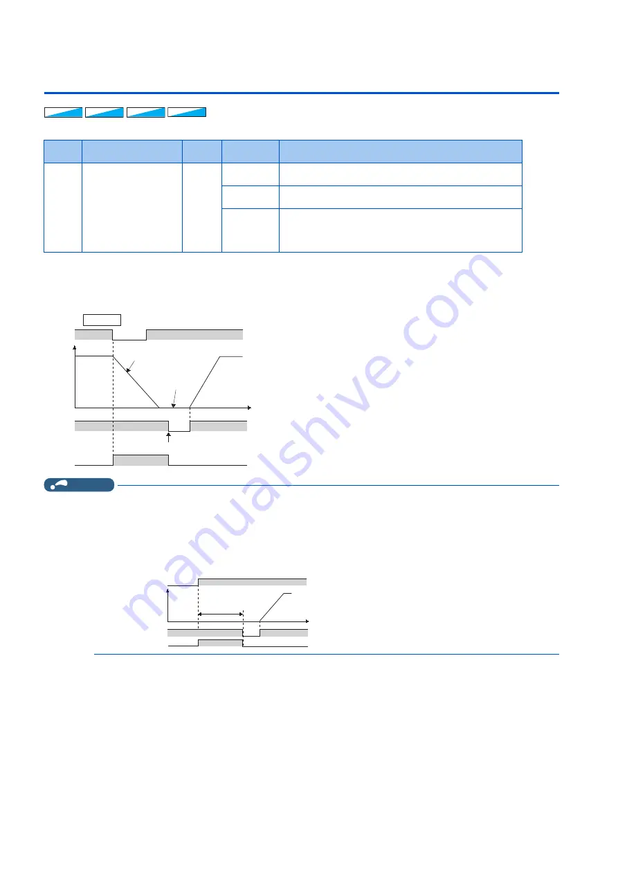
Power failure stop function (Pr.261 = "1")
• Even if power is restored during deceleration triggered by a power failure, deceleration stop is continued after which the
inverter stays stopped. To restart operation, turn the start signal OFF then ON again.
NOTE
• If the automatic restart after instantaneous power failure is selected (
Pr.57 Restart coasting time
≠
"9999") while the power
failure time deceleration stop function is set enabled (
Pr.261
= "1"), the power failure time deceleration stop function is
disabled.
• When the power failure time deceleration stop function is enabled (
Pr.261
= "1"), the inverter does not start even if the power
is turned ON or inverter reset is performed with the start signal (STF/STR) ON. Turn OFF the start signal once and then ON
again to make a start.
Pr.
Name
Initial
value
Setting
range
Description
261
A730
Power failure stop
selection
0
0
The inverter output is shut off at an undervoltage or when a power
failure occurs.
1
The inverter decelerates the motor to a stop at an undervoltage or
when a power failure occurs.
2
The inverter decelerates the motor to a stop at an undervoltage or
when a power failure occurs.
The inverter re-accelerates the motor if the power restores during
the deceleration.
V/F
V/F
V/F
Magnetic flux
Magnetic flux
Magnetic flux Sensorless
Sensorless
Sensorless Vector
Vector
Vector
During deceleration at
occurrence of power failure
During stop at
occurrence of
power failure
STF
Y46
Time
Turn OFF STF once to make acceleration again
Power
supply
Output frequency
Pr.261
=1
STF
Power supply
Time
Y46
Not started as inverter
is stopped due to power
failure
ON
OFF
ON
ON
Output
frequency
Summary of Contents for FR-E800
Page 17: ...16 1 Introduction 1 3 Related manuals MEMO ...
Page 51: ...50 2 Basic Operation 2 8 I O terminal function assignment MEMO ...
Page 89: ...88 3 Parameters 3 4 Parameter list by function group number MEMO ...
Page 135: ...134 5 Speed Control 5 9 Troubleshooting in the speed control MEMO ...
Page 153: ...152 6 Torque Control 6 7 Troubleshooting in torque control MEMO ...
Page 195: ...194 8 E Environment Setting Parameters 8 18 Current average value monitor signal MEMO ...
Page 237: ...236 10 D Operation Command and Frequency Command 10 6 Operation by multi speed setting MEMO ...
Page 339: ...338 13 T Multi Function Input Terminal Parameters 13 9 Start signal operation selection MEMO ...
Page 455: ...454 16 G Control Parameters 16 13 Speed smoothing control MEMO ...


