PU connector
Wiring
3 - 30
3.5 PU
connector
Using the PU connector, you can perform communication operation from a parameter unit
FR-PU07/FR-PA07 or a personal computer. Parameter setting and monitoring can be per-
formed by FR Configurator.
Remove the inverter front cover when connecting.
3.5.1
Connecting the parameter unit
A FR-PU07/FR-PA07 parameter unit can be connected via the FR-A5CBL line to the inverter
and, e.g. then mounted onto a control cabinet to control the inverter from there. The maximum
line length must not exceed 20m.
When connecting, make sure that the plugs in the inverter and in the parameter unit are correctly
engaged. Install the inverter front cover after connecting.
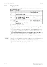
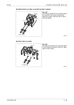
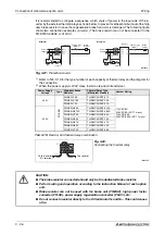
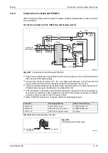
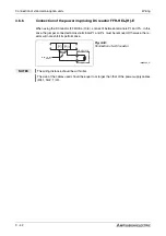
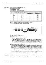
Fig. 3-21:
PU connector
I001990E
I001991
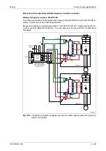
Fig. 3-22:
Connecting a parameter unit using a connection cable
FR-PU07
Cable FR-A5CBL (option)
PU connector
FR-PA07
Summary of Contents for FR-D720S SC EC
Page 2: ......
Page 4: ......
Page 24: ...Description of the case Product checking and part identification 1 4 ...
Page 108: ...Operation panel Operation 4 20 ...
Page 436: ...Setting for the parameter unit and operation panel Parameter 6 286 ...
Page 484: ...Measurements on the main circuit Maintenance and inspection 8 14 ...
Page 504: ...Specification change Appendix A 20 ...
Page 505: ......
Page 506: ......
Page 510: ...Index Appendix A 24 ...
Page 511: ......


