background image

4

3 WIRING

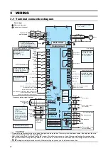
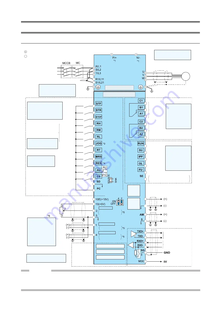
3.1 Terminal connection diagram

CAUTION

 To prevent a malfunction due to noise, keep the signal cables more than 10cm away from the power cables. Also separate the main 

circuit wire of the input side and the output side.

 After wiring, wire offcuts must not be left in the inverter. Wire offcuts can cause an alarm, failure or malfunction. Always keep the 

inverter clean. When drilling mounting holes in an enclosure etc., take care not to allow chips and other foreign matter to enter the 
inverter.

 Set the voltage/current input switch correctly. Different setting may cause a fault, failure or malfunction.

FM

SD

Source logic

Main circuit terminal

Control circuit terminal

Jumper

*2

Earth

*1 Do not connect any options 

to P/+ and N/

.

Motor

*2 To supply power to the

control circuit separately,
remove the jumper across
R1/L11 and S1/L21.

3-phase AC

power supply

Main circuit

Control circuit

Terminal functions vary with 
the input terminal 
assignment.

(

Pr. 178 to Pr. 189

)

Control input signals (No voltage input allowed)

Forward

rotation

start

Reverse

rotation

start

Start self-

holding

selection

High

speed

Middle

speed

Low

speed

Multi-speed selection

Jog mode

Second function selection

Output stop

Reset

Current input selection

Selection of automatic restart after

instantaneous power failure

Contact input common (Sink*)

*3 JOG terminal can be used

as pulse train input
terminal. Use 

Pr. 29

1 to

select JOG/pulse.

24 V DC power supply/max. 100 mA load current

Contact input common (Source*)

*(Common for external power supply transistor)

Frequency setting signal (Analog)

Auxiliary

input

Terminal 4

input

(Current

input)

0–5V DC

0– ±10V DC

4–20mA DC

0 to 10V DC
0 to 20mA DC

0 to ±5V DC

0 to 5V DC
0 to 10V DC

PU
connector

Connector for 
plug-in option 
connection

Option connector 1

Terminating

resistor

*5 Terminal input specifica

tions can be changed by
analog input specifications
switchover
(Pr. 73, Pr. 267).
Set the voltage/current
input switch in the OFF
position to select voltage
input (0 to 5V/0 to10V) and
ON to select current input
(4 to 20mA).

*6 It is recommended to use 1k

, 2W


potentiometer when the frequency 
setting signal is changed frequently.

Relay output 1
(Fault output)

Relay output 2

Running

Instantaneous 
power failure

Up to frequency

Overload

Terminal functions 
vary with the output 
terminal assignment

(

Pr. 195, Pr. 196

)

Terminal functions 
vary with the output 
terminal assignment

(

Pr. 190 to Pr. 194

)

Frequency detection

Open collector output common
Sink/source common

Pulse output

Analog signal output 
(0 to 10VDC)

RS-485 terminals

Data transmission

Data reception

(Permissible load
current 100mA)

Frequency setting

potentiometer

1k

Ω

1/2W

M

3~

*4 AU terminal can be

used as PTC input
terminal.

*5 Voltage/

current 
input switch

Option connector 2

Option connector 3

Relay output

USB
connector

Open collector output

Summary of Contents for FR-A741-11K

Page 1: ...MITSUBISHI ELECTRIC MITSUBISHI ELECTRIC INDUSTRIAL AUTOMATION Frequency Inverter Installation Guideline FR A741 5 5K to 55K Art No 224739 08 04 2009 Version A ...

Page 2: ......

Page 3: ... product until you have a full knowledge of the equipment the safety information and the instructions Please forward this manual to the end user 1 2 3 4 5 6 INSTALLATION OF THE INVERTER AND INSTRUCTIONS 1 OUTLINE DIMENSION DRAWING 3 WIRING 4 PRECAUTIONS FOR THE USEOF THE INVERTER 9 FAILSAFE OF THE SYSTEM WHICH USES THE INVERTER 11 PARAMETER 12 TROUBLESHOOTING 22 APPENDIX 24 7 A ...

Page 4: ... applications please contact your nearest Mitsubishi sales representative Although this product was manufactured under conditions of strict quality control you are strongly advised to install safety devices to prevent serious accidents when it is used in facilities where breakdowns of the product are likely to cause a serious accident Please do not use this product for loads other than three phase...

Page 5: ... wet hands You may get an electric shock When measuring the main circuit capacitor capacity the DC voltage is applied to the motor for 1s at powering off Never touch the motor terminal etc right after powering off to prevent an electric shock Install the inverter on a nonflammable wall without holes so that nobody can touch the inverter heatsink on the rear side etc Mounting it to or near combusti...

Page 6: ...e of the inverter The electronic thermal relay function does not guarantee protection of the motor from overheating Do not use a magnetic contactor on the inverter input for frequent starting stopping of the inverter Use a noise filter to reduce the effect of electromagnetic interference and follow the accepted EMC procedures for proper installation of frequency inverters Otherwise nearby electron...

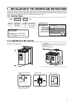
Page 7: ... number 5 5 to 55 Indicate inverter capacity kW Capacity plate example Rating plate example Capacity plate Rating plate Serial number Inverter type Inverter type Input rating Output rating Serial number CAUTION When encasing multiple inverters install them in parallel as a cooling measure Install the inverter vertically vertical Refer to the clearances below Ambient air temperature and humidity Cl...

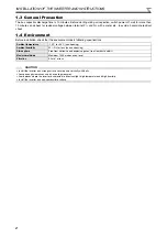
Page 8: ...environment meets following specifications Ambient temperature 10 C to 50 C non freezing Ambient humidity 90 RH or less non condensing Atmosphere Free from corrosive and explosive gases free from dust and dirt Maximum altitude Maximum 1000 m above sea level Vibration 5 9m s or less CAUTION Install the inverter on a strong surface securely and vertically with bolts Leave enough clearances and take ...

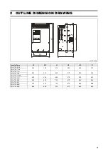
Page 9: ... 5 5K 250 190 470 454 425 270 FR A741 7 5K FR A741 11K 300 220 600 575 540 294 FR A741 15K FR A741 18 5K 360 260 600 575 535 320 FR A741 22K FR A741 30K 450 350 700 675 635 340 FR A741 37K 470 370 700 670 630 368 FR A741 45K FR A741 55K 600 480 900 870 830 405 W1 W H1 H D H2 ...

Page 10: ...input common Sink 3 JOG terminal can be used as pulse train input terminal Use Pr 291 to select JOG pulse 24 V DC power supply max 100 mA load current Contact input common Source Common for external power supply transistor Frequency setting signal Analog Auxiliary input Terminal 4 input Current input 0 5V DC 0 10V DC 4 20mA DC 0 to 10V DC 0 to 20mA DC 0 to 5V DC 0 to 5V DC 0 to 10V DC PU connector...

Page 11: ... of the inverter Doing so will damage the inverter Connect the motor to U V W At this time turning on the forward rotation switch signal rotates the motor in the clockwise direction when viewed on the motor shaft Screw size M4 Jumper Charge lamp Motor Power supply M 3 L1 L2 L3 Screw size M4 Jumper Charge lamp Power supply Screw size M5 Motor Screw size M4 M 3 L1 L2 L3 Screw size M4 Charge lamp Jum...

Page 12: ...0K 22 22 14 4 21 1 4 21 1 25 25 16 FR A741 37K 22 22 14 4 21 1 4 21 1 25 25 16 FR A741 45K 38 38 22 1 42 4 2 33 6 50 50 25 FR A741 55K 60 60 22 1 0 42 4 53 4 50 50 25 1 The recommended cable size is that of the HIV cable 600V class 2 vinyl insulated cable with continuous maximum permissible temperature of 75 C Assumes that the ambient temperature is 50 C or less and the wiring distance is 20m or l...

Page 13: ...llowing measures Use a 400V class inverter driven insulation enhanced motor and set frequency in Pr 72 PWM frequency selection according to wiring length Limiting the voltage rise speed of the frequency inverter output voltage dU dT If the motor requires a rise speed of 500V µs or less you must install a filter in the output of the inverter Please contact your Mitsubishi dealer for more details 3 ...

Page 14: ...ignals are micro currents Do not apply a voltage to the contact input terminals e g STF of the control circuit Always apply a voltage to the alarm output terminals A B C via a relay coil lamp etc It is recommended to use the cables of 0 3mm to 0 75mm gauge for connection to the control circuit terminals If the cable gauge used is 1 25mm or more the front cover may be lifted when there are many cab...

Page 15: ...r arrester to be damaged If any of the above devices is installed immediately remove it Before starting wiring or other work after the inverter is operated wait for at least 10 minutes after the power supply has been switched off and check that there are no residual voltage using a tester or the like The capacitor is charged with high voltage for some time after power off and it is dangerous A sho...

Page 16: ...city to have enough allowance for current Make sure that the specifications and rating match the system requirements A motor with encoder is necessary for vector control In addition connect the encoder directly to the backlash free motor shaft An encoder is not necessary for real sensorless vector control When the motor speed is unstable due to change in the frequency setting signal caused by elec...

Page 17: ...t and consider the backup system such as checking up as below according to the level of importance of the system Check the motor running and motor current while the start signal is input to the inverter by comparing the start signal to the inverter and detected speed of the speed detector or detected current of the current detector Note that the motor current runs as the motor is running for the p...

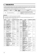
Page 18: ...njection brake operation frequency 0 to 120Hz 9999 3Hz 11 DC injection brake operation time 0 to 10s 8888 0 5s 12 DC injection brake operation voltage 0 to 30 4 2 1 13 Starting frequency 0 to 60Hz 0 5Hz 14 Load pattern selection 0 to 5 0 15 Jog frequency 0 to 400Hz 5Hz 16 Jog acceleration deceleration time 0 to 3600 360s 0 5s 17 MRS input selection 0 2 4 0 18 High speed maximum frequency 120 to 40...

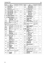
Page 19: ...mode selection 0 1 2 3 4 6 7 0 80 Motor capacity 0 4 to 55kW 9999 9999 81 Number of motor poles 2 4 6 8 10 12 14 16 18 20 9999 9999 82 Motor excitation current 0 to 500A 9999 9999 Parameter Name Setting Range Initial Value 83 Rated motor voltage 0 to 1000V 400V 84 Rated motor frequency 10 to 120Hz 60Hz 89 Speed control gain magnetic flux vector 0 to 200 9999 9999 90 Motor constant R1 0 to 50Ω 9999...

Page 20: ... 106 108 110 4 145 PU PU display language selection 0 to 7 1 Parameter Name Setting Range Initial Value 148 Current detection Stall prevention level at 0V input 0 to 220 150 149 Stall prevention level at 10V input 0 to 220 200 150 Output current detection level 0 to 220 150 151 Output current detection signal delay time 0 to 10s 0s 152 Zero current detection level 0 to 220 5 153 Zero current detec...

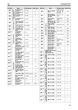
Page 21: ...00 100 243 Terminal 1 added compensation amount terminal 4 75 244 Cooling fan operation selection 0 1 1 Parameter Name Setting Range Initial Value 245 Slip compensation Rated slip 0 to 50 9999 9999 246 Slip compensa tion time con stant 0 01 to 10s 0 5s 247 Constant power range slip com pensation selec tion 0 9999 9999 250 Stop selection 0 to 100s 1000 to 1100s 8888 9999 9999 251 Output phase loss ...

Page 22: ... waiting time setting 0 to 150ms 9999 9999 338 Communication operation com mand source 0 1 0 339 Communication speed command source 0 1 2 0 340 Communication startup mode selection 0 1 2 10 12 0 Parameter Name Setting Range Initial Value 341 RS 485 communication RS 485 commu nication CR LF selection 0 1 2 1 342 Communication EEPROM write selection 0 1 0 343 Communication error count 0 350 2 Orient...

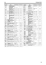
Page 23: ... Range Initial Value 450 Second motor constants Second applied motor 0 to 8 13 to 18 30 33 34 40 43 44 50 53 54 9999 9999 451 Second motor control method selection 10 11 12 20 9999 9999 453 Second motor capacity 0 4 to 55kW 9999 9999 454 Number of sec ond motor poles 2 4 6 8 10 9999 9999 455 Second motor excitation cur rent 0 to 500A 9999 9999 456 Rated second motor voltage 0 to 1000V 400V 457 Rat...

Page 24: ...eter for manufacturer setting Do not set 548 Parameter Name Setting Range Initial Value 549 Communication Protocol selec tion 0 1 0 550 NET mode opera tion command source selection 0 1 9999 9999 551 PU mode opera tion command source selection 1 2 2 555 Current average value monitor Current average time 0 1 to 1 0s 1s 556 Data output mask time 0 0 to 20s 0s 557 Current average value monitor signal ...

Page 25: ...que control inte gral time 2 0 to 500ms 9999 9999 836 Torque setting filter 2 0 to 5s 9999 9999 837 Torque detection filter 2 0 to 0 1s 9999 9999 Parameter Name Setting Range Initial Value 840 2 Torque bias Torque bias selection 0 to 3 9999 9999 841 2 Torque bias 1 600 to 1400 9999 9999 842 2 Torque bias 2 843 2 Torque bias 3 844 2 Torque bias filter 0 to 5s 9999 9999 845 2 Torque bias oper ation ...

Page 26: ...e 0 1 to 1000h 9999 9999 898 Power saving cumulative moni tor clear 0 1 10 9999 9999 899 Operation time rate estimated value 0 to 100 9999 9999 Parameter Name Setting Range Initial Value C0 900 3 FM terminal calibration C1 901 3 AM terminal calibration C2 902 3 Terminal 2 frequency setting bias frequency 0 to 400Hz 0Hz C3 902 3 Terminal 2 frequency setting bias 0 to 300 0 125 903 3 Terminal 2 freq...

Page 27: ...Setting Range Initial Value 990 PU buzzer control 0 1 1 991 PU contrast adjustment 0 to 63 58 Pr CL Parameter clear 0 1 0 ALLC All parameter clear 0 1 0 Er CL Faults history clear 0 1 0 Pr CH Parameter copy 0 1 2 3 0 Parameter Name Setting Range Initial Value 1 Differ according to capacities 7 5K or less 11K or more 2 Setting can be made only when the FR A7AP is mounted 3 The parameter number in p...

Page 28: ...t be determined prior to switching on again as a recurrence of such faults at short intervals can lead to premature aging of components or even the complete breakdown of the device After the cause of the fault has been found and corrected the inverter can be reset and operations continue Inverter fault or alarm indications are roughly divided as below Error Message A message regarding operational ...

Page 29: ...c thermal relay function E FIN Fin overheat E IPF Instantaneous power failure E UVT Undervoltage E ILF Input phase failure E OLT Stall prevention E GF Output side earth ground fault overcurrent E LF Output phase loss E OHT External thermal relay operation to to Fault E PTC PTC thermistor operation E OPT Option alarm E OP3 Communication option alarm to E 1 to E 3 Option fault E PE Parameter storage...

Page 30: ...rth Connect the equipment to the earth securely Wire the earth terminal independently Do not connect two or more cables to one terminal Use the cable sizes on page 6 at the ambient temperature indicated there If the ambient temperature is different select appropriate wire according to EN60204 ANNEX C TABLE 5 When tightening the screw be careful not to damage the threads For use as a product compli...

Page 31: ...more than 5 kA rms symmetrical amperes 528 V maximum FR A741 K 5 5 7 5 11 15 018 5 22 30 37 45 55 Rated voltage V 480V or more Fuse maximum allowable rating A 40 70 80 90 110 150 175 200 250 300 CAUTION Protective function by electronic thermal relay function is reset by inverter power reset and reset signal input Avoid unnecessary reset and power off When multiple motors are operated by a single ...

Page 32: ...codes For installation in Canada branch circuit protection must be provided in accordance with the Canada Electrical Code and any applicable provincial codes As specified UL Class T fuses or any faster acting fuse with the appropriate rating must be employed Maximum allowable rating by US National Electrical Code Exact size must be chosen for each installation A 2 3 Short circuit ratings Suitable ...

Page 33: ...by inverter power reset and reset signal input Avoid unnecessary reset and power off When multiple motors are operated by a single inverter protection cannot be provided by the electronic thermal relay function Install an external thermal relay to each motor When the difference between the inverter and motor capacities is large and the setting is small the protective characteristics of the electro...

Page 34: ...28 APPENDIX ...

Page 35: ......

Page 36: ...35 Riga Phone 371 0 784 2280 Fax 371 0 784 2281 LITHUANIA Beijer Electronics UAB Savanoriu Pr 187 LT 02300 Vilnius Phone 370 0 5 232 3101 Fax 370 0 5 232 2980 EUROPEAN REPRESENTATIVES MOLDOVA INTEHSIS srl bld Traian 23 1 MD 2060 Kishinev Phone 373 0 22 66 4242 Fax 373 0 22 66 4280 NETHERLANDS Koning Hartman b v Haarlerbergweg 21 23 NL 1101 CH Amsterdam Phone 31 0 20 587 76 00 Fax 31 0 20 587 76 05...

Reviews: