


533
SELECTION
S
E
LECTION
3
value of class 3 equipment earthing (protective
grounding) and generally there are no restrictions
on the rated sensitivity current. Hence, select the
rated sensitivity current from among 15, 30, 100,
200 and 500mA, and conduct protective earthing
so that the permissible contact voltage is not
exceeded.
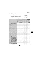
(3) Characteristics and operational
instructions for the ground fault
interrupter
1) When operating the low acoustic noise (high
carrier frequency) inverter operation, the leakage
current increases in harmonic current component
as compared to a conventional inverter, resulting
in a larger continuous leakage current. When a
recent ground fault interrupter provided with a
harmonic eliminating circuit to prevent malfunction
is used, selection can be made in the same way
as in the conventional inverter (see page 531).
When performing low acoustic noise (high carrier
frequency) inverter operation with the ground fault
interrupter which is not provided with the
harmonic eliminating circuit, a malfunction may
occur. Therefore, it is recommended to use the
ground fault interrupter provided with the
malfunction preventing circuit.
2) Install the groundfault interrupter in the power
supply side of the inverter. (Proper operation is
not performed if it is installed in the load side)
3) If a ground fault occurs in the power supply side of
the inverter, the ground fault interrupter operates
properly, posing not problem.
If a ground fault occurs in the load side of the
inverter, the sensitivity current of the ground fault
interrupter may change depending on the
operating status (output frequency) of the inverter.
This is mainly because the waveform of the
ground fault current is not a sinusoidal wave but
an AC non-sinusoidal wave including harmonic
and DC components.
4) In Japan installation of an earth leakage circuit
breaker is mandated by the "Technological
baseline related to electrical equipment, article
41" and "Occupational safety and health rules,
articles 333, 334". For full information, refer to the
corresponding ordinances.
3.6.6
Relays
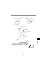
3.6.7
Start/stop switch
Use a low-current switch to prevent a contact fault.
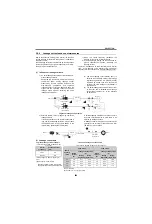
• 200V class
Class D grounding
(grounding resistance 100 or less)
• 400V class
Class C grounding
(grounding resistance 10 or less)
• When the power transformer is of
connection
neutral point earthing type, use special class C
grounding (10
or less) because the sensitivity
current is blunted with respect to an earth fault on the
secondary side of the inverter.
Relays used in the control circuit, e.g. inputs STF,
STR, 10, 2, 5 etc.
Use small-signal relays (twin contact) to prevent a contact fault.
Omron: Type G2A, Fuji: Type No. 473, No. 474
Relays used with outputs RUN, SU etc.
Use small relays of 12VDC or 24VDC, 100mA or less.
18
11.5
12.2
2.8
0.5
7.1
13.7
4.5
7.9
4.7
13
4.7
21
Hole 1.1 2
Switch example (Nippon Kaiheiki )
Single-pole, double-throw switch (M-2012J-G)
A
Panel drilling diagram
(Unit: mm)
Dimension A
+0.3
0
+0.3
0
Without bezel
With bezel
12.5 n
12.5+15.8(n 1)
15.9
+0.15
0.1
Summary of Contents for FR-A700 Series
Page 245: ...279 2 PARAMETER PARAMETER MEMO ...
Page 440: ...474 PARAMETER MEMO ...
Page 522: ...556 SELECTION MEMO ...


