


529
SELECTION
S
E
LECTION
3
3.6.2
Magnetic contactor (MC)
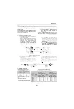
(1) Inverter's primary side magnetic contactor
(MC)
On the inverter's primary side, it is recommended to
provide an MC for the following purposes. Refer to
page 34.
1) To release the inverter from the power supply
when the inverter protective function is activated
or the drive becomes faulty (e.g. emergency stop
operation).
When cycle operation or heavy-duty operation is
performed with an optional brake resistor
connected, overheat burnout of the brake resistor
can be prevented if a regenerative brake
transistor is damaged due to insufficient heat
capacity of the brake resistor and excess
regenerative brake duty.
2) To prevent any accident due to an automatic
restart at restoration of power after an inverter
stop made by a power failure. For
,
when an instantaneous power failure is 15ms or
longer, instantaneous power failure protection is
activated to prevent the inverter from
automatically restarting when power is restored.
When a power failure is longer than about 100ms,
the inverter is therefore restarted automatically if
the RUN signal is ON.
3) To rest the inverter for an extended period of time
The control power supply for inverter is always
running and consumes a little power. When
stopping the inverter for an extended period of
time, powering OFF the inverter will save power
slightly.
4) To separate the inverter from the power supply to
ensure safety of maintenance/inspection work.
Since the inverter primary MC is used for the
above purposes, select the MC which conforms to
JEM1038-AC1 class. When making an
emergency stop during running, select the MC
which conforms to JEM1038-AC3 class to the
inverter input side current .
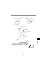
(2) Inverter secondary side magnetic
contactor
Refer to page 37 for details of the turn-ON condition
of a magnetic contactor provided between the
inverter and motor.
1) Switch between bypass operation and inverter
operation.
In this case, the commercial power supply MC
and inverter output circuit MC must be magnetic
contactors with electrical and mechanical
interlocks and the two MCs must be designed not
to turn on at the same time. The transistors will be
damaged if the commercial power is applied to the
inverter output terminals. Select the MC which
has a sufficient capacity for the inverter output
current (JEM 1038-AC Class 3 or higher). Take
special care so that the inverter is not connected
with the commercial power supply by an arc
generated when the current is shut off.
2) To use one inverter with several motors by
switching the inverter-driven motors from one to
another.
The MC may be switched OFF during stop.
In a sequential start, select the MC which meets
JEM1038-AC Class 3 or higher in consideration of
the switching life.
3.6.3
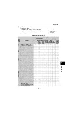
Thermal relay
A thermal relay is generally used to protect a general-purpose
motor. The current flowing in the general-purpose motor driven
from an inverter is about 10% larger than that flowing in the
motor driven when from a commercial power supply.
For this reason, set the thermal relay to 1.1 times greater than
the current value for use with the commercial power supply.
Note that since the standard motor is designed for use are any
of the three ratings of 200V/50Hz, 200V/60Hz and 220V/60Hz,
the temperature rise of the motor may exceed the permissible
value even when the load current is within the rated value
when the motor is continuously run at the rated torque of 50Hz
or at low speed. Therefore, select the motor capacity so that
the load torque is less than the
allowable motor torque
as
indicated in page 491.
The inverters are incorporated with an electronic thermal relay
to protect the motor from overload in the low speed range.
Therefore, a thermal relay need not be provided unless:
z
Two or more motors are run by one inverter
z
A special motor is run. In this case, provide a heat-operated
thermal relay.
A700
F700
* The MC may be switched ON/OFF to start/stop the inverter.
However, since repeated inrush currents at power ON will
shorten the life of the converter circuit (
switching
life is about 1000,000 times (about 500,000 times for the
200V class 37k or more)), frequent starts and stops must
be avoided. Turn ON/OFF the inverter start controlling
terminals (STF, STR) to run/stop the inverter.
A700
Summary of Contents for FR-A700 Series
Page 245: ...279 2 PARAMETER PARAMETER MEMO ...
Page 440: ...474 PARAMETER MEMO ...
Page 522: ...556 SELECTION MEMO ...


