


524
SELECTION
3.5.4
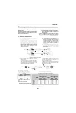
Leakage currents and countermeasures
Due to capacitances existing in the inverter I/O lines and
ground, leakage currents flow through them, in addition to
the motor current.
These leakage currents are determined by the magnitudes
of switching frequency (fc) (carrier frequency) and line-to-
line and to-ground capacitances:
1) When the carrier frequency increases, the
leakage current of the inverter increases.
2) If the wiring length is large, the line-to-line and to-
ground capacitances increase, increasing the
leakage current.
Therefore, independent of the manufacture and inverter
type, a low acoustic noise inverter using high-carrier
frequency PWM control tends to increase leakage current.
(1) Influence of leakage currents
1) An earth leakage circuit breaker is actuated by to-
ground leakage currents
Compared to a case where a motor is driven by a
commercial power supply, leakage current
produced by inverter operation includes more
high-frequency components and to-ground
leakage current in this high frequency band are
higher than the operating current of the earth
leakage circuit breaker, actuating the earth
leakage circuit breaker.
(a) The earth leakage circuit breaker (NV1) is
actuated when leakage current flow through
to-ground capacitances C in paths A) and B)
indicated by dotted lines and exceed the
setting of the earth leakage circuit breaker in
the same line.
(b) The earth leakage circuit breaker NV2 or NV1
in the other line is actuated when leakage
current flows in paths
C)
,
D), E),
etc. indicated
by dotted line.
2) External thermal relay is tripped by line-to-line
leakage currents
If the wiring distance on the inverter output side is
long, line-to-line leakage currents
A)
may increase
the effective value of the current flowing in the
thermal relay, operating the thermal relay.
A smaller-capacity model whose rated current is
less than several amperes is more liable to be
affected by leakage currents.
A leakage current
B)
may produce a several volts
potential at the terminal of the radio noise filter
(FR-BIF) but it is not a fault.
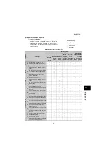
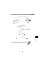
(2) Leakage current data
Power
NV1
NV2
Earth leakage
circuit breaker
C
C
Motor
Motor
Inverter
A
B
D
C
E
Earth leakage
circuit breaker
To-ground leakage current paths
Power
MCCB
FR-BIF
Inverter
Thermal relay
Line-to-line
capacitance
Motor
A
B
To-ground leakage current example
Line-to-line leakage current example
(Total current measured at 100kHz or less
using FFT.)
Total current measured at 100kHz or less using FFT.
Carrier
Frequency
Leakage Current
(mA)
Motor
Capacity
(kW)
200V Class
400V Class
2kHz
90
Rated
current
(A)
Leakage current value
(A)
Rated
current
(A)
Leakage current value
(A)
14.5kHz
210
Wiring
length 50m
Wiring
length 100m
Wiring
length 54m
Wiring
length 100m
(running frequency: 60Hz, wiring length:
20m)
(Motor capacity: 3.7kW 4-pole)
0.4
1.8
0.31
0.50
1.1
0.62
1.00
0.75
3.2
0.34
0.53
1.9
0.67
1.05
1.5
5.8
0.37
0.56
3.5
0.74
1.12
2.2
8.2
0.40
0.59
4.1
0.80
1.18
(Carrier 14.5kHz)
(Wire used: 3.5 4-core type cable)
* Leakage currents in commercial power
supply operation are approximately 1mA.
Summary of Contents for FR-A700 Series
Page 245: ...279 2 PARAMETER PARAMETER MEMO ...
Page 440: ...474 PARAMETER MEMO ...
Page 522: ...556 SELECTION MEMO ...


