380
PARAMETER
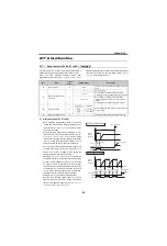
(3) Fault definition [Pr. 875]
When [
Pr. 875
= 0], the inverter immediately shut off
output at fault occurrence and outputs faults.
When [
Pr. 875
= 1] and external thermal relay
(E.OHT), motor overload (electronic thermal relay
function) (E.THM) or PTC thermistor (E.PTC) is
activated, turning ON the alarm output 2 signal (ER)
starts the motor to decelerate and provides a fault
after deceleration to a stop.
When the ER signal turns ON, decrease load, etc. to
allow the inverter to decelerate.
At occurrence of a fault other than E.OHT, E.THM
and E.PTC, the inverter trips immediately and a fault
signal is output.
Set 97 (positive logic) or 197 (negative logic) in [
Pr.
190 to Pr. 196 Output terminal function selection
] and
assign the ER signal to the output terminal.
This function is invalid during vector control.
The value 0 is recommended for the system in which
the motor continues running without deceleration due
to a large torque on the load side.
2.17.4 Input/output phase loss protection selection [Pr. 251, 872]
(common)
You can disable the output phase loss protection function
that stops the inverter output if one of the inverter output
side (load side) three phases (U, V, W) is lost.
The input phase loss protection function of the inverter
input side (R/L1, S/L2, T/L3) can also be valid.
(1) Output phase loss protection selection
[Pr. 251]
When [
Pr. 251
= 0], output phase loss protection
(E.LF) becomes invalid.
(2) Input phase loss protection selection [Pr.
872]
When [
Pr. 872
= 1], input phase loss protection
(E.ILF) is provided if a phase loss of one phase
among the three phases is detected for 1s
continuously.
Note that if input phase is lost when [
Pr. 261
≠
0]
in
(power failure stop function valid),
input phase loss protection (E.ILF) is not provided but
power-failure deceleration is made.
When an input phase loss occurs in the R/L1 and S/
L2 phases, input phase loss protection is not
provided but the inverter output is shut off.
If the load is light, lost phase cannot be detected in
because detection is performed
based on the fluctuation of bus voltage. It cannot be
detected under regenerative load either.
Also, input loss protection (E.ILF) may occur when
phase voltage is largely unbalanced among three
phases.
[Pr. 450]
Second
Applied
Motor
[Pr. 9]
Electronic
Thermal
O/L Relay
[Pr. 51]
Second
Electronic
Thermal O/
L Relay
RT = OFF
RT = ON
Fi
rs
t
mo
to
r
S
e
c
ond
mo
to
r
Fi
rs
t
mo
to
r
S
e
c
ond
mo
to
r
9999
0
9999
×
×
×
×
0
×
×
×
×
0.01 to 500
(0.1 to 3600)
×
×
{
9999
Other than
0
9999
{
×
{
×
0
{
×
×
0.01 to 500
(0.1 to 3600)
{
{
Other than
9999
0
9999
×
×
×
×
0
×
×
×
×
0.01 to 500
(0.1 to 3600)
×
×
{
Other than
9999
Other than
0
9999
{
{
0
{
×
×
0.01 to 500
(0.1 to 3600)
{
{
{
... Output current value is used to perform integration processing.
...Output current is assumed as 0A to perform integration processing.
(cooling processing)
×
.....Electronic thermal relay function is not activated.
A700
Output
speed
Alarm output
(ALM, ALM2)
OHT
occurrence
Minor fault
output 2
(ER)
E.OHT
display
ON
ON
When
[
Pr.875
= 1]
common
[Pr. ]
Name
Initial
Value
Setting
Range
Description
251
Output
phase loss
protection
selection
1
0
Without output
phase loss
protection
1
With output
phase loss
protection
872
Input
phase loss
protection
selection
0
1
0
Without input
phase loss
protection
1
With input phase
loss protection
A700 F700
D700
E700
A700
F700
E700
D700
Summary of Contents for FR-A700 Series
Page 245: ...279 2 PARAMETER PARAMETER MEMO ...
Page 440: ...474 PARAMETER MEMO ...
Page 522: ...556 SELECTION MEMO ...


