


229
2
P
ARAM
ETE
R
PARAMETER
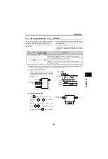
(2) Adjustment of pulse train input and
frequency [
Pr. 385, 386
]
Frequency for zero input pulse can be set using [
Pr.
385 Frequency for zero input pulse
] and frequency at
maximum input pulse can be set using [
Pr. 386
Frequency for maximum input pulse
].
(3) Calculation method of scaling factor of
input pulse [
Pr. 384
]
Maximum input pulse can be calculated from the
following formula using [
Pr. 384 Input pulse division
scaling factor
].
For example, when you want to operate at 0Hz when
pulse train input is zero and operate at 30Hz when
pulse train is 4000 pulse/s, set parameters as below.
2.4.8
Frequency setting by 16 bit digital input (FR-A7AX) [Pr. 300 to 305, 329]
(A700)(F700)(E700)
16bit (12bit) digital input is available for the inverter with a plug-in option FR-A7AX installed and [
Pr. 304
9999
] is set.
For
, using digital input as a torque command is also available. (Refer to page 301)
*
Limit value can be calculated from the following formula.
([
Pr. 386
] - [
Pr. 385
]) 1.1 + [
Pr. 385
]
60Hz
[
Pr.386
]
0Hz
Limit value*
input pulse
(pulse/s)
0
=
Pr.385
]
=
Pr.384
?
400(maximum 100k pulse/s)
Output
frequency
(Hz)
Maximum input pulse
Maximum input pulse (pulse/s) = [
Pr. 384
]
400
[
Pr. 384
] = 10
(maximum input pulse 4000 pulse/s)
[
Pr. 385
] = 0Hz
[
Pr. 386
] = 30Hz
(pulse train limit value is 33Hz)
maximum of 100k pulse/s
detectable pulse = 11.45 pulse/s
(
)
A700
F700 E700
A700
[
Pr.
]
Name
Initial
Value
Setting
Range
Description
Available
Inverters
300
BCD input bias
0Hz
0 to 400Hz Set bias frequency for BCD code input
301
BCD input gain
60Hz
0 to 400Hz Set gain frequency for BCD code input
9999
Digital input value is the output frequency
302
BIN input bias
0Hz
0 to 400Hz Set bias frequency for binary input
303
BIN input gain
60Hz
0 to 400Hz Set gain frequency for binary input
9999
Digital input value is the output frequency
304
Digital input and analog
input compensation
enable/disable
selection
9999
Input selection
Availability of Analog
Input Compensation
*
1
0
3 digits BCD code input
*2
1
12bit binary input
*2
2
3 digits BCD code input
*2
—
3
12bit binary input
*2
4
12bit binary Torque
command value input
*2
—
—
10
4 digits BCD code input
11
16bit binary input
12
4 digits BCD code input
—
13
16bit binary input
14
16bit binary Torque
command value input
—
—
9999
No function
305
Read timing operation
selection
0
0
Data is always read regardless of DY signal.
1
Data is read only when DY signal is ON.
10
Data is always read regardless of DY signal.
With filter at reading.
329
*3
Digital input increments
selection
1
0
Input value increments 10
1
Input value increments 1
2
Input value increments 0.1
3
Input value increments 0.01
*1
Use terminal 1 for analog input compensation.
*2
X12 to X15 signal of plug-in option FR-A7AX is invalid.
*3
Writing during running is unavailable even when [
Pr. 77 = 2
]. When changing the parameter setting, stop the operation.
Also parameter clear is invalid.
A700
F700
E700
Summary of Contents for FR-A700 Series
Page 245: ...279 2 PARAMETER PARAMETER MEMO ...
Page 440: ...474 PARAMETER MEMO ...
Page 522: ...556 SELECTION MEMO ...


