


200
200
PARAMETER
PARAMETER
PA
R
A
M
E
T
E
R
2
Clear p
a
ram
e
te
rs
In
itial value
change l
ist
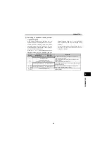
Pr.CL Parameter clear
0, 1
1
0
—
Pr.CL
-
FC
-
-
-
-
-
-
ALLC All parameter clear
0, 1
1
0
—
ALLC
-
FC
-
-
-
-
-
-
Er.CL Faults history clear
0, 1
1
0
—
Er.CL
-
F4
-
-
-
-
-
-
Pr.CH Initial value change list
-
-
-
—
Pr.CH
-
-
-
-
-
-
-
-
*1
Differ according to capacities.
6%: 0.75K or less
4%: 1.5K to 3.7K
3%: 5.5K, 7.5K
*2
Differ according to capacities.
5s: 3.7K or less
10s: 5.5K, 7.5K
*3
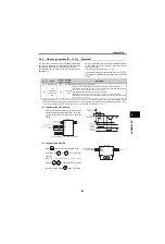
Write is disabled in the communication mode (network operation mode) from the PU connector.
*4
Set this parameter when calibrating the operation panel built-in potentiometer for the FR-E500 series operation panel (PA02)
connected with cable.
*5
The parameter number in parentheses is the one for use with the operation panel (PA02) for the FR-E500 series or parameter
unit (FR-PU04/FR-PU07).
*6
These parameters are communication parameters that are not cleared when parameter clear (all clear) is executed from RS-
485 communication. (Refer to page 441 for RS-485 communication)
Func
ti
on
[Pr.]
Name
Setting Range
Minimum Setting
Increments
Initial Value
Refer to
Page
[Pr.]
Instruction Code
Control Mode-based
Correspondence Table
P
ara
met
e
r
Copy
P
ara
met
e
r
Cl
e
ar
A
ll P
a
ra
m
ete
r
Cl
e
ar
Re
a
d
Wri
te
Ext
en
d
ed
V/F control
General-purpose
magnetic-flux
vector control
Summary of Contents for FR-A700 Series
Page 245: ...279 2 PARAMETER PARAMETER MEMO ...
Page 440: ...474 PARAMETER MEMO ...
Page 522: ...556 SELECTION MEMO ...


