background image

Easy Start Guide

7. How to operate the Inverter from the keypad

Page 7

This guide has been produced by The Inverter Drive Supermarket Ltd.
All content, including but not limited to graphics, text and procedures copyright

The Inverter

©

Drive Supermarket and must not be reproduced or altered without prior written permission.

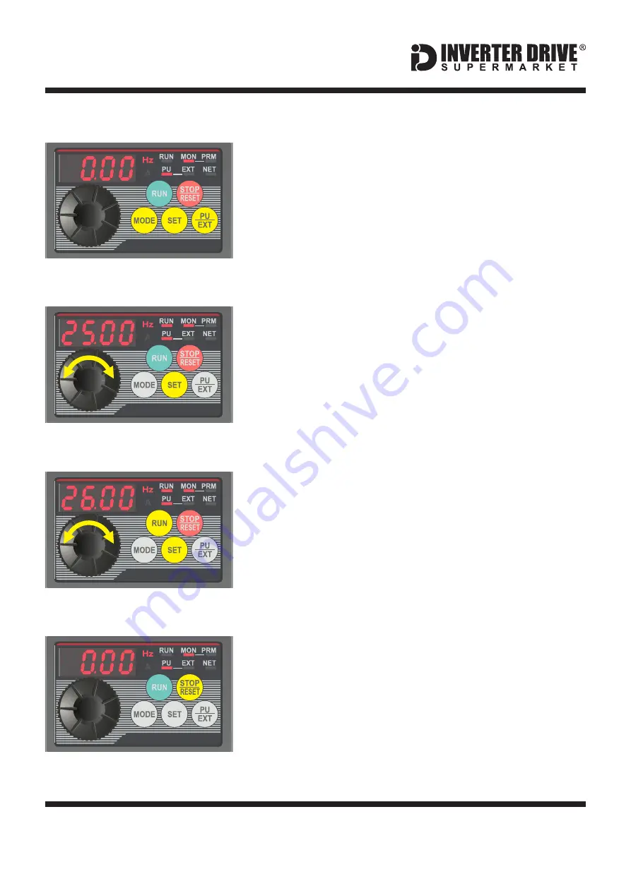
7.3 Press the green “RUN” key to start the motor.

The green key will start the motor. The time taken for the
motor to accelerate to the desired speed (in seconds) is
proportional to parameter Pr. 7. The “RUN” indicator will
illuminate to indicate that the motor is running.

To change the speed whilst the motor is running, rotate the
dial to select the new speed and press “SET” to confirm.
The motor will accelerate or decelerate to the new speed.

Mitsubishi D700-SC Series Inverter

7.1 Select “MON” and “PU” modes.

With the motor stopped, press the “PU/EXT” key
repeatedly to cycle through operation modes until the
“PU” indicator is illuminated and “0.00" is displayed.
Then, press the “MODE” key repeatedly to cycle through
modes until “MON” is illuminated.
Finally, ensure the display is set to “Hz”. If it is set to “A”
(Amps), use the “SET” key to change to “Hz”.

7.2 Set the desired speed.

Rotate the dial to set the desired speed. In this example,
we have set this to 25.00Hz which is half speed for a
standard 50Hz motor.
Press “SET” to save. The display will alternate between
“F” and your selection for 3 seconds before returning to
0.00 (the current speed). When saving, ensure you don’t
accidentally set the display to “A”. If you do, use the
“SET” key to change back to “Hz”.

7.4 Press the red “Stop” key to stop the motor.

The red key will stop the motor. The time taken (in seconds)
to stop the motor is proportional to parameter Pr. 8.

Note: if you would prefer to continually adjust the speed
using the dial (rather than confirming with set each time)
change parameter Pr. 161 to 1.

Summary of Contents for D700-SC

Page 1: ... replacement for the manual issued by the manufacturer Issue 1 20180129 This product is not a safety device All safety considerations including but not limited to Emergency Stop provision should be assessed separately and are outside the scope of this guide Mitsubishi D700 SC Frequency Inverter Easy Start Guide The Mitsubishi D700 SC Frequency Inverter range is available to order from inverterdriv...

Page 2: ...Motor Connections Three Phase Motor Connections Star and Delta Parameters Overview Parameters to set before use How to set a Parameter value How to Operate the Inverter from the keypad How to enable Sensorless Vector mode How to connect and configure a Potentiometer for remote speed control How to connect and configure a Run Forward or Run Reverse switch How to connect and configure a Run Stop swi...

Page 3: ...kW and 2 2kW frame sizes are similar The order of the three output phases determines the direction the motor turns Important Use screened cable between the Inverter and Motor To minimise electromagnetic interference ensure the cable screen is grounded The supply must match the Inverter specification Before commencing confirm that the Inverter and all cables are completely isolated from the power s...

Page 4: ...imilar The order of the three motor phases determines the direction the motor turns The order of the three power phases is unimportant Important Use screened cable between the Inverter and Motor To minimise electromagnetic interference ensure the cable screen is grounded The supply must match the Inverter specification Before commencing confirm that the Inverter and all cables are completely isola...

Page 5: ...de Only two links are required for Star Double up the links if changing from Delta to allow the motor to be changed to back in future The order of the three phases determines the direction the motor turns Note that the cable screen and earth are connected together at the earth terminal Dual voltage induction motors typically include terminal boxes with six points The points can be connected togeth...

Page 6: ...8 for 50 100m or 2 for 100m 15 Pr 79 Operation mode selection Set to to allow control to be switched between Inverter Keypad PU and Terminals EXT 0 Pr 83 Rated motor voltage Rated voltage of the Set to match motor nameplate eg Motor 230 Volts Pr 84 Rated motor frequency Hz Rated frequency of the Set to match motor nameplate eg Motor 50 Hz Pr 160 Extended function display selection Set to to displa...

Page 7: ...arameter setting Press the MODE key repeatedly until the PRM indicator is illuminated The display will show P 0 as shown opposite or the parameter which was last selected 6 3 Select the required parameter Use the dial to scroll through the parameters until the desired parameter is shown In this example we will select parameter 1 as shown in the illustration opposite Press the Set key to select the...

Page 8: ...th the motor stopped press the PU EXT key repeatedly to cycle through operation modes until the PU indicator is illuminated and 0 00 is displayed Then press the MODE key repeatedly to cycle through modes until MON is illuminated Finally ensure the display is set to Hz If it is set to A Amps use the SET key to change to Hz 7 2 Set the desired speed Rotate the dial to set the desired speed In this e...

Page 9: ...ault is 0 Set to for Standard motor 3 Pr 80 Motor capacity kW Default is 9999 not set Set to the motor rated power eg kW 0 75 Pr 82 Motor excitation current Default is 9999 not set Set to approx 30 of motor full load current Pr 96 Auto tuning setting status Default is 0 Set to for general purpose magnetic flux vector control 11 Pr 90 Motor constant R1 Default is 9999 not set Do not change this val...

Page 10: ... on the machine itself A Potentiometer of rating should be 1kOhm used The number of turns depends on the application A single turn Potentiometer is available from The Inverter Drive Supermarket at InverterDrive com 9 2 Connecting the Potentiometer First ensure the Voltage Current Input switch is set to V Voltage A wiring diagram is shown in the illustration opposite The most important connection a...

Page 11: ...itch can be used instead This section explains how to enable 2 wire control with Run Forward Stop Run Reverse commands via a single selector switch The Inverter must be in EXT control mode to operate from the I O terminals Press PU EXT to select 10 2 Connecting the Switch A wiring diagram is shown in the illustration opposite The PC terminal is a common connection for terminals RL RM RH STF and ST...

Page 12: ...tion selection This is the factory default 61 Pr 250 Stop Selection Default is 9999 Set to for Run with Forward Reverse selection 8888 11 1 Parameters to change for remote Run Stop 11 2 Connecting the Switch A wiring diagram is shown in the illustration opposite The PC terminal is a common connection for terminals RL RM RH STF and STR when the jumpers are set in Source the default If the jumpers h...

Page 13: ...Reverse selection 8888 12 1 Parameters to change for remote 3 wire control 12 2 Connecting the Switches The PC terminal is a common connection for terminals RL RM RH STF and STR when the jumpers are set in Source the default If the jumpers have been changed to Sink use SD as the common instead For Run and Stop two suitable pushbuttons should be installed The Run pushbutton should include a Normall...

Page 14: ... is suitably mounted so any heat generated will not affect other equipment Some resistors may include a thermal relay for additional protection It is essential that a resistor of the correct rating is used Consult the product manual issued by the manufacturer or product listing on InverterDrive com for further information Note Some smaller D720S Inverters do not have integrated dynamic braking The...

Page 15: ... setting Press the MODE key repeatedly until the PRM indicator is illuminated The display will show P 0 as shown opposite Note The display may show the last selected parameter instead of P 0 14 3 Select the ALLC parameter Use the dial to scroll through the parameters to ALLC Press the SET key to select parameter ALLC The display will show the initial parameter value of 0 14 4 Change the parameter ...

Reviews: