


Interference avoidance function
6-527
Each parameter is explained in the following section.
(1) Simulated component registration parameter
Parameters listed in
are explained in detail in this section.
Up to eight simulated component types can be registered for each of the robot arm, hand and workpiece.
The last digit of a parameter name indicates the simulated component type.
1) Simulated components for robot arm
<1> Registration section and shape of simulated components: CAVKDA1 to 8
Table 5-31:Simulated component setting parameter (robot arm: CAVKDA1 to 8)
Center position
Using the robot arm installation
face or the rotation center of
each axis as the reference point,
set the simulated component’s
center position as a distance
from that reference point.
Parameters:
Designate the simulated component’s center as a distance from the
Mechanical interface coordinate system
‘s origin point (tip of J3 axis).
Parameters:
Parameters:
Simulated component
size
Set the size of each simulated component as a radius.
Parameters:
Parameters:
Parameters:
Enable/disable for each
simulated component
Set whether to enable/disable a simulated component, and whether to temporarily disable a simulated
component when T/B is enabled.
Note) The simulated hand and workpiece must be disabled during teaching.
Parameters:
Parameters:
Parameters:
Note1) The initial settings for each model are set at the factory.
Parameter
Parameter
name
No. of arrays
No. of characters
Details explanation
Factory setting
Registration
section and
shape of sim-
ulated compo-
nent
(robot arm)
CAVKDA1 to 8
Integer 2
Set the registration section (Jn axis) and shape
of a simulated component. Up to eight simulated
component types can be registered. (Each type
corresponds to the last digit (1 to 8) of the
parameter name.)
1st element: Registration section (Jn axis)
0: Base section
1 to 6: Jn axis
2nd element: Shape
0: a sphere
1: a cylinder
Note) The shape of a simulated component is a
sphere.
RH-3/6/12/20FH
series:
CAVKDA1=0, 1
CAVKDA2=0, 0
CAVKDA3=1, 0
CAVKDA4=2, 0
CAVKDA5=2, 0
CAVKDA6=2, 0
CAVKDA7=2, 0
CAVKDA8=4, 1
Note) The setting
value of RH-
3FH35xx, and
RH-6FH35xx and
RH-12FH55xx is
CAVKDA3=0,0.
RH-3FHR series
CAVKDA1=0, 0
CAVKDA2=1, 1
CAVKDA3=1, 0
CAVKDA4=2, 1
CAVKDA5=2, 1
CAVKDA6=3, 1
CAVKDA7=0, 0
CAVKDA8=0, 0
RV-F series:
CAVKDA1=0, 0
CAVKDA2=0, 1
CAVKDA3=2, 1
CAVKDA4=4, 1
CAVKDA5=5, 0
CAVKDA6=0, 0
CAVKDA7=0, 0
CAVKDA8=0, 0
Note) The setting
value of RV-2F is
CAVKDA2=0,0
CAVKDA4=3,0
CAVKDA5=4,1
CAVKDA6=5,0.
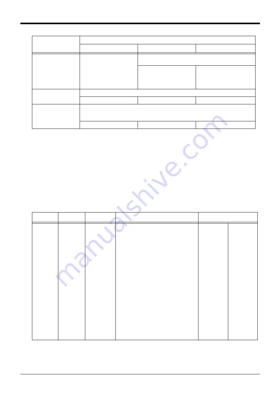
Setting items for
simulated component
Simulated component type
Simulated robot arm
Note1)
Simulated hand
Simulated workpiece


