


Communication Profile Area
Functions
MELSEC-L Series – CANopen
Module ME3CAN1-L
4 – 27
Object 1005
H
: COB-ID SYNC message
In order to guarantee timely access to the network, the SYNC is given a very high priority CAN-ID.
Object 1006
H
: Communication cycle period
The object 1006
H
provides the communication cycle period. This period defines the SYNC interval.
The 32 bit value is given in μs units. The ME3CAN1-L counting resolution is 1 ms, values smaller than
1 ms will set internally to 1 ms, values starting from 1 ms will be divided by 1000. The value 0 disables
the SYNC producing. The module needs to be active NMT Master to produce SYNC messages.
Setting range: 0 to 4, 294, 967, 295
For details about NMT master refer to section 4.8.5.
4.6.7 Node
guarding
This protocol is used to detect remote errors in the network. Each NMT slave serves one response mes-
sage for the node guarding protocol.
The NMT master polls each NMT guarding slave at regular time intervals. This time-interval is called
the guard time and may be different for each NMT slave. The response of the NMT slave contains the
NMT state of that NMT slave. The node lifetime is given by guard time multiplied by lifetime factor. The
node lifetime may be different for each NMT slave. If the NMT slave has not been polled during its life-
time, a remote node error is indicated through the NMT service life guarding event. A remote node
error is indicated through the NMT service node guarding event if:
–
the NMT master does not receive the confirmation after the RTR within the node life time,
–
the response of the NMT guarding slave state does not match the expected state,
–
the NMT guarding slave did not receive the NMT master RTR polling for time set in 100C
H
and
100D
H
.
If a remote error occurred previously but the errors in the guarding protocol have disappeared, it will
be indicated that the remote error has been resolved through the NMT service node guarding event
and the NMT service life guarding event.
If Heartbeat is activated, the Node guarding settings will be ignored.
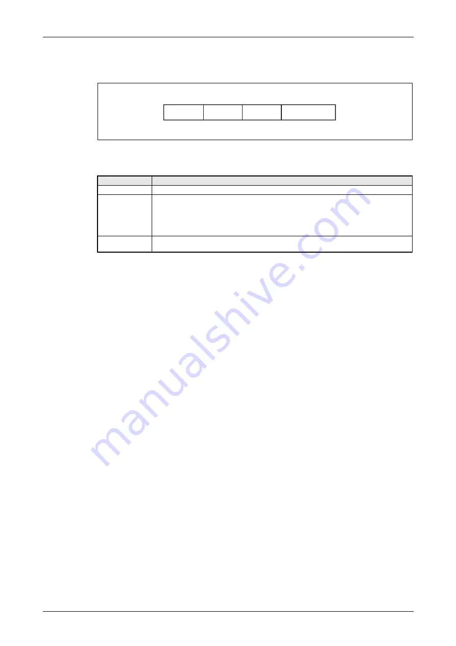
Fig. 4-15:
Bit allocation for object 1005
H
: COB-ID SYNC message
Bit/Item
Description
X
Do not care
gen.
Bit = 0: Don't generate SYNC message
Bit = 1: Generate SYNC message
NOTES:
앫
The device needs to be active NMT master to produce SYNC messages.
앫
Before activating SYNC generation, the communication cycle period has to be set up.
11-bit CAN-ID
11-bit CAN-ID of the CAN base frame.
Refer to section 4.6.1.
Tab. 4-20:
Description for object 1005
H
: COB-ID SYNC message
Bit 31
11-bit CAN-ID
Bit 30
Bit 10 ... Bit 0
0
H
X
gen.
Bit 29 ... Bit 11
Summary of Contents for CANopen ME3CAN1-L
Page 2: ......
Page 4: ......
Page 6: ......
Page 10: ...IV ...
Page 18: ...Abbreviations and Generic Terms Overview MELSEC L Series CANopen Module ME3CAN1 L 1 4 ...
Page 22: ...System Configuration System Equipment 2 4 MITSUBISHI ELECTRIC ...
Page 162: ...Programming Layer 2 Communication 7 24 MITSUBISHI ELECTRIC Program Fig 7 24 Example Program 1 ...
Page 164: ...Programming Layer 2 Communication 7 26 MITSUBISHI ELECTRIC Fig 7 26 Example Program 3 ...
Page 166: ...Programming Layer 2 Communication 7 28 MITSUBISHI ELECTRIC Fig 7 28 Example Program 5 ...
Page 178: ...Layer 2 Communication Programming MELSEC L Series CANopen Module ME3CAN1 L 7 40 ...
Page 184: ...Troubleshooting Error Code and Error Message Summary 8 6 MITSUBISHI ELECTRIC ...
Page 187: ......


