


Detailed Description of the Module
Buffer Memory Details: CANopen
Mode
3 – 16
MITSUBISHI ELECTRIC
3.5.3
Save/Restore Configuration (Un\G22)
This buffer memory specifies two bits that allow to restore the factory default configuration in the buf-
fer memory and to store the buffer memory configuration into the Flash ROM. To execute the request,
please set Y(n+1)F to ON (refer to section 3.3.2).
Both bits will be reset automatically if the restore or save procedure is completed, and X(n+1)F will
turn ON.
3.5.4
Baud Rate (Un\G24)
In Un\G24 the baud rate is set. The current baud rate can be found in Un\G37.
Bit
Description
0
Bit = 1: Save configuration to Flash ROM
1
Bit = 1: Restore factory default configuration (not saved to Flash ROM)
2–15
Reserved
Tab. 3-9:
Assignment of the bits in buffer memory address Un\G22
NOTES
If both bit 0 and bit 1 are set simultaneously the buffer memory and Flash ROM will be reset to the
factory defaults.
If only bit 1 is set, factory default values are written to the configuration buffer memory but not
stored in the Flash ROM. In order to store changes made to the configuration buffer memory, set
Un\G22 bit 0 after changing the configuration.
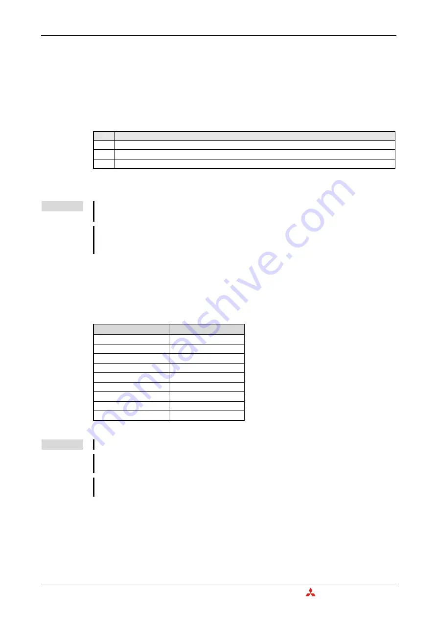
Value in Un\G24
Baudrate
Tab. 3-10:
Settings for the baud rate
10
10 kbps
20
20 kbps
50
50 kbps
100
100 kbps
125
125 kbps
250
250 kbps
500
500 kbps
800
800 kbps
1000
1000 kbps
NOTES
The baud rate must be equal for all nodes in the network.
The new value needs to be stored by Un\G22. Then Y(n+1)F has to be turned ON and the module
has to be restarted to make the new setting effective.
At low baud rates a too fast data exchange and/or high bus load can result in a transmission data
queue overflow error (bit 8 in Un\G29, refer to section 3.5.7).
Summary of Contents for CANopen ME3CAN1-L
Page 2: ......
Page 4: ......
Page 6: ......
Page 10: ...IV ...
Page 18: ...Abbreviations and Generic Terms Overview MELSEC L Series CANopen Module ME3CAN1 L 1 4 ...
Page 22: ...System Configuration System Equipment 2 4 MITSUBISHI ELECTRIC ...
Page 162: ...Programming Layer 2 Communication 7 24 MITSUBISHI ELECTRIC Program Fig 7 24 Example Program 1 ...
Page 164: ...Programming Layer 2 Communication 7 26 MITSUBISHI ELECTRIC Fig 7 26 Example Program 3 ...
Page 166: ...Programming Layer 2 Communication 7 28 MITSUBISHI ELECTRIC Fig 7 28 Example Program 5 ...
Page 178: ...Layer 2 Communication Programming MELSEC L Series CANopen Module ME3CAN1 L 7 40 ...
Page 184: ...Troubleshooting Error Code and Error Message Summary 8 6 MITSUBISHI ELECTRIC ...
Page 187: ......


