20-497
20-497
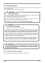
20.3.3. Causes of tact time deviation
With this software, you can use the simulation function to calculate the robot movement tact time.
However, the calculated tact time varies with the performance and load status of the computer used, and will not
completely match the actual robot operating time (tact time).
Use this function as a rough yardstick for tact time study.
Also, there are the following causes of tact time calculation results deviating from actual robot tact time.
(1) An application other than "program editing" of this software is running.
This software's tact time calculation has parts that are processed on the computer in the background. For
example, if you are working running an application such as a Word document that is saved automatically, the
background processing for this software will take more time and sometimes the correct tact time will not be
calculated. The tact time will increase.)
When calculating the tact time with this software, first close other applications.
Also, in this software itself, first close all the screens except "Program edit".
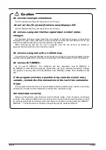
(2) Using commands that depend on the robot main unit status and external equipment.
There is no connection with the robot main unit or external equipment in this software's tact time calculation.
Therefore, commands that are executed by communicating with such equipment are executed as if ideal
information were sent from that equipment. Therefore, the calculated cycle time will be shorter than the
actual cycle time.
The commands to which this applies are shown in the following table.
Function
Command
Explanation
1
Positioning
completion wait
FINE
Monitors the robot's status until it
reaches the target position.
2
Compliance
CMP JNT/POS/TOOL/OFF
CMPG
Monitors external force on the robot.
3
Collision detection
COLCHK
、
COLLVL
Monitors external force on the robot.
4
Servo control
SERVO ON/OFF
Monitors the servo amp status
For example, if the servo On command is executed in the program, the actual robot takes a few seconds, but
the simulation requires almost no time at all (500 ms or less). To calculate the tact time precisely, write the
program using only move commands and none of the previously mentioned commands. If you are executing
a program you already have, either comment out such commands or extract and use just the part you want
to measure.
(3) Using functions that depend on the CPU processing speed and OS.
The tact time calculation in this software runs on Windows, but the robot controller control software runs on a
real-time OS, so the internal operations are different. For example, in the real-time OS, the tact time may be
increased by the postponement of calculations with a high load that could not be fully processed, but in this
software's tact time calculations, such an increase in the tact time cannot be calculated. Therefore, if you use
the following high-load functions, the calculated tact time may be a few percent less than the actual tact time.
The commands to which this applies are shown in the following table.
Function
Cause of increased processing on actual robot
1
CC-Link
Because there is more signal processing with the CC-Link
option than without it
2
Multi tasking
Because multiple robot programs are executed at the same
time
3
Added axes
Because of the need to control the additional axes
4
Maximum
acceleration/deceleration control
Because the optimum movement for the robot load is
calculated
5
Collision detection
Because processing to detect collisions is executed (*1)
6
Maintenance forecast
Because the processing time is longer when the maintenance
forecasting information collection level is raised (*1)
In tact time calculation, the same results are calculated as for
information collection level 1 (the factory default setting).
(*1) On actual robots, the tact time is roughly 3-10% longer.
By changing a robot program to eliminate the above factors, you can reduce the
difference between the simulation tact time and that on the actual robot. However,
because the simulation executes the next movement command without waiting for
Summary of Contents for 3F-14C-WINE
Page 84: ...8 84 8 84 Figure 8 21 Parameter transfer procedure 1 2 2 ...
Page 393: ...18 393 18 393 Figure 18 1 Starting the Oscillograph ...
Page 413: ...18 413 18 413 Figure 18 24 Output to Robot program Selection ...
Page 464: ...18 464 18 464 Figure 18 72 Starting the Tool automatic calculation ...
Page 545: ...21 545 21 545 Figure 21 55 Hide display of user mechanism ...
Page 624: ...24 624 24 624 Figure 24 4 Document output example ...

