15-331
15-331
15.1.4. ABS
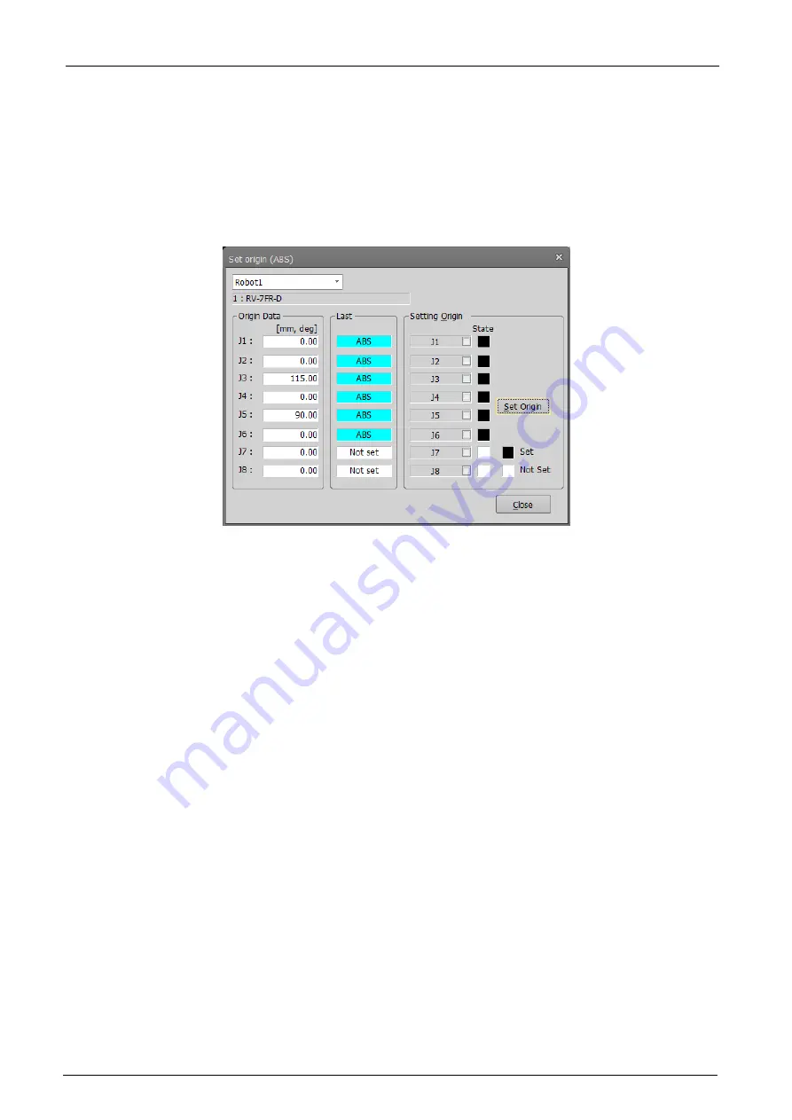
This uses the robot's ABS origin position robot to set the robot origin.
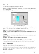
Click the origin data screen [ABS] button to display the screen.
After moving the robot to the ABS origin position, select the axis to set the origin for with the checkbox, and then
click the [Set origin] button.
"Last" displays the origin setting technique used the previous time. This is sometimes not displayed for some
robot controller software versions.
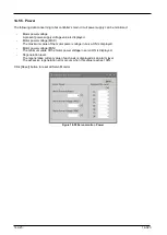
Figure 15-6 Origin Setting (ABS) Screen
In this method, we use the ABS mark to set the origin. The ABS mark is a triangular mark attached to each axis or
Scribe line. The robot stores the position within one revolution of the encoder,you can set the exact origin by
matching the ABS mark within 1mm of the deviation. Please follow the procedure below.
<Common to RH / RV series>
1) Move with jog so that the deviation amount of ABS mark is within 1 mm.
2) Select the axis form the above screen and click the [Set Origin] button.( Can be set simultaneously on
multiple axes)
3) 1 - 2 correspond to the J1 - J2 axes of the RH series, and the J1 - J4 axes of the RV series.
< RH series >
4) Set the origin of the J3 and J4 axes at the same time. Release the brake of J3 and contacted with the + side
of the machine stopper. In this state, align the J4 axis with the mark.
5) End brake release.
6) Select the J3 and J4 axes from above screen and click the [Set Origin] button.
< RV series >
6) Set the origin of the J5 and J6 axes at the same time. J5, J6 axis simultaneously execute 1 - 2.
* The position of ABS mark will vary depending on the model. Please refer to [Robot Setup to Maintenance].
15.1.5. User Origin Method
This uses the robot user origin to set the robot origin.
Click the origin data screen [User origin method] button to display the screen.
After moving the robot to the user origin position, use the checkbox to select the axis to set the origin of, and then
click the [Set origin] button.
"Last" displays the origin setting technique used the previous time. For some robot controller software versions,
this is sometimes not displayed.
Summary of Contents for 3F-14C-WINE
Page 84: ...8 84 8 84 Figure 8 21 Parameter transfer procedure 1 2 2 ...
Page 393: ...18 393 18 393 Figure 18 1 Starting the Oscillograph ...
Page 413: ...18 413 18 413 Figure 18 24 Output to Robot program Selection ...
Page 464: ...18 464 18 464 Figure 18 72 Starting the Tool automatic calculation ...
Page 545: ...21 545 21 545 Figure 21 55 Hide display of user mechanism ...
Page 624: ...24 624 24 624 Figure 24 4 Document output example ...

