Maintenance
43
2.
Boundary adjustment
The boundaries between the LED modules can be
adjusted when necessary while LED unit mounting
(p. 14) or after LED module replacement (p. 39).
Adjust them combining with edge brightness
compensation (p. 26).
1.
Follow the boundary check (p. 18) procedure to
check if the boundary adjustment is needed.
2.
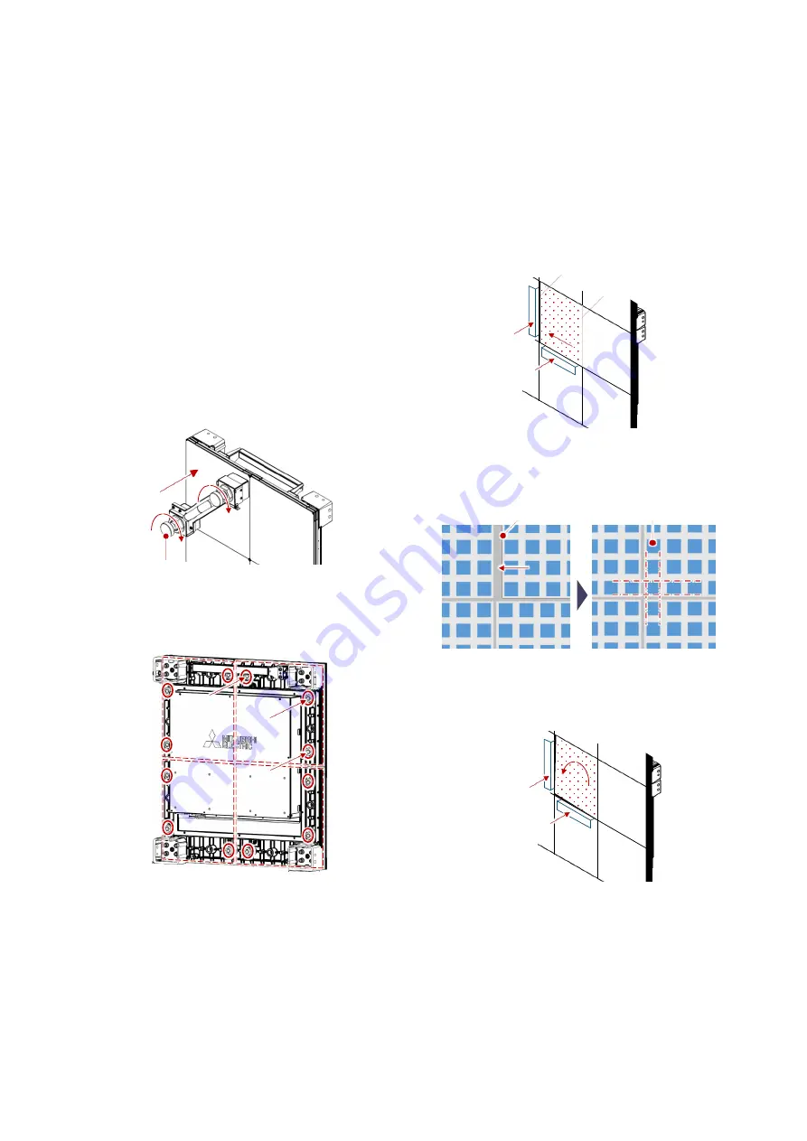
Loosen the fixing screws behind the LED
module.
For the front maintenance models, attach the
detachment tool on the LED module to be
adjusted, and rotate the outer knobs anti-
clockwise roughly one turn. The module will be
able to move around.
For the rear maintenance models, loosen 3
fixing screws located in the back side of the
module.
3.
Insert the spacers into wider boundary and
underneath the module.
The standard gap width between the LED
modules are 0.125 mm for 12NP and 0.19 mm
for 15NP. Spacers with similar thickness are
recommended for fine adjustment.
4.
Shift the module toward the spacers to be the
optimum position as the LED chips are aligned
horizontally and vertically.
Likewise, when the module has been tilted,
slightly rotate the module toward the spacers
to be the optimum position.
5.
Fix the LED module according to the LED
module replacement procedure.
6.
Follow the boundary check (p. 18) procedure
again to check if further adjustment is needed.
Outer knobs
LED chips
LED module
Spacers
Wider boundary
Narrower boundary
Spacers
Summary of Contents for 12NP180 Series
Page 50: ......


