background image

TA7102 Hardware Installation 


13 

153/1531-ANF 901 14 B 2017-03-08 


3


INSTALLATION 

This chapter describes the installation of the TA7102. 

3.1 

PLANNING THE INSTALLATION 

Before installing the TA7102, you should complete the following tasks: 


Create a 

network diagram (see section “Network Diagram”). 


Gather IP-

related information (see section “IP-Related Information” for more information). 


Install the hardware and software needed to configure the TA7102 (see section

“Network Information”). 


Installation Checklist 

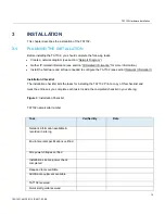
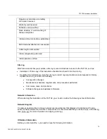
The installation checklist lists the tasks for installing the TA7102. Print a copy of this checklist and  

mark the entries as you complete each task. Include the completed checklist in your site log. 


Figure 3

: Installation Checklist 


TA7102 name/serial number 


Task


Verified By


Date


Network information available & 
recorded in site log 


Environmental specifications verified 


Site power voltages verified 


Installation site pre-power check 
completed 


Required tools available 


Additional equipment available 


TA7102 received 


Quick start guide received 


Summary of Contents for TA7102

Page 1: ...Mitel TA7102 INSTALLATION GUIDE...

Page 2: ...be issued to incorporate such changes No part of this document can be reproduced or transmitted in any form or by any means electronic or mechanical for any purpose without written permission from Mit...

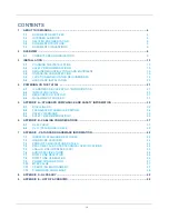
Page 3: ...N 27 4 4 MANAGEMENT CHOICES 31 5 APPENDIX A STANDARD COMPLIANCE AND SAFETY INFORMATION 32 5 1 DISCLAIMERS 32 5 2 TRANSLATED WARNING DEFINITION 34 5 3 SAFETY WARNINGS 35 5 4 SAFETY RECOMMENDATIONS 36 6...

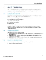
Page 4: ...are installation instructions Installation scenarios examples LED indications Cabling and pin out data Please refer to the Dgw v2 0 Software Configuration Guide for software configuration information...

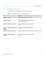
Page 5: ...102 Chapter 2 Installation Contains instructions for installing the TA7102 and connecting the cables Chapter 3 Powering on the TA7102 Leads you through the basic steps to start the TA7102 Appendix A S...

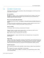
Page 6: ...you will encounter in this manual Caution Indicates a potentially hazardous situation which if not avoided may result in minor or moderate injury and or damage to the equipment or property Note Indica...

Page 7: ...TA7102 Hardware Installation 7 153 1531 ANF 901 14 B 2017 03 08 For more information on and a list of RFCs and Internet Drafts refer to the IETF web site at http www ietf org...

Page 8: ...rs switches enabling to establish two connections between conventional analog telephones or Group 3 fax machines and either a WAN a LAN or a personal computer It can be used to provide connectivity to...

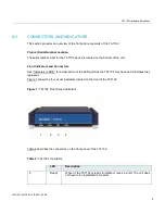
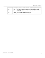
Page 9: ...nt Indicators and Connectors See Indicators LEDs for a description of the LED patterns the TA7102 may have and the states they represent Figure 1 shows the four visual indicators located on the front...

Page 10: ...ion 153 1531 ANF 901 14 B 2017 03 08 10 2 In Use When lit at least one of the FXS lines is in use 3 ETH Provides the state of the network connected to the WAN and LAN connectors 4 Power When lit power...

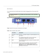
Page 11: ...om left to right Table 3 Rear Connections of the TA7102 Connection Description 1 Phone Fax 1 Phone Fax 2 Two RJ 11 connectors to attach a conventional telephone or G3 fax machine 2 LAN A 10 100 BaseT...

Page 12: ...TA7102 Hardware Installation 12 153 1531 ANF 901 14 B 2017 03 08 5 Power connector External 12 Vdc power supply...

Page 13: ...o configure the TA7102 see section Network Information Installation Checklist The installation checklist lists the tasks for installing the TA7102 Print a copy of this checklist and mark the entries a...

Page 14: ...log Upgrades and maintenance Use the site log to record ongoing maintenance and expansion history Update the site log to reflect the following Configuration changes Maintenance schedules requirements...

Page 15: ...nnectors regardless of whether power to the device is OFF or ON Use caution when working near these connectors to avoid electric shock When detaching cables detach the end away from the TA7102 first G...

Page 16: ...ains the following items 1 x TA7102 unit 1 x power cord for the country in which you are using the TA7102 1 x universal power supply 1 x 10 100 BaseT Ethernet RJ 45 cable 1 x Printed Flyer You may als...

Page 17: ...hrough the vents of the unit The unit requires a minimum of 25 mm 1 in clearance The operating temperature is between 0 C and 40 C The humidity is not over 85 and is non condensing Wiring Requirements...

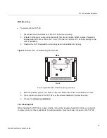
Page 18: ...st the wall or plywood as illustrated in Figure 4 Figure 4 Bottom View Wall Mounting Screw Holes Rear Screw holes Front You can position the TA7102 any way you want 4 Mark the position of the screw ho...

Page 19: ...ght be harmful to the unit If this occurs allow the unit to acclimatize for an hour before powering it on Cleaning To clean the TA7102 wipe with a soft dry cloth Do not use volatile liquids such as ga...

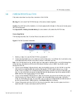
Page 20: ...ith a conventional telephone or fax machine Connections to FXS ports of third party devices such as a PBX Key System could damage the TA7102 3 Connect a 10 100 BaseT Ethernet RJ 45 cable into the WAN...

Page 21: ...the same subnet via a DHCP server or PPP peer you will not be able to contact the unit via the WAN You must be careful that a dynamic IP address does not overlap a static IP subnet that is already co...

Page 22: ...for more details Initial Provisioning Sequence When starting the TA7102 for the first time it needs to be configured before it can support calls This process is known as provisioning This sequence as...

Page 23: ...e for more details IPv6 Link Local Address Configuration If there is no DHCPv6 server or IPv6 router in your network you can use the link local address to contact the unit Note that the TA7102 IPv6 in...

Page 24: ...ones connected to the TA7102 2 Dial one of the digits sequence on the keypad Table 4 Vocal Unit Information Digits to Dial Information Vocally Sent by the TA7102 0 Current IP address of the TA7102 sta...

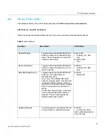
Page 25: ...ending Triggered when the RESET DEFAULT button is pressed at start time or for at least 7 seconds All LEDs blinking 1Hz 50 duty DefaultSettingsPendin g Triggered when the RESET DEFAULT button is not r...

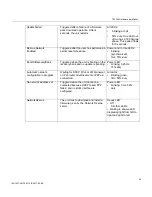
Page 26: ...ggered when the unit is booting on the recovery bank and no update is pending Power LED blinking 0 25Hz 75 duty Automatic network configuration in progress Waiting for DHCP IPv4 or IPv6 answer or IPv6...

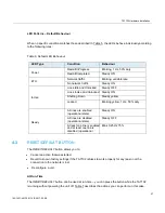
Page 27: ...Down Steady yellow Locked Blinking yellow 1 Hz 50 duty Ready All lines are enabled operational state Steady ON All lines are disabled operational state Steady OFF At least one line is enabled and at...

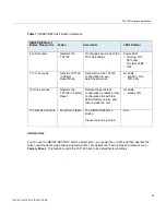
Page 28: ...All LEDs blinking 1Hz 50 duty 12 to 16 seconds Restarts the TA7102 in Factory Reset Deletes the persistent configuration creates a new configuration file with the default factory values and then rest...

Page 29: ...ervice Resets the enableSnmpV1 enableSnmpV2 enableSnmpV3 and snmpPort values to their default values WEB service Resets the serverPort to its default value To trigger the Partial Reset Insert a small...

Page 30: ...pack download configuration files The SNMP configuration including the SNMPv3 passwords and users The PPPoE configuration including the PPP user names and passwords The Factory reset creates a new con...

Page 31: ...t alters any persistent configuration data of the TA7102 4 4 MANAGEMENT CHOICES Congratulations for properly installing the TA7102 You can now configure the software parameters of the unit The TA7102...

Page 32: ...ce will not occur in a particular installation If this equipment does cause harmful interference to radio or television reception which can be determined by turning the equipment off and on the user i...

Page 33: ...TA7102 Hardware Installation 153 1531 ANF 901 14 B 2017 03 08 33 DECLARATION OF CONFORMITY Please contact your Mitel office or Sales partner...

Page 34: ...in einer Situation die zu einer K rperverletzung f hren k nnte Bevor Sie mit der Arbeit an irgendeinem Ger t beginnen seien Sie sich der mit elektrischen Stromkreisen verbundenen Gefahren und der Sta...

Page 35: ...sposal Warning Warning Ultimate disposal of this product should be handled according to all national laws and regulations No 26 AWG Warning Warning To reduce the risk of fire use only No 26 AWG or lar...

Page 36: ...ur liquids into it Do not perform any action that creates a potential hazard to people or makes the equipment unsafe Caution When using this equipment basic safety precautions should always be followe...

Page 37: ...minimum of 26 AWG wire size It is possible to use either a crossover or straight Ethernet cable to connect in the Ethernet connectors These connectors perform automatic MDI MDIX detection meaning tha...

Page 38: ...6 Receive Orange with white stripe or solid orange Green with white stripe or solid green 7 N A White with brown stripe or solid brown White with brown stripe or solid brown 8 N A Brown with white st...

Page 39: ...d 8 not connected Crossover Cable A RJ 45 crossover cable is used when only two systems are to be connected to each other peer to peer at the Ethernet Cards by crossing over reversing their respective...

Page 40: ...tor must be attached to both ends of the cable Each wire pair must be attached to the RJ 11 connectors in a specific orientation The following figure illustrates how the pins on the RJ 11 connector ar...

Page 41: ...TA7102 Hardware Installation 41 153 1531 ANF 901 14 B 2017 03 08 EIA TIA IS 968 CS 03 Issue 8 Part III requirements Warning The RJ 11 cable should comply with UL 1863 and CSA C22 2 No 233 standards...

Page 42: ...ill eventually be implemented at a later date Because of this specific design characteristic the TA7102 can be integrated with existing telephone fax and data equipment such as PCs and routers Table 1...

Page 43: ...TA7102 Hardware Installation 43 153 1531 ANF 901 14 B 2017 03 08 QoS ToS DiffServ 802 1p 802 1Q...

Page 44: ...communications using any vocoders DSP based DTMF detection and generation DSP based fax data relay Embedded operating system with 32 bit real time multitasking Kernel Embedded IPv4 TCP IP stack with c...

Page 45: ...e Loop current detection and hook flash detection capable Generation of Selective Ring Table 15 Analog Line Interface Parameter Description Trunk Type Loop Start capable of Wink and Immediate signaliz...

Page 46: ...ble 7 7 DTMF TONE DETECTION Table 16 DTMF Tone Detection Parameter Description 16 Digit DTMF Decoding 0 to 9 A B C D Permitted Amplitude Tilt High frequency can be 4 dB to 8 dB relative to low frequen...

Page 47: ...s off hook 475 5 7 TBD TBD 12Vdc All ports ringing into 4REN 450 5 4 TBD TBD 7 10 MTBF VALUE The Mean Time Before Failure MTBF value of the TA7102 models is 750 000 hours These values are at 25 degree...

Page 48: ...Installation 48 153 1531 ANF 901 14 B 2017 03 08 7 12 DIMENSIONS AND WEIGHT Table 20 Dimensions and Weight Parameter Description Dimensions 3 1 cm x 12 7 cm x 9 9 cm 1 2 in x 5 in x 3 9 in approx Weig...

Page 49: ...responds to a different pair of frequencies Each pair of frequencies corresponds to one of the ten decimal digits or to the symbol or the being reserved for special purposes Dynamic Host Configuration...

Page 50: ...ommunications between onsite telephones and exterior communications networks Protocol A formal set of rules developed by international standards bodies LAN equipment vendors or groups governing the fo...

Page 51: ...packets for local destinations from packets for remote destinations in TCP IP networks Transmission Control Protocol Internet Protocol TCP IP The basic communication language or protocol of the Inter...

Page 52: ...Internet Protocol LAN Local Area Network ma milliampere MAC Media Access Control MDI Media Dependent Interface MDIX Media Dependent Interface Crossover PBX Private Branch eXchange PSTN Public Switche...

Page 53: ...TA7102 Hardware Installation 153 1531 ANF 901 14 B 2017 03 08 53...

Reviews: