background image

I

NSTALLING

 B

OARDS


AND

 C

ABLING

25

21/1531-ASP11301 Uen B3 2016-02-17

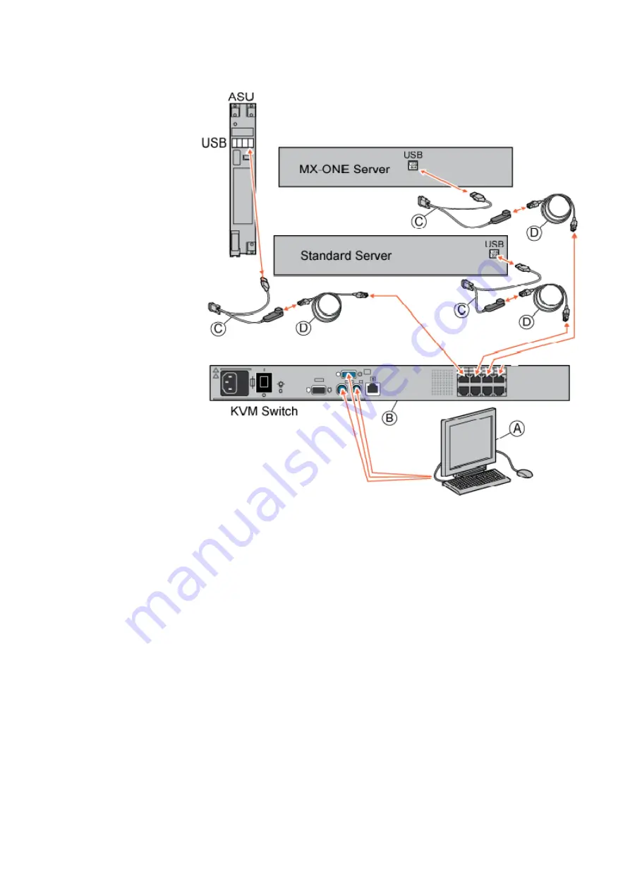
Figure 17:  Connecting Keyboard and Monitor

3.5 

EXTENSION AND TRUNK LINE CABLE STRUCTURE

The twisted pair cable used for Extension and trunk lines in the MX-ONE is delivered 
with 32 pairs. The cable is structured either with 8 pairs in 4 bundles, 2 blue and 2 
orange bundles, or, with 16 pairs in 2 bundles, 1 blue and 1 orange. Each bundle is 
kept together with a bundle thread, see Figure 18:  Cable Structure on page 26

Summary of Contents for MX-ONE

Page 1: ...INSTALLATION INSTRUCTION INSTALLATION INSTRUCTION Installing Boards and Cabling Catarina Sten csten Göran Lannergren glannergren Globen Mitel R D MX ONE CMG ...

Page 2: ...aries Mitel and its affiliates and subsidiaries assume no responsibility for any errors or omissions in this document Revisions of this document or new editions of it may be issued to incorporate such changes No part of this document can be reproduced or transmitted in any form or by any means electronic or mechanical for any purpose without written permission from Mitel Networks Corporation Trade...

Page 3: ... is aimed for customers doing new installation For other parts of the Installation see Installation preparation and Earthing 19 1531 ASP11301 Installation Chassis in a Cabinet 20 1531 ASP11301 1 2 TARGET GROUP The target group for this document is personnel involved in installing the MX ONE 1 3 PREREQUISITES This section lists requirements that must be fulfilled before the installation starts 1 3 ...

Page 4: ...ow ASU II ROF 137 6307 4 40mm Mitel Server Unit 16GB For more information see item below DC DC ROF 137 6303 1 40mm Power unit for 7U chassis ELU26 ROF 137 5321 12 20mm 8 ISDN S digital extensions ELU31 ROF 137 5412 4 20mm 32 DECT extensions ELU33 ROF 137 5062 1 20mm 32 Digital extensions ELU34 ROF 137 5064 x 20mm 32 Analog extensions with message waiting FTU2 ROF 137 5415 11 20mm 8 Failure Transfe...

Page 5: ... MGU AND MGU2 The MGU board has a 40mm front when used in MX ONE Classic MX ONE Lite and in MX ONE 1U chassis The MGU2 board has a 20mm front and can be used in any chassis Close to the LED there is a hole for performing reset For more info see description Media Gateway Unit MGU 1 1551 ANF90136 2 3 EMPTY BOARD POSITIONS If any empty positions are left in a chassis after mounting all boards these e...

Page 6: ...OARD FRONTS This section describes the connectors and LEDs on the boards The indication of board status with dual color LED is Steady RED The board is in passive state Flashing RED Error state Alternating RED GREEN The board is starting up or is blocked Steady GREEN The board is active Flashing GREEN The board is active and is signaling Note DC DC MGU TLU77 and ASU boards deviate from above See th...

Page 7: ...INSTALLING BOARDS AND CABLING 7 21 1531 ASP11301 Uen B3 2016 02 17 Figure 2 TLU77 TMU TLU76 ELU33 and ELU34 Board Fronts ...

Page 8: ...NG BOARDS Figure 3 ASU Front Connectors The SATA disks are located behind a cover Two disks are used for RAID 1 M0001172A ASU E SATA 0 SATA 1 1 0 Connector no 1 Connector no 2 LED Green Connector no 3 15 pole female D sub 2 RJ 45 ports 4 USB Ports ...

Page 9: ...INSTALLING BOARDS AND CABLING 9 21 1531 ASP11301 Uen B3 2016 02 17 Figure 4 DC DC Front Connectors and LEDs DC DC FAN UNIT ALARM IN 48V INPUT ...

Page 10: ...21 1531 ASP11301 Uen B3 2016 02 17 10 INSTALLING BOARDS Figure 5 ALU2 ELU31 TLU79 TLU80 and TLU83 Fronts Note ELU26 has the same front view as TLU79 ...

Page 11: ...INSTALLING BOARDS AND CABLING 11 21 1531 ASP11301 Uen B3 2016 02 17 Figure 6 TLU77 Front Connectors and LEDs ...

Page 12: ...MGU2 with 20mm front Status LED Green Red Green flashing Red flashing See the MGU description for details E1 T1 USB MGU RESET button Status LED Green Red Green flashing Red flashing LAN connections USB connection E1 T1 connections Reset LAN1 LAN0 1 2 3 4 behind front Key hole See the MGU2 description for details ...

Page 13: ...ry std 61L00006AAA A to AC DC included in cable kit for 1U power 87L00036AAA A For 2U the cable is included in the unit Battery UK TSR 903 0113 1 to AC DC only for UK Battery TFL281325 4000 Between batteries for parallel connection DC DC TSR 903 021 5000 12M to 1U or 2U AC DC TSR 490 0116 5000 12M to 1U or 2U AC DC for the UK ELU26 TSR 491 414 32M to MDF ELU31 ELU33 ELU34 TSR 910 1054 16M 32M to M...

Page 14: ...ns are marked in numerical order starting from 1 for the lowest connector position 2 for the position above it and so on see Figure 9 Connectors positioning on page 15 MX ONE 1U chassis 87L00032xAA A TSR9020279 2000 to AC DC 48V Network TSR 482 0211 20M LAN 100KBit RJ45 RJ45 straight L 20 meters 61L00002BAA A LAN 1GBit RJ45 RJ45 straight L 20 meters Power to Fan TSR 903 021 5000 12M TSR 490 0116 5...

Page 15: ...INSTALLING BOARDS AND CABLING 15 21 1531 ASP11301 Uen B3 2016 02 17 Figure 9 Connectors positioning ...

Page 16: ...MX ONE Service Node has a label set with labels that are used to mark the cables in the MX ONE See Table 4 on page 16 Table 4 3 2 3 LABELING OF CABLES Note To mark source and destination for the cable always put a label on each cable end Cables are marked with labels in both ends The labels contain the following informa tion Cable source Cable destination Product Number Server Number Product Numbe...

Page 17: ...ling Cables 3 2 4 LABELING OF INTERNAL CABLES The internal cables connected to fixed positions in the exchange are already labeled at delivery The label indicates the position of the cable s own connector as well as that of the other end For example GW1 81 0 21 4 means that for Gateway 1 cable 81 is to be placed on the left side of MGU 0 left 1 right board position 21 01 05 09 77 and at connector ...

Page 18: ...training and experience necessary to be aware of hazards to which they can be exposed The battery fuse circuit breaker is located in the power supply unit It means that the conductor connected to the negative pole of the battery and to the battery fuse circuit breaker is an unfused battery conductor It is extremely hazardous to work with unfused battery conductors Note Before battery conductors ar...

Page 19: ...A10911 the 2U AC DC see document BCG 00075 for User manual and 1 1531 BZA10911 for Quick Install Guide 4 Connect the cable lug M of the black cable to the minus pole D of the leftmost battery block see Figure 13 Connecting the Batteries on page 19 5 Fasten the screw B to secure the cable lug and press down the cover I on the black minus pole D 6 Connect the black negative 48V DC supply cable M to ...

Page 20: ...rby cables to each others and to any cable cloth or frame using fastener straps included in the 25 BYB 501 1 This to relieve the force on the connections Table 5 Set of Cable holders Cable tie Note Do not cut the cables The shortest length of the cables from the AC DC unit to the DC DC board must be 5 meters Note For the UK market the cable TSR 490 0116 is used Also note that the blue cable is pos...

Page 21: ...c with 2U Power Unit on page 48 Note If only one Power cable is connected to the Fan Unit the alarm on the Fan will be activated This is not possible to re configure To avoid the alarm in the Fan feed the unit with 2 Power cables Figure 14 Cabling to the Fan Unit BFD50908 4 3 3 5 CONNECTING POWER TO 1U CHASSIS 87L00032XAA A Connect the 48V DC power to the 1U chassis using cable TSR9020279 2000 The...

Page 22: ...021 xxx The connector on the DC DC board is located on the front 3 4 CONNECTING CABLES Some cables are pre connected at delivery depending on equipment configuration ordered Use the figure and the table below to connect cables or to verify that the cables are correctly connected For cable connections to board positions see Figure 15 Cable Connections Configure Example on page 22 and Figure 16 MX O...

Page 23: ...D CABLING 23 21 1531 ASP11301 Uen B3 2016 02 17 Figure 16 MX ONE Lite cabling example The MGU is connected to a server via the corporate LAN i e a Switch This is also valid when multiple gateways are connected to a server ...

Page 24: ...e Figure 17 Connecting Keyboard and Monitor on page 25 Note A Keyboard Video Mouse KVM switch expansion KDU 137 346 must be used if more than eight servers are to be connected to the keyboard and monitor Pos Title Function Product Number A MX ONETM Keyboard and Monitor Package XX KDT 252 01 1 B Rack Mount Server KVM Switch 8 ports KDU 137 390 Rack Mount Server KVM Switch Expansion 8 ports KDU 137 ...

Page 25: ...CABLE STRUCTURE The twisted pair cable used for Extension and trunk lines in the MX ONE is delivered with 32 pairs The cable is structured either with 8 pairs in 4 bundles 2 blue and 2 orange bundles or with 16 pairs in 2 bundles 1 blue and 1 orange Each bundle is kept together with a bundle thread see Figure 18 Cable Structure on page 26 ...

Page 26: ... tables specify the color coding of the 32 pair cable used for ELU33 ELU34 and other boards and the connection cable used for TLU76 TLU77 and ELU26 TLU79 Use the tables below to connect extension and trunk cables to the MDF Note that the screen also shall be grounded on the MDF side due to the demand of Multi point earthing See document 19 1531 ASP11301 Figure 19 32 pair cable for ELU33 ELU34 ELU3...

Page 27: ...ivated as the first individual and removed as the last individual or else the communications with the board will fail Table 7 Color Coding in 32 Pair Cable for ELU33 ELU34 and ELU31 Front LED Front connector A 1 2 3 4 5 6 1 7 8 9 10 11 12 2 13 14 15 16 17 18 3 B C D Pair Core Color Bundle Connector Pair Core Color Bundle Connector 1 a White D18 21 a White D9 b Blue C18 b Blue C9 ...

Page 28: ... Red D16 26 a Red A6 b Blue C16 b Blue B6 7 a Red A15 27 a Red D6 b Orange B15 b Orange C6 8 a Red D15 28 a Red A5 b Green C15 b Green B5 9 a Red A14 29 a Red D5 b Brown B14 b Brown C5 11 a Black D14 31 a Black A4 b Blue C14 b Blue B4 12 a Black D13 32 a Black D4 b Orange C13 b Orange C4 13 a Black D12 33 a Black A3 b Green C12 b Green B3 14 a Black A11 34 a Black D3 b Brown Blue B11 b Brown Orang...

Page 29: ...ter for blocking ind 0 B16 3B4 BLK0 BLK receiver for blocking ind 0 A16 3A4 R00 Return wire ind 0 C9 2C3 R10 Return wire ind 0 D9 2D3 R20 Return wire ind 0 B8 2B2 R30 Return wire ind 0 A8 2A2 M1 M lead transmitter ind 1 C16 3C4 E1 E lead receiver ind 1 D16 3D4 A1 A lead transmitter for blocking ind 1 B14 3B2 BLK1 BLK receiver for blocking ind 1 A14 3A2 R01 Return wire ind 1 C8 2C2 R11 Return wire ...

Page 30: ... TLU80 and TLU83 TSR 910 1054 16M or 32M on page 26 Table 9 RFP front connector configuration X6 R03 Return wire ind 3 B5 1B5 R13 Return wire ind 3 A5 1A5 R23 Return wire ind 3 C5 1C5 R33 Return wire ind 3 D5 1D5 Signal Description Connector row Connector row A B C D 1 Not used 2 Not used 3 Not used 4 Not used 5 EPB6 red EPA6 green EPB7 brown EPA7 red 6 EPB4 red EPA4 blue EPB5 orange EPA5 red ...

Page 31: ...EPA0 white 10 LB13 yellow LA13 orange LB14 green LA14 yellow 11 LB11 black LA11 brown LB12 blue LA12 yellow 12 Not used LB10 green LA10 black 13 Not used LB9 orange LA9 black 14 LB7 red LA7 brown LB8 blue LA8 black 15 LB5 red LA5 orange LB6 green LA6 red 16 LB3 white LA3 brown LB4 blue LA4 red 17 LB1 white LA1 orange LB2 green LA2 white 18 Not used LB0 blue LA0 white A B C D 1 Ring TX comm Bus com...

Page 32: ...rows 7 to 14 are used The remaining 14 wire pairs are not connected and marked NC See Table 12 Color Coding in 32 Pair Cable for TLU83 TSR 910 1054 16M or 32M on page 32 Table 12 Color Coding in 32 Pair Cable for TLU83 TSR 910 1054 16M or 32M Pair TL Ind Core Color Bundle Connector Pair TL Ind Core Color Bundle Connector 1 NC a White D18 21 8 a White D9 b Blue C18 b Blue C9 2 NC a White A17 22 9 a...

Page 33: ...31 NC a Black A4 b Blue C14 b Blue B4 12 1 a Black D13 32 NC a Black D4 b Orange C13 b Orange C4 13 2 a Black D12 33 GND a Black A3 b Green C12 b Green B3 14 3 a Black A11 34 GND a Black D3 b Brown Blue B11 b Brown Orange C3 16 4 a Yellow D11 36 GND a Yellow A2 b Blue C11 b Blue B2 17 5 a Yellow A10 37 GND a Yellow D2 b Orange B10 b Orange C2 18 6 a Yellow D10 38 GND a Yellow A1 b Green C10 b Gree...

Page 34: ...Color Pinn No Description Pair Core Color Connector Description 1 A White C6 Individual 0 TX TX B Blue D6 2 A White A6 Individual 1 TX TX B Orange B6 3 A White C5 Individual 0 RX RX B Green D5 4 A White A5 Individual 1 RX RX B Brown B5 6 A Red C4 Individual 2 TX TX B Blue D4 7 A Red A4 Individual 3 TX TX B Orange B4 8 A Red D3 Individual 2 RX RX B Green C3 9 A Red B3 Individual 3 RX RX B Brown A3 ...

Page 35: ... m short passive bus with 8 terminals ELU31 For information see Installation Instructions for CORDLESS PHONES ELU33 600 m if using a twisted pair cable with wire diameter 0 4 mm 1000 m if using a twisted pair cable with wire diameter 0 5 mm point to point with one terminal ELU34 6000 m if using a twisted pair cable with wire diameter 0 4 mm 9000 m if using a twisted pair cable with wire diameter 0...

Page 36: ...rd when the board is removed from the subrack with the power still on a so called hotswap Do not touch the board component or solder points for a few minutes after the removal To reduce the high voltage to a safe level leave the board un plugged in the subrack for at least 15 seconds 4 4 DIGITAL EXTENSIONS As an example digital system telephones may have the type designations DBC 2XX connected to ...

Page 37: ...ngths for DTS see documentation in Mitel TSW or older MX ONE version 4 4 2 ISDN EXTENSIONS WITH ELU26 The ISDN terminals are connected to the ELU26 board in the PBX through the MDF Figure 25 Example with an ISDN terminal 4 wire connection 4 5 CORDLESS EXTENSIONS ELU31 To the ELU31 4 radio base stations RFPs are to be connected see Figure 26 ELU31 4 MDF RFP on page 37 For more information see Insta...

Page 38: ...g TLU boards Figure 28 TLU8x MDF example 4 7 DIGITAL EXTERNAL LINES Note If the ISDN T1 interface shall be connected outside the premises it is mandatory to connect the T1 lines via a Network Terminal 1 NT1 Channel Service Unit CSU or National Certified Terminal Equipment NCTE interface This is essential in order to comply with US and CA regulatory safety requirements in force TLU 8x TLU8x ...

Page 39: ...m pair cable 4 7 2 ISDN 4 7 2 1 ISDN PRI with TLU76 11 Color coding for TLU76 with cable TSR4820211 xxxx see item 3 5 3 TLU76 and TLU77 cable structure on page 33 Figure 30 Digital external lines 120 ohm pair cable TLU76 11 14 4 7 2 2 Digital external lines with TLU79 and an NT1 box Network Terminal box Color coding for TLU79 with cable TSR491414 xxx see item 3 5 4 ELU26 and TLU79 cable structure ...

Page 40: ...preferably be performed in the MDF 4 7 2 3 Digital external line with TLU79 as a tie line Color coding for TLU79 with cable TSR491414 xxx see item 3 5 4 ELU26 and TLU79 cable structure on page 34 Figure 32 Connecting TLU79 to TLU79 through MDF 8 pairs 4 8 THROUGH CONNECTION ON POWER FAILURE OR PROCESSOR MALFUNCTION If the exchange is equipped with an FTU2 board one to 32 extensions 8 per FTU2 boar...

Page 41: ...tary dial telephone or a telephone for 10 pps pulse generator The connection to the public exchange must be of analog type Figure 33 Through Connection on Power Failure or Processor Malfunction 4 9 CALL METERING 4 9 1 CALL METERING TLU83 2 The TLU83 2 is needed as this board contains the call metering hardware The metering frequency of 12 kHz or 16 kHz is set when the board is activated 4 10 PRIVA...

Page 42: ... boards the simplest way is to use the alarm input on the DC DC board and configure the MGU boards to monitor Alarm A and or Alarm B input When many external alarm shall be monitored or when system is not equipped with MGU boards an ALU2 board can be used The ALU2 board can receive up to eight different alarm signals and send out up to seven control signals See Figure 34 ALU2 MDF connections on pa...

Page 43: ...ector on the Fan and connect the other end to the MDF see Figure 35 MDF Alarms for the Fan Unit BFD 509 08 4 on page 44 Connect the Plug SXK 106 2097 1 in the second D sub connector on the Fan to receive a signal loop 8 Alarm inputs MDF Pair 1 2 3 4 6 7 8 9 AL7 AL6 AL5 AL4 AL0 AL1 AL2 AL3 TSR 491 0306 ALU2 Pair 1 2 3 4 6 7 8 9 AL23 AL22 AL21 AL20 AL16 AL17 AL18 AL19 8 Alarm outputs TSR 491 0306 X1...

Page 44: ...lost of one of the 48V feeding Table 16 Fan Unit Alarms 5 2 MIVOICE MX ONE LITE 3U UNIT EXTERNAL ALARM The Alarm Input which is located on the rear side of the unit has two pins 1 and 3 which can be detected as alarms when either of them is closed to ground To reach the MDF a b a b a b a b a b a b a b a b ALU2 2 x TSR 491 0306 20M inputs FAN unit BFD 509 08 4 Violet FAN alarm Turquoise GND TSR9020...

Page 45: ...are internally tied to 48 V through serial resistors and the board can therefore detect loop or closing to 0 V The resistance from the source to the ALU2 input should be maximum 20 kohm 5 3 1 FOR BZA 109 11 2U POWER UNIT For information see the documentation delivered with the product These documents are also stored in the Alex data base in parallel with this document See document BCG 00075 for Us...

Page 46: ...21 1531 ASP11301 Uen B3 2016 02 17 46 ALARMS Figure 36 Top and front view of BZA 109 11 Figure 37 Rear view of BZA 109 11 ...

Page 47: ... on page 46 Note The picture shows the 2U Power Unit but the 1U Power unit has the same connectors but in another position The communication with the AC DC unit can also be done via the com module The modules have a RJ45 connector to communicate with the LAN 5 4 AC DC ALARM THROUGH MGU 5 4 1 MIVOICE MX ONE LITE 87L00039XAA A WITH 1U POWER UNIT Figure 38 MGU Power Alarm Detection in MX ONE Lite The...

Page 48: ...s used The Supervision Extension port must be terminated with alarm plug SXK 106 2097 1 on the FAN_2 unit Figure 39 MGU Power and Fan alarm in Classic subracks The following connections are used 1 Power cable TSR 903 021 5000 free end on power unit side 2 Alarm cable TSR 902 0277 2000 free end on power unit side 3 FAN_2 Alarm cable TSR 902 0274 2200 free end on power unit side 4 Alarm plug SXK 106...

Page 49: ...ING BOARDS AND CABLING 49 21 1531 ASP11301 Uen B3 2016 02 17 Optional cables and plug Only needed if alarm handling is required For details about the 2U power connection see doc BCG 00075 Supplier User Manual ...

Reviews: