


Documentation is subject to change without notice. See
http://www.mircom.com/tx3 for the latest version of this document.
Mircom technical support: 1-888-647-2665
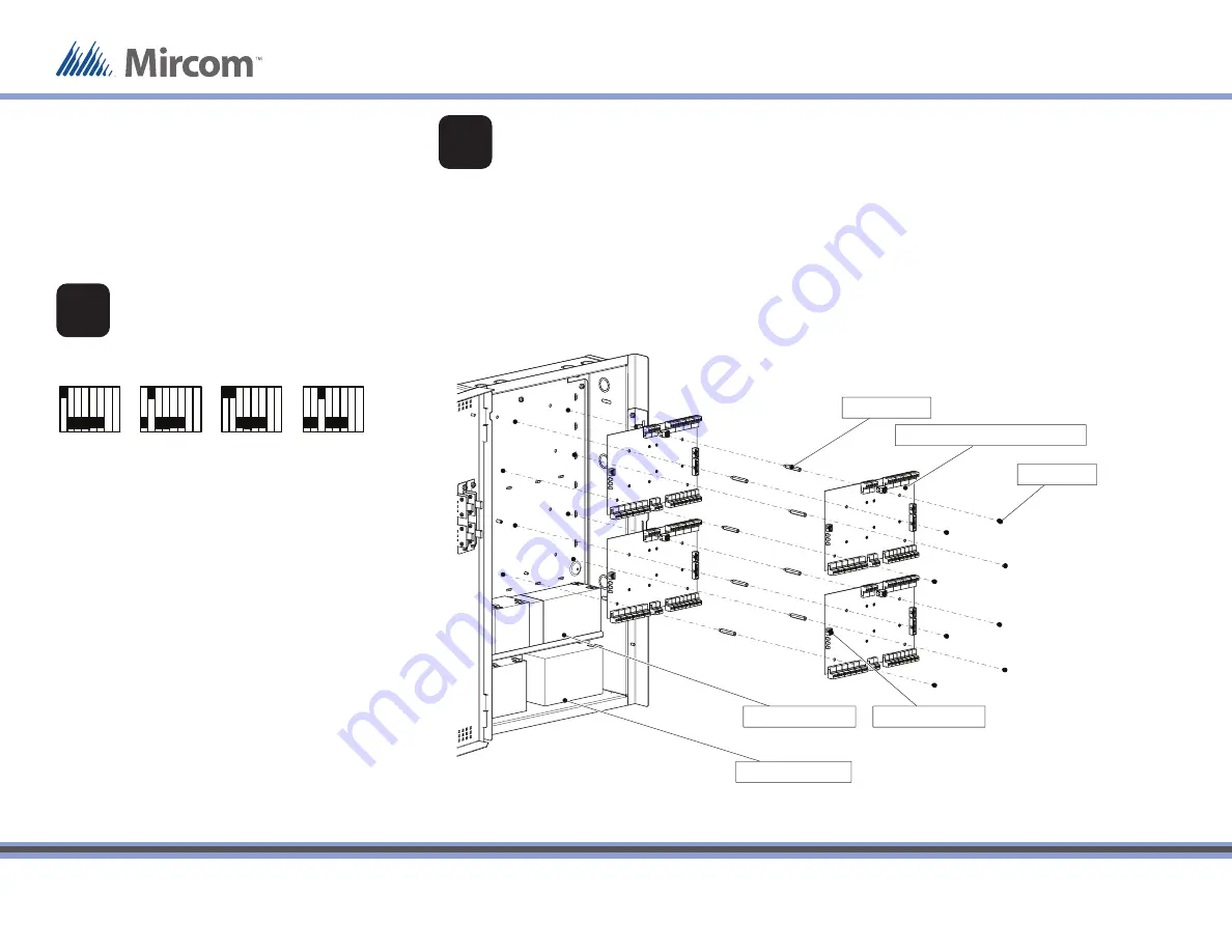
TX3-BBCX-4W Assembly
Lower battery shelf
Upper battery shelf
Standoffs (x8)
Card Access Controller (MD-1093)
P7 LED display port
Screws (x8)
MOUNT AND WIRE THE CARD ACCESS
CONTROLLERS (CONTROL BOARDS)
•
Mount each control board so that the mounting
posts align and the P7 LED display port is on the
left. (The orientation of the boards is not the same
as in the single board cabinet.)
•
Mount up to 4 control boards in the enclosure.
•
Mount the control boards in two layers using the
standoff s.
Figure 1: DIP Switch settings for RS-485
DIP SWITCH (SW2)
SETTINGS FOR RS-485
Each card must have a unique RS-485 address.
Use DIP switches 1-6 to set the RS-485 network address. See
LT-980 for details.
Set DIP switch 8 off to get an IP address from the DCHP
server.
Set DIP switch 8 on to get an IP address from the TX3
Confi gurator software.
Address 1
ON
OFF
Address 4
Address 2
Address 3
1
8
1
8
1
8
1
8
•
After you mount each control board, connect the RS-
485 wires and other inputs and outputs as described
on pages 2 and 3.
•
After you mount each control board, connect the LED
ribbon cable to the P7 LED display port.
1
2
© Mircom 2015
Printed in Canada
Subject to change without prior notice
LT-1182 rev 1.2 Page 1 of 6
A complete library of product information is
available at:
www.mircom.com/tx3
Figure 2: Mounting the card access controllers
Qty 8... #6-32 screws
Qty 8... Standoff s
Qty 1... USB cable
Qty 1... USB disk
Qty 8... Battery cables
Qty 1... 14 AWG Grounding wire
Qty 1... #8 x 1/4” ground screw
CONTENTS OF THE KIT
Mircom
25 Interchange Way
Vaughan (Toronto), Ontario
L4K 5W3
Canada
Technical Support: 888-647-2665
General Inquiries: 1-888-660-4655
US Address::
4575 Witmer Industrial Estates
Niagara Falls
NY 14305


