18
Rev 1.0 • 21 May 10
4. Configuration
NV9607 Panel Configuration Page
NV9607 Panel Configuration Page
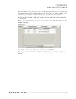
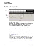
This is the default NV9607 panel configuration page in NV9000-SE Utilities:
Figure 4-1. NV9607 Configuration Page (Default)
After you configure buttons, the appearance of the panel buttons will have changed. The panel but-
tons on this page will show legends, determined from the button type assigned to the button.
At the bottom of the page are two important configuration buttons: ‘Revert to Saved’ and ‘Save’.
The ‘Save’ button commits modifications you have just made. The ‘Revert to Saved’ button
restores the last saved version of the panel configuration, canceling any changes you just made.
Regions of the Configuration Page
Above the ‘Revert to Saved’ and ‘Save’ buttons (always present) there are 4 main regions:
• A graphic representation of the NV9607 panel.
Configurers must click a button “proxy” to select the button for configuration.
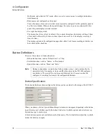
• Button definitions.
In this section, configurers make button assignments, using its pull-down menus and text fields.
See
, following.
• GPIO definitions.
In this section, configurers may define GPIO logic. The control panel has a rear connector that
provides 4 relay outputs and 8 optically isolated inputs. See
tion. (Note that the graphical buttons represent
connector terminals
and not actual buttons.)
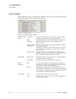
• Panel options.
In this section, configurers may specify the behavioral characteristics of the panel. See
Button
Definition
Section
Panel Image
GPIO
Section
Panel Options
Display Options
Summary of Contents for NV9606
Page 10: ...x Rev 1 0 21 May 10 Table of Contents ...
Page 20: ...10 Rev 1 0 21 May 10 2 Introduction Other NV9607 Functions ...
Page 40: ...30 Rev 1 0 21 May 10 4 Configuration Multi Destination Configuration ...
Page 66: ...56 Rev 1 0 25 May 10 5 Operation Setup Mode ...
Page 72: ...62 Rev 1 1 21 May 10 6 GPIO Configuring Inputs ...
Page 82: ...72 Rev 1 0 21 May 10 8 Misc Topics Power Cord Retention ...
Page 90: ...80 Rev 1 0 18 Aug 10 Index ...


