4
Rev 1.0 • 21 May 10
2. Introduction
Panel Organization
At the rear of the panel are power, serial control, Ethernet, and GPIO connectors:
Figure 2-2. NV9607 Rear
You connect the NV9607 to the NV9000 system using the Ethernet connector.
The serial port is for local diagnostics, as it is for all control panels.
The NV9607 uses external PS0001 power supplies. One will suffice. Two provide redundancy.
The GPIO connector supports the panel’s GPIO functions: 4 outputs and 8 inputs. See
on
Panel Organization
Function Buttons
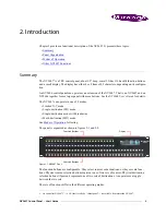
The NV9607 has 4 rows of function buttons. The upper two rows have 24 buttons. The lower two
rows have 34 buttons. The total is 116 function buttons. The set of buttons differ in each of the 4
operating modes. (See
Physical source buttons represent one of two sets of sources. Physical destination buttons (if
present) represent one of two sets of destinations. The panel can be configured with a ‘Source Shift’
button that toggles between the two source pages and a ‘Destination Shift’ button that toggles
between the two destination pages.
Each button has
three
operational levels: high and low tally (green, amber, and sometimes red), and
off. Operators can adjust the low tally levels in increments of 10% using the panel’s menu. Buttons
that are turned off are said to be dark. (Physically, they are actually white or gray.)
S
Generally, green represents a source or a source function and amber represents a destination or
a destination function. However, green and amber also represent other functions.
The function buttons each have clear plastic keycaps under which you may place plastic inserts for
button legends. It is a simple matter to change button legends.
2
Ethernet (RJ-45)
GPIO (DB25)
Power
Serial (RS-422)
2 The NV9607V (virtual panel) has automatically generated button legends. For instance, a source button’s legend is the
source name. Depending on the operating mode, the source button might have up to 3 lines of text: a source from page 1,
a source from page 2, and a destination.
Summary of Contents for NV9606
Page 10: ...x Rev 1 0 21 May 10 Table of Contents ...
Page 20: ...10 Rev 1 0 21 May 10 2 Introduction Other NV9607 Functions ...
Page 40: ...30 Rev 1 0 21 May 10 4 Configuration Multi Destination Configuration ...
Page 66: ...56 Rev 1 0 25 May 10 5 Operation Setup Mode ...
Page 72: ...62 Rev 1 1 21 May 10 6 GPIO Configuring Inputs ...
Page 82: ...72 Rev 1 0 21 May 10 8 Misc Topics Power Cord Retention ...
Page 90: ...80 Rev 1 0 18 Aug 10 Index ...


