background image

NV9604 Control Panel  •  User’s Guide

17

4. Configuration

Commitment Buttons

Configuration Tasks

The person configuring an NV9604 panel will want to consider how best to use the buttons to sup-
port the devices and routers in the router control system at hand. Trade-offs must be made.

In support of that effort, the configurer will do the following:

• Determine whether the panel will run as an NV9602 extension.
• Determine in which mode the panel with this configuration will run.
• Select panel options.
• Assign functions to buttons.

Commitment Buttons 

Two buttons at the bottom of the configuration page are self-explanatory and appear on most con-
figuration pages:

• Revert to Saved. Press this button if you want to discard any recent changes you have made.
• Save. Press this button to commit all your recent changes. 

Neither of these actions is reversible.

Panel Options 

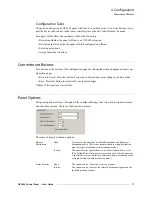
The panel options section, at the right of the configuration page, has two parts: drop-down menus 
and checkbox options. These are the drop-down menus: 

These are its drop-down menu options:

Default 
Destination

None

After a reset, the panel has no default destination and displays no 
destination device. (This is not recommended in single-destination 
mode or single-destination-with-breakaway mode.)

‹device›

The panel uses the specified device as the destination after a reset. 
(The ‘Default State’ button also returns the panel to this destination.)
A specific device is essential for operation in single-destination mode 
or single-destination-with-breakaway mode.)

Status Monitor

None

The current source video is not sent to a monitor. 

‹device›

The current source video for the selected destination appears on the 

specified monitor (device).

Summary of Contents for NV9604

Page 1: ...NV9604 Control Panel User s Guide Miranda Technologies Inc 3499 Douglas B Floreani Montreal Quebec Canada H4S 2C6...

Page 2: ...Reverse engineering of the software is prohibited Due to continued product development the accuracy of the information in this document may change without notice The information and intellectual prop...

Page 3: ...s your needs In the event that problems arise that you cannot resolve or if there are any questions regarding this equipment or information about other products manufac tured by Miranda please contact...

Page 4: ...in place for RoHS compliance that includes significant invest ment in our manufacturing process and a migration of Miranda product electronic components and structural materials to RoHS compliance It...

Page 5: ...ns The Ground symbol represents a protective grounding terminal Such a terminal must be connected to earth ground prior to making any other connections to the equipment The fuse symbol indicates that...

Page 6: ...er fuse replacements to qualified service personnel To avoid explosion do not operate this equipment in an explosive atmosphere Have qualified service personnel perform safety checks after any service...

Page 7: ...way 5 Limited X Y Mode 5 Under NV9602 Control 5 Multi Destination Mode 5 Under NV9602 Control 6 Secondary Modes 6 Other NV9604 Functions 6 Chapter 3 Installation 7 Package Contents 7 Installation 8 In...

Page 8: ...Source 26 Undefined 26 Lock Protect and Release 26 Takes 27 Case 1 Stand Alone Panel Single Destination Mode 27 Case 2 Stand Alone Panel X Y Mode 27 Case 3 NV9602 Extension Single Destination Mode 27...

Page 9: ...arily Chapter 5 Operation provides operating instructions This chapter is for operators primarily Chapter 6 Technical Details provides electrical mechanical and environmental specifications product dr...

Page 10: ...ed throughout this guide The term control panel refers to the NV9604 control panel and to NV96xx control panels in general High tally means that a button is brightly illuminated High tally usually mea...

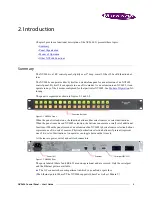
Page 11: ...Front When the panel is stand alone the function buttons either select sources or select destinations When the panel is used as an NV9602 extension the buttons can execute a small set of additional fu...

Page 12: ...and low tally levels in increments of 10 Buttons that are turned off are said to be dark Physically they are actually white or gray S Generally green represents a source or a source function and amber...

Page 13: ...NV9602 or NV9604 Limited X Y Mode In limited X Y mode takes occur from a single source to a single destination Destinations are selectable Takes are all level Pressing a source button completes the ta...

Page 14: ...destination mode Secondary Modes The NV9604 of itself has no secondary modes The NV9604 has a limited self test capability but no setup mode in which to change its panel ID To change the panel ID you...

Page 15: ...you find equipment damage unrelated to shipping please contact technical support Refer to Technical Support Con tact Information on page iii Depending on your order the NV9604 items that can ship inc...

Page 16: ...eed to obtain the latest version of this NV9000 configuration software You may use the Panel IP Configuration Utility if you want to your NV9604 to have a static IP address with respect to the NV9000...

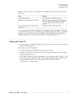
Page 17: ...Follow these steps to set the panel ID 1 If you have more than one NV9604 to set up choose one of them 2 Apply power to the panel Connect one panel to the appropriate panel router network of your NV90...

Page 18: ...will get a message allowing you to change the panel ID 6 Click Change ID A window appears in which you can enter a new panel ID 7 Change the panel ID to a suitable value Make a note of the value 8 No...

Page 19: ...der after you install your NV9604 control panel s 1 Do the buttons illuminate When an NV9604 powers up one or more of its buttons are sup posed to turn green or amber Did it pass the panel test mentio...

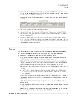
Page 20: ...0 18 Aug 10 3 Installation Testing You can test a take using the NV9602 NV9604 pair Press a destination or a source on the NV9604 to see if the destination or source is identified in the display of th...

Page 21: ...s an extension to an NV9602 control panel As an extension it follows the mode in which the NV9602 was configured The NV9602 has 4 operating modes Single Destination Mode Single Destination Mode with B...

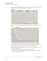
Page 22: ...eld In the ID field enter the panel ID you assigned to the panel in the System Management page You can change the panel ID of an NV9604 only in NV9000 SE Utilities Give a name to the panel in the name...

Page 23: ...Click Previous to go back the previous page Click Cancel to terminate the entry operation S There are 2 other buttons Suffix and Navigate both dim disabled These do not apply to the NV9604 Return to...

Page 24: ...onfiguration buttons Revert to Saved and Save The Save button commits modifications you have just made The Revert to Saved button restores the last saved version of the panel configuration canceling a...

Page 25: ...e made Save Press this button to commit all your recent changes Neither of these actions is reversible Panel Options The panel options section at the right of the configuration page has two parts drop...

Page 26: ...r high tally Use the arrow buttons to scroll to a value The values range from 10 to 100 in increments of 10 percent Low Tally Illumination The default is 60 Sets the panel s button illumination for lo...

Page 27: ...rce button one drop down menus appear Destination Device NV9602 extension you have checked Use as Slave Panel When you assign a destination button two drop down menus appear Destination Device 1 and D...

Page 28: ...to your configuration Stand alone panel When you assign a source button one drop down menus appear Source Device NV9602 extension you have checked Use as Slave Panel When you assign a source button tw...

Page 29: ...e buttons are of two colors green and amber Green generally represents sources and source functions amber generally represents destinations and destination functions but the colors are also used for o...

Page 30: ...en the two sets of sources Limited X Y Mode In limited X Y mode takes occur from a single source to a single destination Destinations are selectable Takes are all level Pressing a source button comple...

Page 31: ...on the NV9602 and NV9604 Destination Shift Destination shift applies only in Limited X Y mode The concept is much like source shift Each destination button can represent two destinations A Destinatio...

Page 32: ...ess it again to remove hold mode Limited X Y In limited X Y mode this button allows you to perform a gang or dub switch In hold mode destination selections are cumulative and not mutually exclusive Fo...

Page 33: ...y any mode X Destination The button selects a destination If the NV9604 is an NV9602 extension the destination name appears in the Destination display of the NV9602 The destination is the target of an...

Page 34: ...on the NV9602 toggles the panel between source set 1 and set 2 NV9602 extension multi destination mode Multi destination mode applies only when the NV9604 is an NV9602 extension and the NV9602 is in...

Page 35: ...e NV9602 display 2 Optionally press Source Shift on the NV9602 to toggle between the source sets 3 Press a source button on the NV9602 or NV9604 to complete the take The Status field of the NV9602 dis...

Page 36: ...ed Follow these steps 1 Optionally press Source Shift on the NV9602 to toggle between the source sets 2 Press a source button on the NV9602 to complete the take The Status field of the NV9602 display...

Page 37: ...will reach the button test All the buttons turn off Press any button to test it If the button is working properly it will flash a few times rapidly Pressing the self test button will terminate the bu...

Page 38: ...30 Rev 1 0 18 Aug 10 5 Operation Self Test...

Page 39: ...fications Specification Detail AC power 90 250 VAC 50 60 Hz auto sensing Inrush current 50 A at 230 VAC cold start at 25 C Input current 2 0 A rms at 115 VAC 1 0 A at 230 VAC Power consumption 14W Reg...

Page 40: ...buttons defined The default panel options are Default destination None Status monitor None High tally illumination 100 Low tally illumination 60 All other options Disabled check boxes clear DHCP The p...

Page 41: ...NV9604 Control Panel User s Guide 33 6 Technical Details Drawings Figure 6 1 Front and Side Views of the NV9604 1 72 43 7 19 0 482 6 NV9604 1 72 43 7 8 61 218 7 9 14 232 2 Right Side View...

Page 42: ...34 Rev 1 0 18 Aug 10 6 Technical Details Drawings Figure 6 2 Rear and Top Views of the NV9604 1 72 43 7 19 0 482 6 17 38 441 5 8 61 218 7 9 14 232 2 1 25 31 8...

Page 43: ...on input port 5 of the AES router and time code on input port 8 of the time code router GPIO General Purpose Input and Output A generic term for the NV9604 s tally interface The tally inter face is ca...

Page 44: ...nation An example of such a device is a VTR System admin istrator The system administrator is the person responsible for installing configuring and maintaining a router control system Tally 1 High or...

Page 45: ...lor 21 23 Button definition section 16 18 Button definitions 16 18 Button functions 18 25 Button legends 4 22 Button test 29 Button types 19 Buttons commitment 17 control panel 2 function 3 4 C Cable...

Page 46: ...9710 GUI 7 Electrical specifications NV9604 31 Electrostatic discharge 7 Email address tech support iii Environmental specifications 32 ESD 7 Ethernet cable 8 Ethernet connector 8 Ethernet port 3 Euro...

Page 47: ...Topics 35 Mode hold 24 limited X Y 5 13 19 21 25 28 multi destination 5 13 19 21 22 25 28 35 36 single destination 4 13 19 21 22 25 27 single destination with breakaway 5 13 19 21 22 24 25 27 X Y 35...

Page 48: ...s and abbreviations 2 Previous page Acrobat 2 Previous source button 6 19 26 Previous view Acrobat 1 Protects 26 destination 26 source 26 R Rack mount 8 Receiving and unpacking shipments 7 Release 26...

Page 49: ...ironmental specifications 32 physical specifications NV9604 31 power specifications NV9604 31 Take scenarios 27 Takes 27 35 Tally high 2 low 2 Technical details 31 Technical support iii Telephone numb...

Page 50: ...42 Rev 1 0 18 Aug 10 Index...

Reviews: