


11. Commissioning
MiR250 Shelf Carrier User Guide (en) 03/2021 - v.1.4 ©Copyright 2021: Mobile Industrial Robots A/S.
121
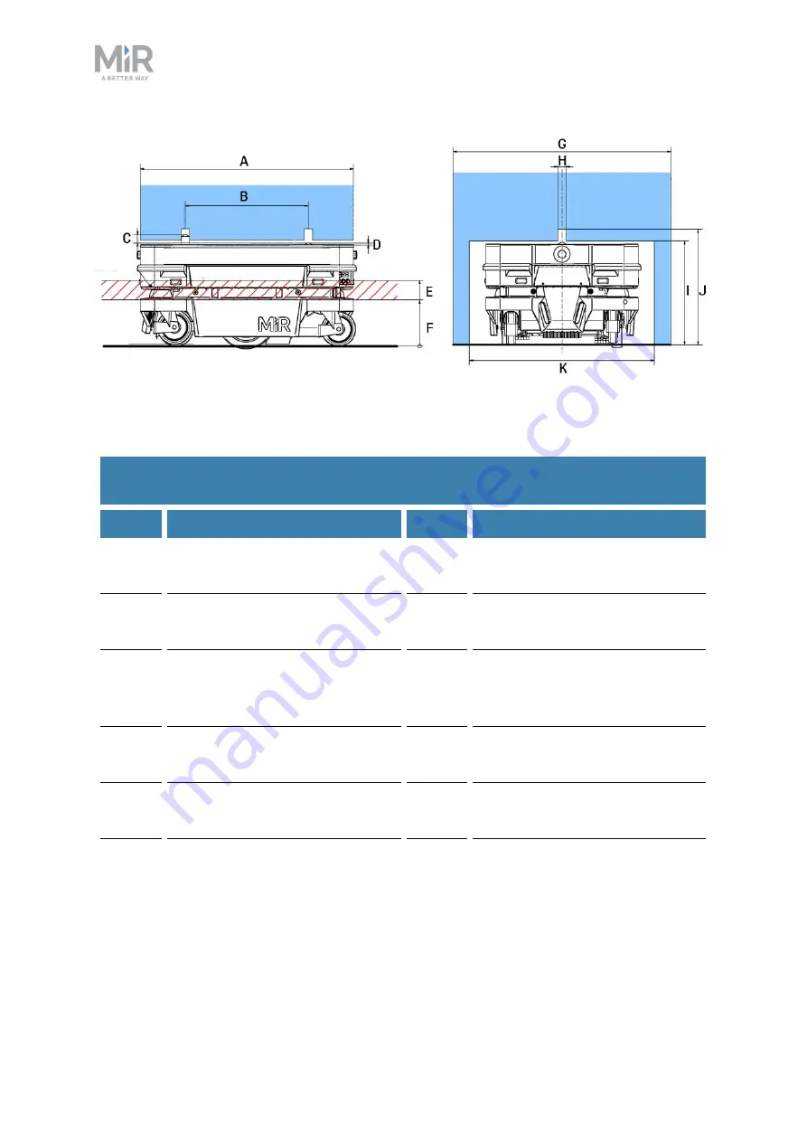
Figure 11.1. Side view (left) and front view (right) of shelf dimensions. The red hatched area is the scanner
zone. Only the legs of the shelf may be located in this area.
Pos.
Description
Pos.
Description
A
Shelf length: maximum 790 mm
B
Distance between centers of
pins: 450 mm (± 1)
C
Pin height when raised: 36.4 mm
D
Pin height when lowered: 6.5
mm
E
Distance from ground to upper
boundary of scanner view: 222
mm (+5/-0)
F
Distance from ground to lower
boundary of scanner view: 152
mm (+0/-5)
G
Shelf width: maximum 800 mm
H
Pin hole diameter: 30.9 mm (±
0.1)
I
Leg height: 383 mm (+3/-0)
J
Pin hole height from ground:
minimum 425 mm
K
Distance between legs:
minimum 680 mm
Table 11.1.
Required shelf dimensions