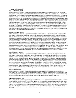
WATER FLOW ADJUSTMENT
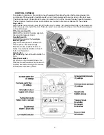
These buttons are used to adjust the flow of solution to the brushes. The buttons can be used to select no
flow or one of five solution flow rates where:
1 bar = .25
gpm
, 2 bars
=
.44
gpm
, 3 bars = .63
gpm
, 4 bars
= .82
gpm
,
and
5 bars = 1
gpm. Either pressing the increase or decrease flow rate buttons adjusts the
volume of solution flow to the brushes and is displayed on the LCD screen and represents the flow rate
setting selected. The flow adjustments can be made in either the
Full function
or
Double scrub
mode.
See
the LCD display section in this book to see the image on the screen looks like when this button is selected.
BRUSH PRESSURE ADJUSTMENT
These buttons adjust the brush pressure. The buttons can be used to select one of five brush pressure
settings:
1 bar =
lightest
, 2 bars
= light
, 3 bars =
medium
, 4 bars =
heavy
,
and
5 bars =
heaviest. The
pressure is adjusted either by pressing the increase or decrease brush pressure buttons. The number of
bars displayed on the LCD screen represents the brush pressure setting selected. The brush pressure
adjustments can be made in either the
Full function
or
Double scrub
mode.
See the LCD display section in
this book to see the image on the screen looks like when this button is selected.
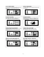
EMPTY SOLUTION TANK INDICATOR
The light inside this icon will be illuminated when the solution tank is empty. At the same instant, the LCD
display will have a flashing bar on the solution flow icon signaling the operator of the solution tank status
and the solution pump shuts off.
See the LCD display section in this book to see the image on the screen
looks like when this button is selected.
RECOVERY TANK FULL INDICATOR
The light inside this icon will be illuminated when the recovery tank is full. At the same instant, the LCD
display will have a flashing bar on the vacuum system icon signaling the operator of the recovery tank
status. After this warning, the rear squeegee will automatically raise and the vacuum motor will shut off
automatically after a few seconds.
See the LCD display section in this book to see the image on the screen
looks like when this button is selected.
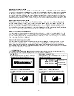
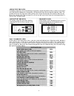
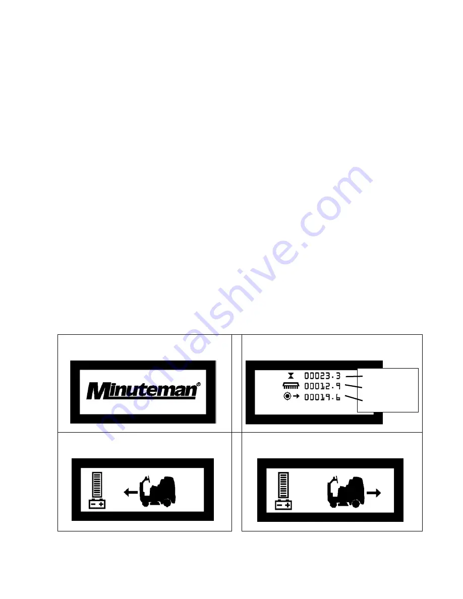
LCD DISPLAYS
The following images below are displayed when selecting the controls or buttons discussed above. The
battery gauge bar will always be displayed whenever the machine is turned on.
KEY SWITCH
When switch is turned on, the Minuteman logo
will appear in the middle of the screen.
INFORMATION BUTTON
Pressing the “i” button will display hours logged on
specific components
DIRECTIONAL SWITCH FORWARD
Silhouette of the machine with arrow pointing
forward.
DIRECTIONAL SWITCH REVERSE
Silhouette of the machine with arrow pointing
backward
Total Hours
Brush Hours
Traction Hours
5
Summary of Contents for SCV28
Page 1: ...SCV 28 32 RIDER SCRUBBER OPERATION SERVICE PARTS CARE ...
Page 3: ...3 ...
Page 31: ...EXPLODED VIEWS MAIN ASSEMBLY I 25 ...
Page 32: ...26 ...
Page 33: ...MAIN ASSEMBLY II 27 ...
Page 34: ...28 ...
Page 35: ...MAINFRAME ASSEMBLY I 29 ...
Page 36: ...MAINFRAME ASSEMBLY II 30 ...
Page 37: ...31 ...
Page 38: ...FRONT DRIVE ASSEMBLY 32 ...
Page 39: ...33 ...
Page 40: ...STEERING ASSEMBLY 34 ...
Page 41: ...35 ...
Page 42: ...LCD HOUSING ASSEMBLY 36 ...
Page 43: ...SOLUTION TANK ASSEMBLY 37 ...
Page 44: ...38 ...
Page 45: ...ELECTRICAL PANEL ASSEMBLY 39 ...
Page 46: ...CONSOLE ASSEMBLY 40 ...
Page 47: ...RECOVERY TANK ASSEMBLY I 41 ...
Page 48: ...42 ...
Page 49: ...RECOVERY TANK II 43 ...
Page 50: ...DIVERTER ASSEMBLY 44 ...
Page 51: ...BATTERY BOX ASSEMBLY 45 ...
Page 52: ...PUMP ASSEMBLY 46 ...
Page 53: ...47 ...
Page 54: ...REAR AXLE ASSEMBLY 48 ...
Page 55: ...SQUEEGEE MECHANISM ASSEMBLY 49 ...
Page 56: ...REAR SQUEEGEE ASSEMBLY 28 50 ...
Page 57: ...51 ...
Page 58: ...REAR SQUEEGEE ASSEMBLY 32 52 ...
Page 59: ...53 ...
Page 60: ...28 CYLINDRICAL SCRUB DECK ASSEMBLY 54 ...
Page 61: ...55 ...
Page 62: ...28 DISC SCRUB DECK ASSEMBLY 56 ...
Page 63: ...57 ...
Page 64: ...32 CYLINDRICAL SCRUB DECK ASSEMBLY 58 ...
Page 65: ...59 ...
Page 66: ...32 DISC SCRUB DECK ASSEMBLY 60 ...
Page 67: ...61 ...
Page 68: ...CYLINDRICAL DECK AND SIDE SQUEEGEE MOUNTING 62 ...
Page 69: ...63 ...
Page 70: ...DISC SCRUBDECK AND SIDE SQUEEGEE MOUNTING 64 ...
Page 71: ...65 ...
Page 72: ...28 SIDE SQUEEGEE RIGHT SIDE 66 ...
Page 73: ...28 SIDE SQUEEGEE LEFT SIDE 67 ...
Page 74: ...32 SIDE SQUEEGEE RIGHT SIDE 68 ...
Page 75: ...32 SIDE SQUEEGEE LEFT SIDE 69 ...
Page 76: ...OFF AISLE WAND ASSEMBLY 70 ...
Page 77: ...71 ...
Page 78: ...PLUMBING DIAGRAM 72 ...
Page 79: ...WIRING DIAGRAMS POWER WIRING 73 ...
Page 80: ...INPUTS TO CONTROLLER 74 ...
Page 81: ...OUTPUTS FROM CONTROLLER 75 ...
Page 82: ...KEYBOARD WIRING 76 ...
Page 83: ...MACHINE SCHEMATIC 77 ...
Page 84: ...1 03 78 ...


