15
14
Chapter 4: Operation
SYSTEM OVERVIEW
This double conversion On-Line UPS protects computers, servers, telecommuni-
cations and electronic equipment from blackouts, brownouts, overvoltages, and
surges. This On-Line UPS converts the input AC to DC and then back to a true sine
wave AC output. The true sine wave output is regulated within 2% of the nominal
output voltage. The Power Factor Correction (PFC) circuitry corrects the input power
factor to within 99% of unity and blocks the load generated harmonic distortion from
getting back on the input AC line. This On-Line UPS provides a continuous true
sine wave output with zero transfer time and great regulation to protect your mis-
sion critical equipment. The UPS will quietly and confidently protect your system
from power anomalies.
The UPS will charge the batteries when the UPS is in the On-Line, the Bypass, or
Economy modes as long as the UPS is connected to utility power and there is an
acceptable AC voltage present. When a blackout, brownout, or an overvoltage
condition occurs while the UPS is in the On-Line mode or the Economy mode; the
UPS will transfer to the battery mode, the On-Battery indicator will illuminate and the
audible alarm will sound once every ten-seconds indicating that the utility power is
lost or unacceptable. When the utility power returns or is at an acceptable level, the
UPS will automatically transfer back to the On-Line mode or the Economy mode
and start recharging the batteries. During an extended outage when there is ap-
proximately two-minutes of backup time remaining the audible alarm will sound
twice every five-seconds. This Low Battery Warning is letting the user know that
they should save all open files and turn off their equipment. When the batteries
reach the predetermined level the UPS will automatically shutdown protecting the
batteries from over discharging. Once the utility power returns the UPS will auto-
matically restart providing safe usable power to the connected equipment and start
recharging the batteries.
The Bypass mode operation: The input utility power 'bypasses' the inverter circuit
and is connected directly to the output of the UPS powering the connected equip-
ment while simultaneously charging the batteries. When a blackout, brownout, or
an overvoltage condition occurs while the UPS is in the Bypass mode the con-
nected equipment will not be backed up. When utility power returns the UPS will
automatically startup in the Bypass mode powering the connected equipment and
resume charging the batteries.
The Economy mode operation: The input utility power 'bypasses' the inverter cir-
cuit and is connected directly to the output of the UPS powering the connected
equipment while simultaneously charging the batteries. When a blackout, brown-
out, or an overvoltage condition occurs the UPS will transfer to the battery mode,
the inverter will turn on powering the connected equipment, the On-Battery indicator
will illuminate and the audible alarm will sound once every ten-seconds indicating
that the utility power is lost or unacceptable. When the utility power returns or is at
an acceptable level, the UPS will automatically transfer back to the Economy mode
and start recharging the batteries.
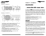
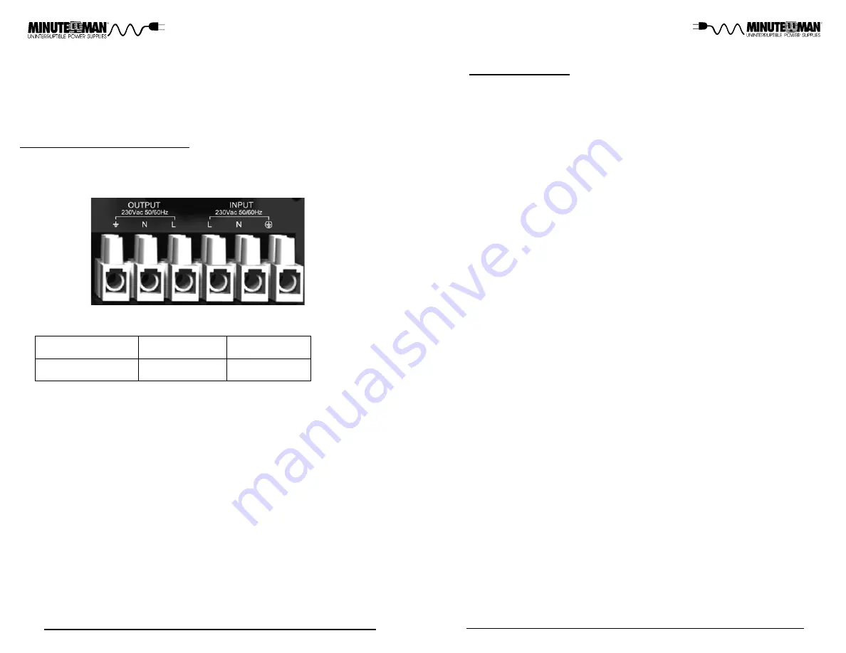
INPUT / OUTPUT CONNECTIONS:
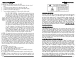
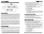
1. Remove the terminal block cover box from the rear panel of the UPS (req-
uires a phillips screwdriver). Refer to the figure below for the input / output
connections.
2. Input / Output cable selection:
60°C / 75°C
Temperature Rating
5/6KVA
#10 AWG (Cu)
8/10KVA
#6 AWG (Cu)
(In accordance with National Electrical Code (NEC), install suitable cond-
uit and bushing.)
NOTE:
Use copper wire only.
3. Before connecting to the input / output terminals read all of the Cautions
and Warning, then observe the following:
a)
Ensure that the UPS is turned off and not connected to the AC sour-
ce or the battery source before any connections are made.
b)
Calculate the power consumption of the load to ensure that an over-
load condition does not occur.
c)
Ensure that the terminal block screws are secured after connecting
the input / output wires. The terminal block screws should be torque
to 18±2Kgf.cm (requires a 3/16" flat-head screwdriver).
d)
Ensure that the UPS is properly grounded.
4. Connect the input utility wires and/or input power cord to the input termi-
nal block and secure.
5. Connect the load wires to the output terminal block and secure.
6. Re-install the terminal block cover box.
The ED8000RT-CU and ED10000RT-CU are hardwire input only. The pins for
the input cable are included. The UPS must be connected to the appropriate
branch protection (circuit breaker) to avoid shock hazard and violation of any
local electrical codes. The branch protection (circuit breaker) shall be in-
stalled near the UPS and shall be easily accessible. The installation of up-
stream and downstream protective devices is highly recommended when the
UPS is connected to the utility power and the load.

