FrameMaker Ver.5.5E(PC) EP3000/EP3010 DIS/REASSEMBLY, ADJUSTMENT
98.05.29
D-67
✽
Requirement
•
With the Scanner positioned correctly with reference to the upper copier frame, there
should be no gap between the Scanner/Mirrors Carriage and the Scanner/Mirrors Car-
riage Positioning Jig.
40-5. OTHER ADJUSTMENTS
(1) Adjustment of the Scanner/Mirrors Carriage Position
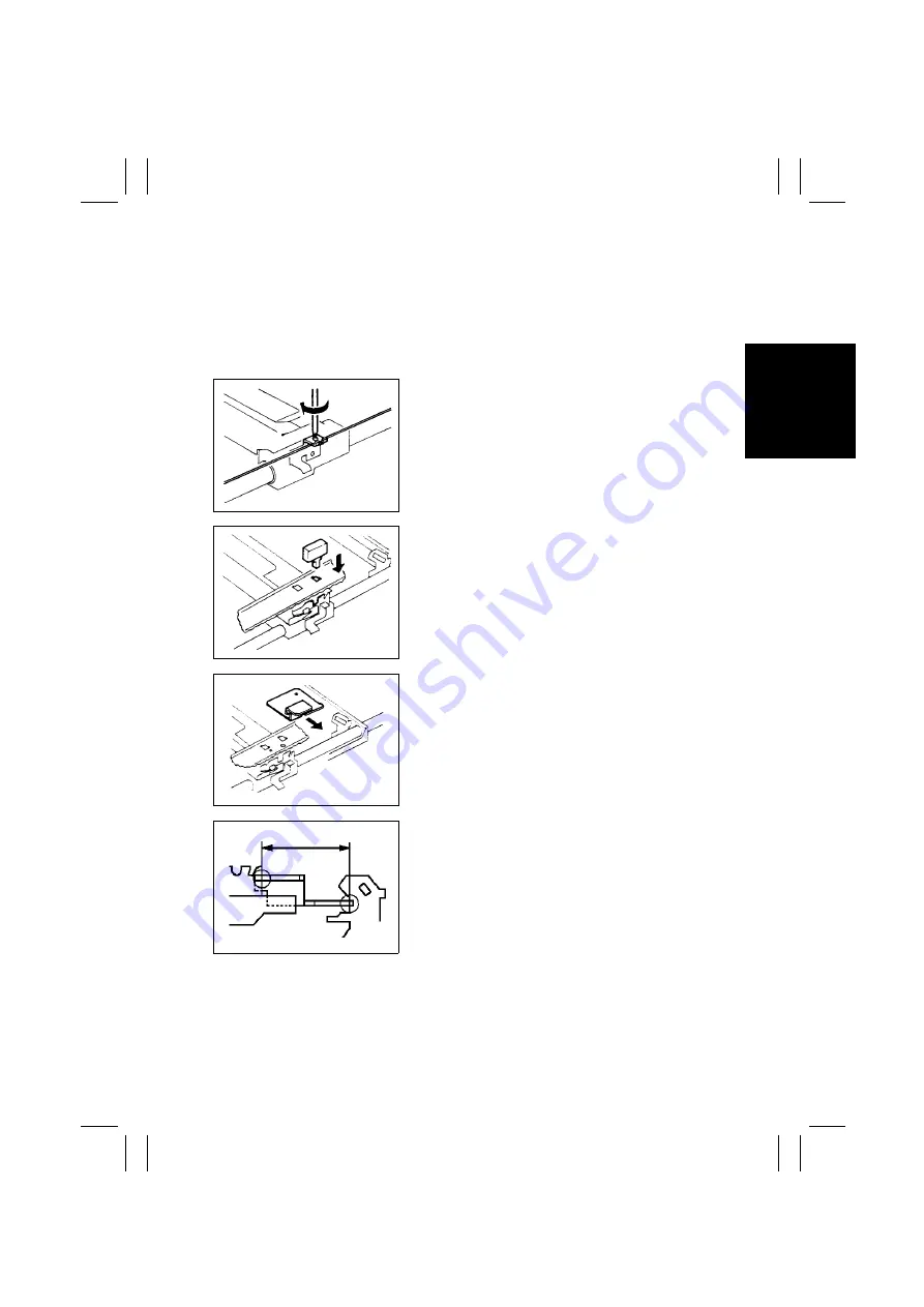
1. Remove the Original Cover, Original Scales, and
Original Glass.
2. Temporarily tighten the screw on the Scanner Drive
Cable Holding Bracket.
1139D051AA
3. Align the rectangular hole in the upper copier
frame with the U-groove in the Scanner, then insert
the Scanner Positioning Jig into the hole.
1139D052AA
4. Install the Scanner/Mirrors Carriage Positioning Jig
between the Scanner and Mirrors Carriage.
1139D248AA
5. Loosen the screw that has been temporarily tight-
ened in step 2. Turn the helical gear of the Scan
Pulley to press the Mirrors Carriage up against the
Scanner/Mirrors Carriage Positioning Jig and the
Scanner.
6. Tighten the screw on the Scanner Drive Cable
Holding Bracket.
1151D055AA


