


2. DISASSEMBLY PROCEDURE
Before
the disassembly
press the upper
lock release button to
the Upper Unit.
Imaging Cartridge.
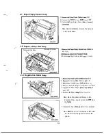
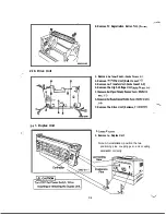
2-1. Outer Cover
Upper Unit Lock Release Button
2-2.
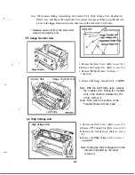
Fusing Unit
1. Remove the Left Cover. (2
2. Remove the Right Cover. (3 screws)
3. Remove the Upper Unit. (2 screws)
4. Remove the Right Front Cover. (1 screw)
5. Remove the Front Cover. (6 screws)
6. Remove the Rear Cover. (2 screws)
1. Remove the Outer Cover. (Refer to section
2-l.)
2. Remove the Fusing Unit. (4 screws, 3
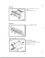
Note: When reassembling the Fusing
Unit, adjust the position of the Image
Transfer Unit.
Pin
D-2
Summary of Contents for 2060
Page 1: ......
Page 2: ......
Page 3: ...S P A 3 1 0 Service Parts Manual September 1996 Revision C 02 ...
Page 4: ......
Page 5: ...WARNING LABELS i ...
Page 31: ... I PRINTING PROCESS I 9 Paper Exit Duplex I Sensor C l ...
Page 51: ...E ADJUSTMENT 1 IMAGE REGISTRATION E 1 ...
Page 52: ... ...
Page 57: ......
Page 61: ......
Page 64: ... 0993 PARTS MANUAL MINOLTA QMS ...
Page 68: ...L H O U S I N G 9C 3 PARTS MANUAL ...
Page 70: ...FRAMES 7 L J P PARTS MANUAL ...
Page 72: ...1 PARTS MANUAL1 5 ...
Page 76: ......
Page 78: ...T R A N S P O R T SFCTION 2 9 E PARTS MANUAL L ...
Page 79: ......
Page 80: ......
Page 81: ......
Page 82: ......
Page 83: ......
Page 84: ...0 a P A R T S M A N U A L ...
Page 86: ... 4 ...
Page 87: ... ...
Page 88: ......
Page 92: ......
Page 93: ... ...
Page 94: ......


