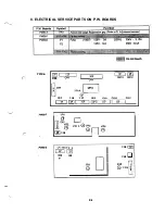
5. ELECTRICAL COMPONENT LAYOUT
M6
PWB-B
PC4
PWB-A
PWB-C
PWB-E
PWB-F
PWB-R
SL2
CL1
s2
Main control Board
2nd Cassette Unit Board
Power Unit
High Voltage Unit
Toner Empty Board
Resistor Board
Main Motor
Fusing Fan Motor
Power Fan Motor
Take-up Solenoid
2nd
Take-up Solenoid
Registration Clutch
Power Switch
Interlock Switch
Duplex Cover Switch
2nd Paper Size Switch
PC1
PC3
PE2
Take-up
Paper
Sensor
Registration
Paper Empty Sensor
Paper Near-empty Sensor
2nd Paper Empty Sensor
2nd
Near-empty Sensor
Heater Lamp
Toner Empty Sensor
Thermistor
Thermostat
Duplex
. . .._..“..... . .
. . . . .
Summary of Contents for 2060
Page 1: ......
Page 2: ......
Page 3: ...S P A 3 1 0 Service Parts Manual September 1996 Revision C 02 ...
Page 4: ......
Page 5: ...WARNING LABELS i ...
Page 31: ... I PRINTING PROCESS I 9 Paper Exit Duplex I Sensor C l ...
Page 51: ...E ADJUSTMENT 1 IMAGE REGISTRATION E 1 ...
Page 52: ... ...
Page 57: ......
Page 61: ......
Page 64: ... 0993 PARTS MANUAL MINOLTA QMS ...
Page 68: ...L H O U S I N G 9C 3 PARTS MANUAL ...
Page 70: ...FRAMES 7 L J P PARTS MANUAL ...
Page 72: ...1 PARTS MANUAL1 5 ...
Page 76: ......
Page 78: ...T R A N S P O R T SFCTION 2 9 E PARTS MANUAL L ...
Page 79: ......
Page 80: ......
Page 81: ......
Page 82: ......
Page 83: ......
Page 84: ...0 a P A R T S M A N U A L ...
Page 86: ... 4 ...
Page 87: ... ...
Page 88: ......
Page 92: ......
Page 93: ... ...
Page 94: ......

