3. Device description | 3.3 - Housing | 28
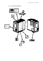
3.3.4 Sticker
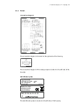
Connection diagram
DIGITAL IN
LC SUPPLY
DI1 DI2 DI3
DIGND
9
10
11
12
5
7
6
8
V+
PE
PE
V-
SIGN
SENSE
M+ M-
S+ S-
1
2
3
4
G
re
en
G
re
y
W
hi
te
B
la
ck
R
ed
B
lu
e
24 VDC / 9 W
POWER SUPPLY
DIGITAL OUT
RS 485/422
13 14
15
16
-
+
PE
PE
23
22
21
24
20
19
18
17
DO1 DO2 DO3
DOGND
RxB
TxB
R
D
RxA
TxA
The connection diagram is located on the right side of the housing.
The connection diagram of the analog output is located on the left side of the
housing.
Identification plate
The identification plate is located on the left side of the housing.


