


4.5 Hardware construction
4.5.1
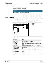
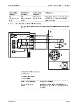
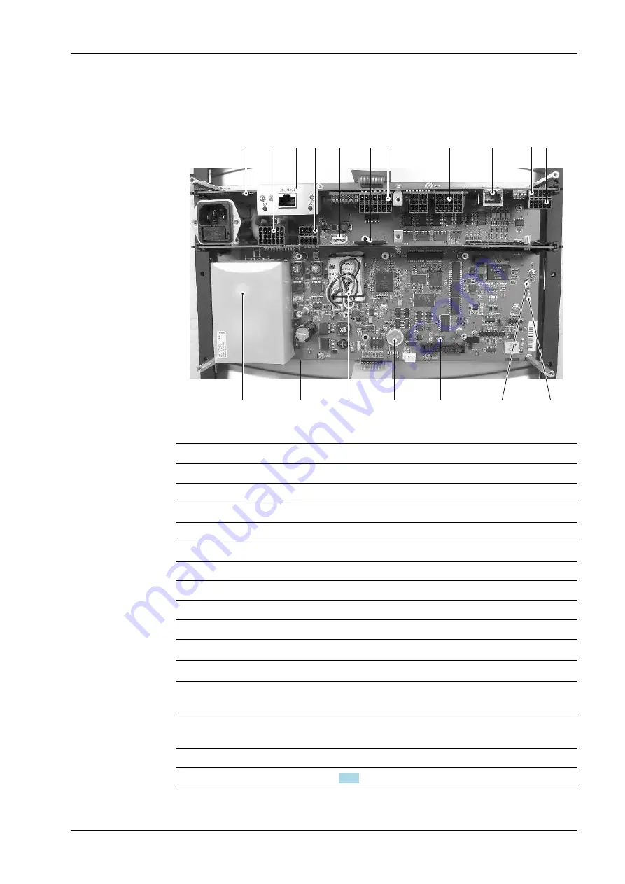
Main board
11
10
1
9
8
7
4
5
6
2
3
12
13
15
14
17
18
16
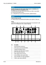
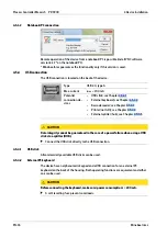
The following elements are located on the main board:
No.
Description
1
Reset key
2
Digital outputs (internal)
3
Slot for ieldbus cards, FB option
4
Digital inputs (internal)
5
USB connection
6
SD card slot
7
Slot for optional cards, option 1
8
Slot for optional cards, option 2
9
Ethernet port, internal
10
Connection for RS
‑
485 interface, internal
11
Connection for RS
‑
232 interface, internal
12
CAL switch 1 (see [Commissioning] - [Overwrite protection] - [CAL switch] in the
PR 5900 operating instructions)
13
CAL switch 2 (see [Commissioning] - [Overwrite protection] - [CAL switch] in
the PR 5900 operating instructions)
14
SIL chip
15
Clock battery (see Chapter
4 Device installation
Process Controller Maxxis 5 PR 5900
Minebea Intec
EN-33
Summary of Contents for Maxxis 5
Page 137: ......


