background image

— MIN.INIT

3.6 - Minimum load for application

— 1 DIGIT

3.6.1 - 1 digit*

— 2 DIGIT

3.6.2 - 2 digits

— 5 DIGIT

3.6.3 - 5 digits

— 10 DIGT

3.6.4 - 10 digits

— 20 DIGT

3.6.5 - 20 digits

— 50 DIGT

3.6.6 - 50 digits

— 100 DIG

3.6.7 - 100 digits

7.12.4

Limits

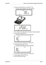
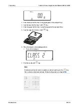
To use the Classiication application, you need to enter the delimiters that separate one

class from another. Limits between the individual weigh classes are required for the

classiication. The lower limit of Class 1 is deined by the preset minimum load. The other

classes are conigured by deining their upper limits. There are two ways to enter the

delimiters for classes 1 through 3 (or 5):

-

By saving

the weight value indicated

: Each upper limit value, with the exception of

the highest class, is entered using the keypad or by saving the weight value of a load

on the weighing platform.

-

By entering

a percentage

: The upper value of Class 1 is entered using the keypad or

by saving the value indicated. Upper limits for the other classes are deined by

entering a percentage of deviation from the upper limit of Class 1, using the keypad.

Example

: Enter 100 g as the upper limit of Class 1. Then enter 15%.

When working with 3 classes, this yields the following weight classes:

-

Class 0: up to the minimum load

-

Class 1: > minimum load – 100 g

-

Class 2: > 100 g – 115 g

-

Class 3: > 115 g – maximum load

When working with 5 classes, this yields the following weight classes:

-

Class 0: up to the minimum load

-

Class 1: > minimum load – 100 g

-

Class 2: > 100 g – 115 g

-

Class 3: > 115 g – 130 g

-

Class 4: > 130 g – 145 g

-

Class 5: > 145 g – maximum load

Note:

The entered value remains active until deleted by pressing the

key or until

overwritten by a new value. It remains saved after the scale is switched of.

7.12.5

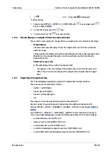
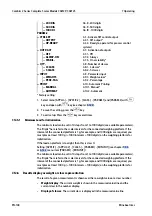
Available Parameter Settings

Minimum load for application, see chapter

7.12.5.1

).

Menu tree of the parameters Classiication:

PARAM.1

7 Operating

Combics 2 Series Complete Scales Models CAW2P, CAW2S

Minebea Intec

EN-147

Summary of Contents for CAW2P

Page 1: ...eries Complete Scales Models CAW2P CAW2S Operating Instructions 98648 018 44 Edition 1 1 0 03 12 2021 Minebea Intec Bovenden GmbH Co KG Leinetal 2 37120 Bovenden Germany Tel 49 551 309 83 0 Fax 49 551...

Page 2: ...iied personnel In correspondence concerning this product the type name and release number serial number as well as all license numbers relating to the product have to be cited Note This document is pa...

Page 3: ...ction 11 2 4 5 IP protection 11 2 4 6 Use in legal metrology 11 2 5 Failure and excessive stress 11 2 6 Repairs and maintenance 12 2 6 1 General information 12 3 Device description 13 3 1 Overview of...

Page 4: ...ing menu settings 43 5 5 Default settings 43 5 5 1 Set the language 44 5 5 2 Setting up password protection 45 5 5 3 Modify or delete password protection 46 5 5 4 Printing out parameter settings 46 5...

Page 5: ...4 3 WP 1 91 6 4 4 WP 2 91 6 4 5 FLEXINF 92 6 4 6 ALIB MEM 92 6 5 LANGUAG 92 6 6 ADC CON 92 6 6 1 STANDRD 92 6 6 2 VERIF 93 7 Operating 95 7 1 Weighing 95 7 1 1 Automatic tare 95 7 1 2 Minimum load for...

Page 6: ...iece weight 114 7 7 5 Available Parameter Settings 115 7 7 6 Example Counting 118 7 8 Neutral Measurement nM application 120 7 8 1 Exit application delete parameters 120 7 8 2 Tare function 120 7 8 3...

Page 7: ...t or class representation 148 7 12 7 Digital Input Output Interface 149 7 12 8 Example Classiication 150 7 13 Totalizing applications 152 7 13 1 Exit application delete parameters 152 7 13 2 Tare func...

Page 8: ...at 176 8 5 Data output format 178 8 5 1 Output format with 16 characters without header 178 8 5 2 Output format with 22 characters 180 8 5 3 External Keyboard Functions PC Keyboard 182 8 6 Conigure da...

Page 9: ...198 12 4 CAW S Model Resolutions 199 13 Appendix 201 13 1 Documents List 201 13 2 Minebea Intec Services 201 13 3 Plates and marks 201 13 4 Certiicates 202 13 5 General Password 202 Combics 2 Series...

Page 10: ...sures for preventing hazards are not followed DANGER Warning of personal injury DANGER indicates death or severe irreversible personal injury which will occur if the corresponding safety measures are...

Page 11: ...ment may occur if appropriate safety measures are not observed Take the corresponding safety precautions Note User tips useful information and notes 1 6 Hotline Phone 49 551 30983 111 Fax 49 551 30983...

Page 12: ...rejection of the goods a claim must be iled with the carrier immediately A Minebea Intec sales or service organization must also be notiied 2 4 Before operational startup NOTICE Perform visual inspec...

Page 13: ...s with fastened plugs must be carried out and checked by a specialist If a data output or battery connection is subsequently installed keep the plugs Use a cap or similar to protect the data output fr...

Page 14: ...ecting additional devices from the data outputs the must irst be disconnected from the mains Only clean the device according to the cleaning instructions see Chapter 9 Care and maintenance Combics 2 S...

Page 15: ...rk with Built in programs for applications some combinable Counting Neutral measurement Averaging animal weighing Percentage weighing Checkweighing Classiication Totalizing Net total Automatic zeroing...

Page 16: ...ion see Chapter 3 3 3 2 6 General function keys Zeroing taring switching functions calibration adjust ment printing data output see Chapter 3 3 3 1 7 Changing the weighing platform WP 8 Switch on of 9...

Page 17: ...speciic plug 3 Vent valve 1 5 Nm 4 Input for menu access switch standard or legal for trade mode for WP 1 and or WP 2 5 Weighing platform WP 1 and or WP 2 connection 1 2 CAW2P Legend No Description 1...

Page 18: ...imensions 3 2 1 1 Indicator scale diagrams Dimensions in millimeters A A M4 3x internal thread Keyboard diferent than pictured Combics 2 Series Complete Scales Models CAW2P CAW2S 3 Device description...

Page 19: ...ng elements 3 3 1 General information There are two possible displays Display for measuring mode see Chapter 3 3 3 2 1 Display in the menu mode see Chapter 3 3 3 2 2 3 Device description Combics 2 Ser...

Page 20: ...assiication 6 General function keys see Chapter 3 3 3 1 3 3 3 Display Operating elements see Chapter 3 3 3 1 Display notiications see Chapter 3 3 3 2 Navigating the menu see Chapter 3 3 3 3 Entering n...

Page 21: ...hapters for the respective applications Delete key Clear initialization values or totalizing memory when entering a value with the numeric keypad this clears the last digit entered Reference value key...

Page 22: ...the applied gross weight 0 lower load limit 100 upper load limit or Display of the measured value in relation to a set point for the checkweighing and classiication applications Minimum for checkweig...

Page 23: ...Neutral measurement Percentage weighing Averaging animal weighing 17 Appl 2 Checkweighing Classiication Check against zero Manual dosing against zero 17 Appl 3 Totalizing Net total 18 Zeroing symbol...

Page 24: ...ription 4 First level in the number menu 5 Second level in the number menu 6 Third level in the number menu 7 Current active setting 3 3 3 3 Navigating in the menu The keys under which white arrows ar...

Page 25: ...switch to measurement mode Printout of the menu settings from the current position printout of the info da ta 3 3 3 4 Entering numbers and letters Enter numeric values directly using the 10 key keybo...

Page 26: ...r the safety of the device Do not subject the device to extreme temperatures moisture shocks and vibrations CAUTION Risk of injury If the load plate is lifted using a suction lifting tool wear gloves...

Page 27: ...et up to be precisely horizontal Therefore the weighing platform must be re leveled every time it is moved to a diferent location Wear protective clothing safety shoes and if necessary gloves When lif...

Page 28: ...n the adjustable feet using a wrench A F17 Extend or retract the adjustable feet using an Allen key A F5 Use the adjustable feet to align the weighing platform so that the air bubble of the level indi...

Page 29: ...d specialized training from Minebea Intec CAUTION Property damage and or personal injury are possible Disconnect the equipment from the power supply before starting connection work CAW2S IP69K 4 2 7 1...

Page 30: ...n from the wires of the connecting cable and aix ferrules to the wire ends 1 Remove the dummy plug from the hole on the intended for this purpose 2 Insert the enclosed cable gland through the hole and...

Page 31: ...diagrams see Chapter 4 2 8 2 7 For the assignment of colors signals refer to the operating instructions data sheet for the weighing platform Any unused cables must be properly insulated 8 When connect...

Page 32: ...ontrol Output set 6 5V switched 21 5 V switched 7 GND 22 PS 2_Data 8 GND 23 PS 2_Clock 9 n c 24 GND 10 LINE_OUT 31 Not assigned 11 Clear to Send CTS 32 Not assigned 12 Data Terminal Ready DTR 33 Not a...

Page 33: ...GND 6 Calibration Lock 16 GND Interface PCB for ADC 10 000e option A20 or for Types MCE UCE RCE 1 Com 1 PS 2 3 A20 2 Weighing platform Interface 2 Indicator connection LED connection Terminal assignme...

Page 34: ...TxD 14 LINE_OUT 5 GND 15 GND 6 Calibration Lock 16 GND 4 2 8 2 Pin Assignment Chart Model CAW2P IP44 protection see chapter 4 2 8 2 1 Connecting an IS Weighing Platform see chapter 4 2 8 2 2 Cabling D...

Page 35: ...minal Ready DTR 8 Internal ground GND 21 Ground power supply GND 9 Not assigned 22 Not assigned 10 Not assigned 23 Not assigned 11 12 V for printer 24 Power supply 15 25 V peripherals 12 RES_OUT 25 5...

Page 36: ...erence to radio communications For information on the speciic limits and class of this equipment please refer to the Declaration of Conformity Depending on the particular class you are either required...

Page 37: ...ION Property damage and or personal injury are possible The power connection must be made in accordance with the regulations applicable in your country Make sure that the voltage rating printed on the...

Page 38: ...ical load e g compressors large machinery etc 4 2 8 2 7 Connecting a Barcode Scanner Accessory Order No YBR05PS2 For CAW2P models For CAW2S models 4 2 9 Operating limits You should not exceed the high...

Page 39: ...dropping objects onto the platform from considerable heights and do not expose the platform to side impacts or shock loads The weighing platform complies with the loads speciied in the standard DIN IE...

Page 40: ...roduct Order No Veriiable data printer with date time and statistics functions with LCD display YDP21 5 x 40 m paper rolls for data printer 6903952 Replacement ink ribbon cartridge for printer 6906918...

Page 41: ...cable ends on 9 pin D SUB plug 30 cm on request Proibus adapter cable for CAW P 25 pin D SUB plug on 9 pin D SUB socket 30 cm on request 1 Suitable for use in zones 2 22 DeviceNet use only with stainl...

Page 42: ...er input 0 30 V YSB01 Peripheral devices Control display red green red YRD04 Barcode scanner 120 mm scanning width with cable for connection to CAW2P YBR05PS2 Flexible formatting options for printouts...

Page 43: ...able for CAW P IP 44 Connection cable 25 pin D SUB plug on Combics side for printer YDP05 ZD420 9 pin D SUB plug 6 m YCC01 01CISLM3 for PC 9 pin D SUB socket 6 m 7357314 for Minebea Intec scales 25 pi...

Page 44: ...display then returns to the previous screen content 1 only if menu item SIGNAL 8 2 is switched on see chapter 6 3 8 1 5 2 Switching on the device Whenever it is switched on the device performs a self...

Page 45: ...he menu mode by selecting the desired parameters These are summarized into the following groups 1st menu level menu structure see Chapter 6 ANWEND Application parameters see Chapter 6 1 FN K Function...

Page 46: ...ey The display for selecting the application program APPLIC appears 3 Press key until the menu item LANGUAG for the language setting is displayed 4 Press key to access the language setting sub menu LA...

Page 47: ...der to make further settings if necessary 1 Switch on the device with key 2 During the display test briely press the key The display for selecting the application program ANWEND appears 3 Press key un...

Page 48: ...ice menu you can perform 5 Press key until BEN CODE is displayed 6 Press key to open the menu item BEN CODE The position in which the irst character needs to be entered lashes in the display 7 Use the...

Page 49: ...AUFLOES 1 19 2 Resolution2 EMPFND 1 1 19 3 Sensitivity 1 EMPFND 2 1 19 4 Sensitivity 2 EMPFND 3 1 19 5 Sensitivity 3 EMPFND 4 1 19 6 Sensitivity 4 NUL PNKT 1 19 7 Zero point SPEICH 1 19 8 Save parame...

Page 50: ...only visible in service mode 2 only for ADCs from the older Combics generation 5 6 2 Activating the service mode Menu SETUP BEN CODE If a code word is requested at this point enter the service access...

Page 51: ...the geographic data entered is as follows 51 00 north latitude 513 m altitude above sea level then the scale can be operated anywhere in Germany The gravitational acceleration for Germany Zone D is 9...

Page 52: ...1 20 see also Chapter 6 3 1 1 1 SM only visible in service mode Procedure If the device is part of a veriied weighing system this can only be done by breaking the seal The scale must then be re calib...

Page 53: ...the calibration and linearization weights in the Setup menu for the irst weighing platform under WP 1 and for the second weighing platform under COM1 WP 2 UNICOM WP 2 or COM WP The settings are appli...

Page 54: ...default weights menu item LIN EXT 1 9 6 External linearization with the linearization weights entered under menu item HND EXT G 1 18 menu item LIN E USR 1 9 7 Internal linearization only for WP 2 men...

Page 55: ...T 1 9 Procedure Menu SETUP WP 1 INTERN PARAM 1 CAL JUST 1 9 see also Chapter 6 3 1 1 1 1 For scales used in legal metrology Open the locking switch see Chapter 7 2 1 2 Zero the weighing platform by pr...

Page 56: ...default weights see Chapter 6 3 1 1 1 menu item CAL JUST 1 9 Procedure 7 Repeat the procedure for all required linearization weights After the inal linearization weight has been stored a prompt appea...

Page 57: ...ee Chapter 6 3 1 1 1 menu item CAL JUST 1 9 Procedure 2 Place the preload weight onto the weighing platform 3 Start Set Preload with key After a short time the preload is adopted and the automatically...

Page 58: ...eight in the SETUP menu for the irst weighing platform under WP 1 and for the second weighing platform under COM1 WP 2 UNICOM WP 2 or COM WP The settings are applied in the corresponding number menu u...

Page 59: ...ndividual values for each of the load cells menu items EMPFND 1 1 19 3 EMPFND 4 1 19 6 or enter the average value across all cells menu item EMPFND 1 1 19 3 1 Open the locking switch see Chapter 7 2 1...

Page 60: ...tic taring and automatic printing see chapter 6 1 5 AUT STRT For On automatic start of application with the last saved initialization data see chapter 6 1 6 CLER CF Selective deleting with the key see...

Page 61: ...solution for calculation of reference piece weight DISP ACC 3 9 1 Display accuracy 10 FOLD 3 9 2 plus 1 decimal place 10 fold 100FOLD 3 9 3 plus 2 decimal places 100 fold SAVE WT 3 11 Parameter for sa...

Page 62: ...for saving weight values STABIL 3 11 1 With stability ACC STAB 3 11 2 With increased stability REF WP 3 13 Reference weighing instrument NO WP 3 13 1 No platform selected WP 1 3 13 2 Weighing platform...

Page 63: ...APPLIC 1 Basic weighing function Counting Neutral measurement nM Animal weighing Weighing in percent applications PERCENT Weighing in percent application MIN INIT 3 6 Minimum load for application 1 D...

Page 64: ...eighing range 30 170 4 2 1 30 170 10 MAX L 4 2 2 10 ininity CTRL SET 4 3 Activate SET control output OUTPUT 4 3 1 SET output OP READY 4 3 2 Ready to operate for process control systems OUTP ACT 4 4 Ac...

Page 65: ...INIT 3 6 Minimum load for application 1 DIGIT 3 6 1 1 digit 2 DIGIT 3 6 2 2 digits 5 DIGIT 3 6 3 5 digits 10 DIGT 3 6 4 10 digits 20 DIGT 3 6 5 20 digits 50 DIGT 3 6 6 50 digits 100 DIG 3 6 7 100 dig...

Page 66: ...e chapter 6 1 3 1 TOTALIZ Totalizing application see chapter 6 1 3 2 APPLIC 3 Checkweighing Classiication applications NET TOT Net total application MIN INIT 3 6 Minimum load for application 1 DIGIT 3...

Page 67: ...s AUTO SAV 3 16 Autosave OFF 3 16 1 Of ON 3 16 2 On PRT SAV 3 17 Individual Component printout when saved OFF 3 17 1 Automatic printing of HEADCOM Automatic printing on EACH TIM 3 17 2 Print the entir...

Page 68: ...ast settings AUTOMAT 3 8 1 Automatic on MANUAL 3 8 2 Manual of CLER CF Selective deleting with the key ALL APPL 3 24 1 Deletes all applications SEL APPL 3 24 2 Only deletes selected application APPLIC...

Page 69: ...ptional interface see chapter 6 3 3 COM WP 10 000e ADC setting see chapter 6 3 4 CTRL IO Universal input and digital IOs setting optional see chapter 6 3 5 BARCODE Settings for barcode function see ch...

Page 70: ...nternal see chapter 6 3 1 1 OFF Of COM 1 Function is locked UNICOM Only when Unicom is equipped RS 232 RS 232 interface Menu parameters depending on the connected complete scale RS 485 RS 485 interfac...

Page 71: ...lay SHORT 1 4 2 Short delay AVERAG 1 4 3 Average delay LONG 1 4 4 Long delay TARE Stability W O STB 1 5 1 Without stability W STAB 1 5 2 At stability AUT ZERO 1 6 Auto zero ON 1 6 1 On OFF 1 6 2 Of 1...

Page 72: ...on IS scales only 1 LIN EXT 1 9 6 External linearization with standard weights1 LIN E USR 1 9 7 External linearization with user weights1 SET VORL 1 9 8 Set preload CLR VORL 1 9 9 Delete preload GESPR...

Page 73: ...8 Save parameters GEOG DAT 1 20 Calibration site geographical data or alternatively gravitational acceleration at installation site SM BREITE 1 20 1 Latitude in degrees HOEHE 1 20 2 Altitude in meter...

Page 74: ...NIT 3 3 3nd weight unit depends on the weighing platform type USERDEF 3 3 1 User deined o GRAMS 3 3 2 Grams g KILOGR 3 3 3 Kilograms kg CARATS 3 3 4 Carats ct1 POUNDS 3 3 5 Pounds lb1 OUNCES 3 3 6 Oun...

Page 75: ...for weighing platform 1 INTERN Internal ADC CON Analog Digital converter coniguration ADC SM STANDRD Standard coniguration RANGES Ranges SINGLE Single range mode MULT INT Multi interval mode MULT RNG...

Page 76: ...h default weight CAL E USR 1 9 3 External calibr adjustment with user deined weight CAL INT 1 9 4 Internal calibr adjustment for IS scales only GESPRT 1 9 10 Key locked HND EXT G 1 18 Manual entry of...

Page 77: ...5 1 2 300 600 5 1 3 600 1200 5 1 4 1200 2400 5 1 5 2400 4800 5 1 6 4800 9600 5 1 7 9600 19200 5 1 8 19200 PARITY 5 2 Parity SPACE 5 2 2 Space Only if 7 data bits is selected ODD 5 2 3 Odd EVEN 5 2 4...

Page 78: ...ates AFTR 100 6 3 7 100 display updates COM 1 Settings for the RS 232 interface DAT PROT Data protocols SBI SBI protocol FORMAT 7 Data outputs format LINE 7 2 Data output Line format 16 CHAR 7 2 1 For...

Page 79: ...TER Printer coniguration YDP20 YDP20 printer see chapter 6 3 2 3 1 YDP14IS YDP14IS printer LINE Strip printer LABEL Label printer UNI PRI Universal printer see chapter 6 3 2 3 2 YDP04 5 YDP04 5 printe...

Page 80: ...5 4 Handshake mode SFTWARE 5 4 1 Software handshake HRDWARE 5 4 3 Hardware handshake 1 character after CTS COM 1 Settings for the RS 232 interface PRINTER Printer coniguration UNI PRI Universal printe...

Page 81: ...or the 2nd optional interface WP 2 Weighing platform 2 RS 232 RS 232 interface SBI STRD SBI standard SBI VERF SBI trade version for legal metrology XBPI 232 xBPI 232 protocol RS232 Mode more menus AMB...

Page 82: ...ights see chapter 6 3 1 1 1 CAL JUST 1 18 1 Cal Adj weight more menus CAL SEQ 1 10 RESET 9 1 as under WP1 see chapter 6 3 1 ADU 485 ADU 485 protocol RS485 Mode more menus AMBIENT 1 1 RESET 9 1 as unde...

Page 83: ...IP 0 0 0 0 DEST POR Destination Port 49155 PROTOC Protocol TCPX TCPx protocol UDP UDP protocol MODE Mode SBI SRV SBI server see chapter 6 3 3 2 2 1 SBI C S SBI client server see chapter 6 3 3 2 2 2 X...

Page 84: ...th stability PROT PRN 6 1 7 Protocol printout for computer PC PROT W O 6 1 8 Protocol printout without stability for computer PC AUT CYCL 6 3 Time dependent automatic data output EACHVAL 6 3 1 1 displ...

Page 85: ...ed YDP21 YDP21 printer UNICOM Settings for the 2nd optional interface ANALOG Analog data output port for PLC operation CONFIG 8 1 Coniguration OUTPUT 8 12 Analog output value NET 8 12 1 Net value GROS...

Page 86: ...T KEY 8 4 Function for external key PRINT 8 4 1 Trigger key function PRNT LNG 8 4 2 Trigger key function press and hold TARE 8 4 3 Trigger key function ISO TEST 8 4 4 Trigger key function FN 8 4 5 Tri...

Page 87: ...to operate STABL 8 24 2 Weighing instrument stable OVER LD 8 24 3 Weighing instrument overload H UNDER LD 8 24 4 Weighing instrument underload L TARE OCC 8 24 5 Tare memory allocated UNDR SQM 8 24 6...

Page 88: ...ENT 1 7 4 3 Identiier 1 IDENT 2 7 4 4 Identiier 2 IDENT 3 7 4 5 Identiier 3 IDENT 4 7 4 6 Identiier 4 IDENT 5 7 4 7 Identiier 5 IDENT 6 7 4 8 Identiier 6 QTY 1 7 5 Printout quantity to COM1 1 PRNT O 7...

Page 89: ...value decimal separator PERIOD 7 17 1 Period COMMA 7 17 2 Comma DAT REC 7 18 Printout of Alibi and product data memory ALL 7 18 1 Print all data records SPEC QTY 7 18 2 Number of data record to be pr...

Page 90: ...ked ID 8 3 18 key locked MEM 8 3 19 key locked AUTO OFF 8 7 Automatic shutof of display and control unit TIMER 8 7 1 Automatic shutof via timer see TIMER 8 9 NONE 8 7 2 No automatic shutof BACKLIT 8 8...

Page 91: ...NO 9 1 2 No TIME Time setting 00 00 00 Input hours minutes seconds e g 14 10 30 conirm with the key DATE Date setting 00 00 00 Input day month year e g 13 08 10 conirm with the key U S mode month day...

Page 92: ...Service only PERIOD Save interval 0 255 Entry of the save intervals in days SERVICE Service date see chapter 6 4 1 TERM Indicator serial number see chapter 6 4 2 WP 1 Weighing platform 1 device data...

Page 93: ...42 51 Software version 1st weighing platform 51 53 Geographic latitude in degrees 151 Geographic altitude in meters 9 81 Acceleration of gravity m s2 then however no latitude and longitude OPEN CLOSE...

Page 94: ...1 3 Standard coniguration RANGES 11 3 Ranges SINGLE 11 3 1 Single range mode MULT INT 11 3 2 Multi interval mode MULT RNG 11 3 3 Multiple range scale SINGLE 11 4 Single range mode D 11 4 1 Scale inte...

Page 95: ...CLASS 11 1 Accuracy class III 11 1 4 Class IIII 11 1 5 Class RANGES 11 3 Ranges SINGLE 11 3 1 Single range mode MULT INT 11 3 2 Multi interval mode MULT RNG 11 3 3 Multiple range scale SINGLE 11 4 Si...

Page 96: ...ams g KG 11 7 5 Kilograms kg additional weight units see chapter 6 3 1 1 1 1 WT UNIT 1 7 T 11 7 21 Tons t LB 11 7 22 Pound ounzes lb oz SAVE 11 10 Save coniguration parameters YES 11 10 1 Yes NO 11 10...

Page 97: ...t and and Use key to switch the display between 1st and 2nd weight value or display value and minimum initial weight SQmin Weighing with two weighing platforms Individual identiication of weighing val...

Page 98: ...1 4 Main scale irst platform displayed on start up Menu SETUP UTILIT PARAMET START WP 8 11 see chapter 6 3 8 You can select the weighing platform to be displayed irst when Combics is turned on in the...

Page 99: ...data memory 1 Menu SETUP BARCODE HEADER see chapter 6 3 6 The characters read from the barcode are shown in the weight value display 7 1 10 Adjustment Coniguration Counter for Standard Scales Automati...

Page 100: ...e parameters are reset to factory settings menu item RESET WT PARA YES 9 1 1 see chapter 6 3 1 1 3 The application parameters are reset to factory settings menu item RESET WT PARA YES 9 1 1 see chapte...

Page 101: ...n be locked and unlocked for input in the setup menu at TASTEN 8 3 7 1 11 4 Combics automatic Switch of Menu SETUP BETRIEB PARAMET AUTO AUS 8 7 see also Chapter 6 3 8 1 Under AUTO AUS 8 7 in the setup...

Page 102: ...zeroed scale display appears 3 Place the container on the weighing platform The container weight is displayed 4 Press the key to tare the scale The display for tared scale with container appears Comb...

Page 103: ...he display the gross weight here e g 170 2 g 50 g container 120 2 g sample or Display weight value in second weight unit here e g kg or Display of weight value with 10x resolution Depending on the def...

Page 104: ...tch to the previous display Display of the net weight value as before switching 8 To print a protocol press the key 1 Turn on the device with key When Combics 2 is turned on it ready for weighing and...

Page 105: ...lace the container on the scale The net weight value is displayed 5 Press the key to display the gross weight You can toggle between the gross and net display using the key The gross value is displaye...

Page 106: ...the displayed measured value and the true weight of a sample calibration adjustment weight is corrected or reduced to permissible limit values Characteristics The characteristics available are speciie...

Page 107: ...ssment is valid only for non automatic scales for automatic operation with or without additional attached devices the national regulations applicable to the place of installation must be observed Exte...

Page 108: ...isplay CAL EXT appears for two seconds The prompt appears to place the calibration adjustment weight onto the scale here 10 000 g Remove the cover cap Push the switch to the left position open setting...

Page 109: ...col is printed out Ext calibration Soll 10000 g Diff 1 g 3 Place the calibration adjustment weight onto the weighing platform 4 Start calibration by pressing Cancel calibration adjustment by pressing...

Page 110: ...Internal calibration Internal calibration and then adjustment e g when adjustment prompt lashes WP CAL INT is displayed for two seconds 24 02 2016 10 15 Typ CAW2P1 3DC L Ser no 12345678 Vers C2 111 0...

Page 111: ...g Internal adjustment Diff 0 0 g 24 11 2016 10 15 Name The diference between the measured value and the true weight of the sample will be displayed with plus minus signs A printout will be generated...

Page 112: ...QA system He will document this setting via a Weighing module test as per USP certiicate in which the measurements and min sample quantity are logged The SQmin function ensures that the weighing resu...

Page 113: ...esample on the scale The minimum sample quantity is not reached symbol 3 Print the weight value with key 4 Place another sample on the scale The minimum sample quantity is exceeded 5 Print the weight...

Page 114: ...is printed In the Setup program you can conigure when and whether ID codes are printed Description see chapter 7 16 Coniguring Printouts Settings for individual ID codes Menu SETUP PRINT PROTOC HEADL...

Page 115: ...te time ID codes 6 codes 40 characters each Barcode Automatic printout Automatic taring Manual taring Analog data output Selectable control inputs Electronically isolated control inputs and outputs Un...

Page 116: ...ample weight also remains saved after the scale is turned of You can assign diferent functions to the key for deleting applications When you clear applications you can delete either the data stored fo...

Page 117: ...r resolution RESOLUT 3 9 The value is either rounded of in accordance with the display resolution DISP ACC 3 9 1 or saved with 10 FOLD 3 9 2 or 100FOLD 3 9 3 resolution 7 7 4 2 Entering the reference...

Page 118: ...ts see available parameters The digits here refer to the scale intervals for the connected weighing platform If the interval of the connected platform is 1 g for example and 1000 digits are required y...

Page 119: ...ble in accordance with the parameter deined for saving weights If automatic reference sample updating is selected in the menu and the piece count pcs is displayed the AUTO symbol is displayed below th...

Page 120: ...atform The system can be conigured to switch automatically to the reference platform for initialization the measured value line shows REF Following initialization you can switch to the counting platfo...

Page 121: ...erence parts using key 1 2 5 10 20 etc 7 Start the calculation of the reference piece weight with key 8 Add a quantity of uncounted parts to the container If automatic reference sample updating is ena...

Page 122: ...3 8 see chapter 6 1 6 7 8 1 Exit application delete parameters The value of the reference sample weight in the reference memory remains active until it is deleted via the key or overwritten or until t...

Page 123: ...ow the reference weight is calculated depends on the application setting for resolution RESOLUT 3 9 The value is either rounded of in accordance with the display resolution DISP ACC 3 9 1 or saved wit...

Page 124: ...the minimum load i e the load that must be placed on the weighing platform in order to carry out the application If the load on the platform is too light the following will occur Error code INF 29 app...

Page 125: ...simultaneously with the Neutral Measurement application When using two platforms you can choose from the following operating modes Counting with two platforms of the same type see chapter 7 8 5 5 1 Co...

Page 126: ...er on the platform or Set the number of reference parts using key 1 2 5 10 20 etc 1 Place empty container on the scale 2 Tare the scale with key 3 Enter the weight of 1 meter of cable using the keypad...

Page 127: ...Info mode via the key Toggle the display from result of last measurement to current weight by pressing the key Automatic results printout see chapter 6 1 1 3 menu item PRINT 3 20 Automatic taring of...

Page 128: ...key or until overwritten by a new value It remains saved after the scale is switched of It also remains in memory when you switch to a diferent application program or turn of the scale 7 9 5 Applicati...

Page 129: ...3 21 1 Display is ixed until unload threshold reached PRESENT 3 21 2 Fixed display until is pressed Factory setting 7 9 6 1 Minimum load for application The menu item MIN INIT 3 6 sets the minimum lo...

Page 130: ...y Setting APPLIC APPLIC 1 ANIM WG DIS UNLD 3 21 see chapter 7 9 6 or 6 1 1 3 You can select CLEARED 3 21 1 Display is static until unload threshold reached to have the display switch automatically to...

Page 131: ...s remaining is shown in the numeric display 3 Place the mouse in the container 4 Enter the number of sub weighing operations using the keypad in this example 20 measurements 5 Save the value entered a...

Page 132: ...ing a barcode scanner Display result as loss diference or residue Display up to 3 decimal places see chapter 6 1 1 4 menu item DEC PLCS 3 10 Weighing in percent with two weighing platforms Activate In...

Page 133: ...o determine the weight of a sample relative to a reference weight you need to deine the reference percentage value There are diferent ways to enter this value in the application Calculating the refere...

Page 134: ...ility ACC STAB 3 11 2 With increased stability REF WP 3 13 Reference weighing instrument NO WP 3 13 1 No platform selected WP 1 3 13 2 Weighing platform 1 WP 2 3 13 3 Weighing platform 2 CALC DIS 3 15...

Page 135: ...increases it two steps display resolution x 100 Setting APPLIC APPLIC 1 PERCENT RESOLUT 3 9 see chapter 7 10 5 or 6 1 1 4 7 10 5 3 Decimal Places In neutral measurement not only whole numbers but als...

Page 136: ...igh resolution weighing platform with a relatively low maximum capacity The other platform is used for weighing heavier samples and has a high capacity with a relatively low resolution This allows you...

Page 137: ...n error code is shown in the main display INF 29 If this is the case set the minimum load to a smaller number of digits The calculation is based on the active net weight value and the reference percen...

Page 138: ...tolerance limits as absolute values Min and Max as a percentage deviation from the target or as a relative deviation from the target Setting APPLIC APPLIC 2 CHECK WG CHECK RG 4 2 see chapter 6 1 2 1 T...

Page 139: ...reference sample weight in the reference memory remains active until it is deleted via the key or overwritten or until the application is changed The reference sample weight also remains saved after t...

Page 140: ...nce NOT OK 4 6 4 Only values outside tolerance APP ZERO 4 7 Checkweighing toward zero OFF 4 7 1 Of You can also deine upper and lower tolerance limits based on this target You can do this by Entering...

Page 141: ...orts the digital input output interface The four outputs are activated as follows Lighter red LED lights Equal green LED lights Heavier yellow LED lights Set The outputs can also be galvanically isola...

Page 142: ...it possible for example to connect a simple indicator for weighing or calculation results All data output ports have a high voltage level when the application is not initialized Output port speciicati...

Page 143: ...t in this example 1250 g on the platform 3 Save the target value with key The minimum symbol lashes at the top of the display 4 Enter lower limit value in this example 1240 g 5 Save the lower limit va...

Page 144: ...nce values should be entered as a relative deviation from the target value Coniguration The Checkweighing application is selected using the setting INPUT TAR TOL 4 5 4 a printout has been set up see c...

Page 145: ...key The minimum symbol lashes at the top of the display 4 Enter the maximum lower deviation in this example 10 g 5 Save the lower limit value with key The maximum symbol lashes at the top of the disp...

Page 146: ...target value entry and a printout has been set up see chapter 7 16 1 Start target value and tolerance entry using the key 2 Place a sample with the target weight in this example 1250 g on the platfor...

Page 147: ...tion With this Classiication application you can determine whether the weight of a given sample lies within the limits of a deined weight class Menu APPLIC APPLIC 2 CLASS see chapter 6 1 2 2 Features...

Page 148: ...deleted via the key or overwritten or until the application is changed The reference sample weight also remains saved after the scale is turned of You can assign diferent functions to the key for del...

Page 149: ...ue of Class 1 is entered using the keypad or by saving the value indicated Upper limits for the other classes are deined by entering a percentage of deviation from the upper limit of Class 1 using the...

Page 150: ...r initialization If the load on platform is too light then this is class 0 Setting APPLIC APPLIC 2 CLASS PARAM 1 MIN INIT see chapter 7 9 6 or 6 1 2 2 menu item PARAM 1 MIN INIT The minimum load can b...

Page 151: ...tput Set The outputs can also be galvanically isolated using option A5 Acoustic signal An acoustic signal can be activated in addition to the green LED Setting SETUP UTILIT PARAMET SIGNAL ON 8 2 1 see...

Page 152: ...tage level when the load is near the target weight Alternatively you can assign the OP READY 4 3 2 Ready for use function to this port Setting APPLIC APPLIC 2 CLASS PARAM 2 CTRL SET 4 3 see chapter 6...

Page 153: ...s 2 2 Enter the lower limit for Class 1 using the keypad in this example 110 g 3 Save the lower limit for Class 1 with key 4 Enter the upper limit for Class 1 using the keypad in this example 130 g 5...

Page 154: ...printout when value saved Automatic taring of container weight Setting APPLIC AUT TARE 3 7 see chapter 6 1 4 7 13 1 Exit application delete parameters The value of the reference sample weight in the...

Page 155: ...key was pressed Value saved automatically when the weighing platform is stable and the deined minimum load is exceeded If the deined minimum load is not exceeded you can save the item manually by pre...

Page 156: ...3 TOTALIZ PRT SAV 3 17 see chapter 6 1 3 2 You can print manually by pressing the key single printout menu item PRT SAV OFF 3 17 1 Component log single printout of an item menu item PRT SAV EACH TIM 3...

Page 157: ...y G 0 250 kg T 0 000 kg N 0 250 kg n 1 The transaction counter value is increased by one to 1 Item is printed automatically component log 3 Remove the irst weight from the weighing platform and place...

Page 158: ...the display from component mode to additive mode by pressing the key Component mode Display the weight of the component currently on the platform for 1 second after it is saved then the platform is t...

Page 159: ...mponent added is displayed briely Toggle to a second weighing platform while weighing in Activate Info mode via the key Automatic component printout when it is saved Setting APPLIC APPLIC 3 NET TOT PR...

Page 160: ...the following items are generated only once for the irst component if they have been conigured Blank line dash line date time ID1 through ID6 header lines 1 and 2 For subsequent components each compon...

Page 161: ...matic tare function is active The tare weight is saved automatically when you place the container on the platform 1 Place empty container on the scale 2 Tare the scale The prompt to ill and save the i...

Page 162: ...weight of the second component is displayed 6 Save the weight of the second component using the key Cmp002 0 525 kg The weighing platform is tared and the component counter value is increased by one T...

Page 163: ...is displayed 9 Save the weight of the third component using the key Cmp003 0 375 kg The component counter value is increased by one The prompt to ill and save the fourth component is now displayed Th...

Page 164: ...ing Checkweighing Checkweighing Classiication Totalizing Totalizing Weighing in Percent Weighing in Percent Weighing in Percent Weighing in Percent Checkweighing Checkweighing Classiication Totalizing...

Page 165: ...r on the scale 2 Tare the scale with key 3 Place a number of parts in the container for the reference quantity in this example 10 pcs 4 Start the calculation of the reference piece weight with key If...

Page 166: ...target 100 pieces minimum 100 pieces maximum 102 pieces 8 Toggle to totalizing with key 9 Add desired number of pieces The number of pieces is saved automatically 10 Unload the scale Remove the sampl...

Page 167: ...n programs With the totalizing protocol of the Totalization and Net total applications you can also deine which parameters are logged with the key Characteristics Lists with a maximum length of 30 pri...

Page 168: ...te net total by pressing Setting ANWEND ANWEND3 SUMME DRUCK UEB 3 17 Component printout To output totals protocol With the Totalization Net total program selected press the key After changing an appli...

Page 169: ...n Application 1 Counting 1 Select menu SETUP PRINT PROTOC 7 with key and open with key see chapter 6 3 7 1 2 To save the setting press the key 3 To exit setup Press the key several times Expand the pr...

Page 170: ...key 4 Press the key until HEADLIN appears in the display 5 Press the key until INDIV 1 appears in the display 6 Press the key The list of print items appears 7 Press the key to go to the selection li...

Page 171: ...ncreased by one 12 Press the key until the Reference weight entry appears in the display 13 Press the key to save the selection 14 You can now select additional print items in the same way 15 To exit...

Page 172: ...preset tare values 7 17 3 Activating saved product or tare values 7 17 4 Displaying information for a speciic product or tare value Use the key to switch between wRef average piece weight and nRef qua...

Page 173: ...displayed memory Overwriting data in a memory cell Deleting an average piece weight 2 Exit the mode using the key Enter a memory number and press and hold the key 1 Start the application 2 Determine t...

Page 174: ...the peripheral device is inserted into the via a screw connection The free cable ends are connected via screw terminals When using third party or commercially available RS 232 connection cables NOTICE...

Page 175: ...2 Operating mode XBPI always with 9600 baud 8 bits parity Odd 1 stop bit 3 Only standard interface COM1 4 Network address is only relevant for operating mode XBPI RS 485 8 2 2 Analog UniCOM Interface...

Page 176: ...gital I 0 DeviceNet Note You may need to use an external power supply to operate peripheral devices 8 2 3 2 Connecting a second weighing platform A second weighing platform can be connected to the Com...

Page 177: ...or two interfaces COM1 and UniCOM Device include WP 2 Analog output If you attempt to reconigure a device that has already been conigured to another interface e g WP 2 to COM1 a second time to UniCOM...

Page 178: ...weighing or application functions All commands have a shared frame format data input format They start with the character ESC ASCII 27 and end with the character sequence CR ASCII 13 and LF ASCII 10...

Page 179: ...switch weighing platform kZE_ Activate key zeroing x1_ Output type current weighing platform example LP6200S 0C x2_ Output serial number current weighing platform example 001 234 567 x3_ Output softw...

Page 180: ...ximum of 22 characters 20 printable characters plus two control characters The irst 6 characters known as the header mark the following value The marking header can be deactivated under menu item FORM...

Page 181: ...CR LF Blank space Number 2 or 3 igure error number Example Output of the weight value 1255 7 g Position 1 2 3 4 5 6 7 8 9 10 11 12 13 14 15 16 1 2 5 5 7 g CR LF Position 1 Algebraic sign or blank spac...

Page 182: ...spaces CR Carriage Return LF Line Feed Special operation Position 1 2 3 4 5 6 7 8 9 10 11 12 13 14 15 16 17 18 19 20 21 22 S t a t CR LF or S t a t H CR LF or S t a t H H CR LF or S t a t L CR LF or S...

Page 183: ...set point Dif W Absolute deviation e g in kg during checkweighing Lim Deviation in during checkweighing Max Upper limit checkweighing Min Lower limit checkweighing Stat Status Classx Classiication Lim...

Page 184: ...ht value is displayed with a resolution 10 times higher it may not be printed or stored on scales used in legal metrology that are operated in SBI mode In this case the unit character is never output...

Page 185: ...osed of diferent information blocks which are activated or deactivated by multiple selection in the menu For the Totalization and Net total applications the totalization result protocol can be conigur...

Page 186: ...e shown below In the GMP header the serial number is printed after a letter which is used to distinguish between the internal scales The letter refers to the connected internal interface WP1 weighing...

Page 187: ...f selected a blank line is printed KOPFZEILE1 KOPFZEILE2 14 01 2016 09 43 G 1 402 kg T 0 200 kg N 1 202 kg Display with identiication of the weighing platform Ser no 80705337 G 1 402 kg T 0 200 kg N 1...

Page 188: ...idual display nRef 100 wRef 2 100 kg G 1 859 kg T 0 200 kg N 1 659 kg Prc 79 Loss display nRef 100 Wxx 2 100 kg G 0 641 kg T 0 200 kg N 0 441 kg D 21 Checkweigher application The initialization data c...

Page 189: ...rload in the limit value display Setp 1 300 kg Min 1 235 kg Max 1 365 kg G 1 400 kg T 0 000 kg N 1 400 kg Stat HH Example with 2 items KOPFZEILE1 KOPFZEILE2 14 01 2016 09 43 G 1 400 kg T 0 200 kg N 1...

Page 190: ...unter is not printed Example Printing 2 items G 2 400 kg T 0 200 kg N 2 200 kg Print menu parameters All active sub items of the currently displayed menu are printed out MENU SETUP WP1 1 1 1 1 1 2 1 2...

Page 191: ...00 kg Gew 4 30 00 kg abgeschlossen 14 01 2016 13 02 Name Calibration protocol 14 01 2016 13 50 Typ CAW2S Ser no 12345678 Vers C2 100 280810 BVers 01 61 01 Ser no A 12345678 Externes Kalibrieren Soll 3...

Page 192: ...8 Vorlast setzen abgeschlossen 14 01 2016 13 52 Name Delete preload protocol 14 01 2016 13 50 Typ CAW2S Ser no 12345678 Vers C2 100 280810 BVers 01 61 01 Ser no A 12345678 Vorlast loeschen abgeschloss...

Page 193: ...o 12345678 Vers C2 100 280810 BVers 01 61 01 Ser no A 12345678 KOPFZEILE1 KOPFZEILE2 14 01 2016 09 43 G 2 40 kg T 0 20 kg N 2 20 kg KOPFZEILE1 KOPFZEILE2 14 01 2016 09 44 G 3 40 kg T 0 30 kg N 3 10 kg...

Page 194: ...roper repairs can pose considerable risks to the user Immediately disconnect a defective device from the power supply disconnect the power plug from the electrical outlet Repairs should only be perfor...

Page 195: ...g contamination They are therefore easy to clean and disinfect For use in the food industry use a cleaning agent suitable for that particular working environment 9 3 5 Cleaning stainless steel surface...

Page 196: ...ger works If the device has been stored for a prolonged period in unfavorable conditions e g extreme humidity In these cases Disconnect the device from the power supply pull the plug out of the socket...

Page 197: ...cipal waste so that it can then be recycled Before disposing of or scrapping the product any batteries should be removed and taken to a suitable collection point Please see our T Cs for further inform...

Page 198: ...tch the scale of and on again if ERR 340 is permanently displayed cont act Minebea Intec Customer Service ERR 341 RAM lost data battery empty Leave device switched on for at least 10 hours ERR 343 Dat...

Page 199: ...ra meters for current weighing platform INF 31 Interface handshake activated XOFF CTS Send XON release CTS INF 71 Not possible to adopt the measured value or the entry e g control limit too small or t...

Page 200: ...CAW P S Accuracy class in version CE Number of scale intervals 3 000 e single range mode or 2 x 3 000 e multiple range mode according to EN45501 2 x 3 000 e MI 3 x 3 000 e MR 6 000 e Digital protecti...

Page 201: ...E weighing ranges 15 000 d 30 000 d 1 x 3 000 e weighing ranges 1 Resolution Range 1 weighing ranges 2 Resolution Range 2 3 kg 0 2 g 0 1 g 1 g 1 5 kg 0 5 g 3 kg 1 g 6 kg 0 5 g 0 2 g 2 g 3 kg 1 g 6 kg...

Page 202: ...kg 200 g 150 kg 50 g 300 kg 100 g 600 kg 200 g 600 kg 100 g 600 kg 200 g 1500 kg 500 g 300 kg 100 g 600 kg 200 g 1500 kg 600 g 1200 kg 200 g 1500 kg 500 g 3000 kg 1000 g 600 kg 200 g 1500 kg 500 g 30...

Page 203: ...t be promptly notiied of the veriication Please note any changes made by the legislator where applicable Veriications in other European countries The veriication validity period is determined by the n...

Page 204: ...formity MIB17CE003 2 EU type examination certiicate T11379 3 Test Certiicate D09 11 02 4 Manufacturer s certiicate SIS14ATEX003X 5 Safety Information 65954 750 16 13 5 General Password Ser no Descript...

Page 205: ...Typ Waage Minecomb Typ Auswerteger t TA EG Bauartzulassung T11379 Pr fschein D09 11 02 Typ Minecomb...

Page 206: ...Typ Waage Minecomb Typ Auswerteger t TA EG Bauartzulassung T11379 Pr fschein D09 11 02...

Page 207: ...Option Y2 Typ Waage Minecomb Typ Auswerteger t TA EG Bauartzulassung T11379 Pr fschein D09 11 02...

Page 208: ...CAW3S1 60FE NCE Zeichen f r die EG Eichung Marke mit Messtechnik M Typ Waage Minecomb Typ Auswerteger t TA EG Bauartzulassung T11379 Pr fschein D09 11 02...

Page 209: ...CAW3S1 60FE NCE Typ Waage Minecomb Typ Auswerteger t TA EG Bauartzulassung T11379 Pr fschein D09 11 02...

Page 210: ......

Page 211: ......

Page 212: ...E E E ERT RT RT RT RT RT RT RT RT RT RT RT RT T T T RT T T T T T T T T RT T T RT T T RT T RT T T RT T T T T T T T T T RT T T T T RT T T T RT T RT RT RT RT RT T RT RT T RT T RT T RT T T T R RT T T R R...

Page 213: ......

Page 214: ......

Page 215: ......

Page 216: ...ommitment on the part of Minebea Intec unless legally prescibed 1 Power connection Explosion risk area zone 2 or zone 22 Explosion safe area Indicator CAIS or complete scale CAW each with option Y2 2...

Page 217: ...r other weighing platforms suitable for zone 2 or 22 category 3G or 3D which may be supplied with at least 9 VDC 4 5 VDC ADC output with bridge rated voltage 9 VDC 4 5 VDC 3 Connecting weighing platfo...

Page 218: ...at heat can be sufficiently dissipated on all sides and external heat sources are located far enough away 7 The cable glands for the data cables must be tightened with a torque of 5 Nm The cable gland...

Page 219: ...ns are not corroded The grounding conductor of a power cord must be the same gauge as the current carrying wires N and L 19 All external cables even cables between load cells and junction box are only...

Page 220: ......

Page 221: ...in alphabetical order a to Z then the characters and then numbers in descending order 9 to 0 k or p key multiple times t Press the k or p keys until the desired character is displayed t Confirm the di...

Page 222: ......

Page 223: ......

Page 224: ...Published by Minebea Intec Bovenden GmbH Co KG Leinetal 2 37120 Bovenden Germany Phone 49 551 309 83 0 Email info minebea intec com www minebea intec com...

Reviews: