8-2 System Diagnosis and Support
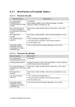
8.1.2
Status Indicator of the Power Supply on the IO
Board
Status indicators
Icon
Status definition and indicators
12V power indicator
12V
Power on, and indicator is on (green), which indicates 12V
output is normal
5V power indicator
5V
Power on, and indicator is on (green), which indicates 5V
output is normal
3.3V power indicator
3.3V
Power on, and indicator is on (green), which indicates 3.3V
output is normal
Reserved indicator
A
The indicator is on when the system is on the reserved status.
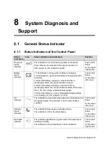
8.1.3
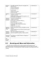
Status of whole machine
The
status of
whole
machine
Status definition and
indicators
To enter the
Patient Info
screen:
To exit the Patient Info screen:
Scanning
status
The power-on status
indicator turns on green,
and the button indicator is
white
Entering or exiting the scanning status by the [Freeze] key
Freezing
status
The power-on status
indicator turns on green,
and the [Freeze] key is
orange
Entering or exiting the freezing status by the [Freeze] key
Standby
status
There are 3V3-STB and
5V_STB of power are
normal, other power are
off
The standby indicator
blinks orange.
1. Press the power switch for a
short time, and then the system
enters into the standby status
by choosing from the status
popped on the screen.
2. If there is no operation for
the time set at first, the system
would enter into the standby
status automatically.
3. The system will enter into
the standby status after 30s if
the control panel is fold.
The system restores to
the freezing status after
restarting by pressing
the power switch for a
short time.
Screen-s
aver
status
The brightness of the
monitor is 0%, and the
backlight of the control
panel is off.
Screen-saver default is
“mindray” showing on the
monitor.
There is no operation for the
time set firstly, and then the
system would enter into the
screen-saver status from the
freezing status automatically.
When you press any
keys on the control
panel, the system would
return to the freezing
status, the brightness
and the backlight of the
control panel both
restore to the previous
Summary of Contents for Z6
Page 2: ......
Page 14: ......
Page 16: ...2 2 Product Specifications Left side 9 4 7 5 6 8 ...
Page 72: ......
Page 119: ...Structure and Assembly Disassembly 7 35 图 7 59 Disassembly of Speaker 8 ...
Page 120: ......
Page 132: ......
Page 142: ......
Page 152: ......
Page 168: ......
Page 171: ...Phantom Usage Illustration B 3 ...
Page 172: ......
Page 173: ...P N 046 010452 00 5 0 ...

