Structure and Assembly/Disassembly
7-23
NOTE:
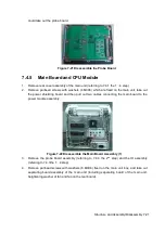
1. The button cell model of the main board PCBA is Lithium 3V220mAh D20*3.2.
2. During assembly, please assemble the main board and fasten with the screws, and
then install the CPU module.
7. Turn the main board, remove the panhead screws with washers M3X6 (4 pcs), and then the
4D board can be removed. (For Z6 VET machine of V05.00.00 (Rev10840) or latter versions)
7.4.6
Top Cover Assembly of Keyboard
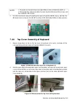
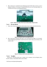
1. Remove plugs fixed on the on the top cover of keyboard (4 for each), and take off the
corresponding panhead screws with washers M3X8 (4 for each).
Figure 7-26 Disassemble the Top Cover of Keyboard (1)
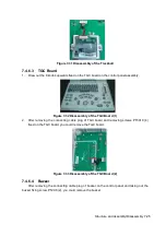
2. Hold the upper edge of the keyboard upper cover assembly, and open up the keyboard upper
cover to the extent till you can remove the screw for fixing the cable connecting the keyboard
and the main unit, as described in the figure, and then pull out the whole keyboard upper
cover assembly.
Figure 7-27 Disassemble the Top Cover of Keyboard (2)
Summary of Contents for Z6
Page 2: ......
Page 14: ......
Page 16: ...2 2 Product Specifications Left side 9 4 7 5 6 8 ...
Page 72: ......
Page 119: ...Structure and Assembly Disassembly 7 35 图 7 59 Disassembly of Speaker 8 ...
Page 120: ......
Page 132: ......
Page 142: ......
Page 152: ......
Page 168: ......
Page 171: ...Phantom Usage Illustration B 3 ...
Page 172: ......
Page 173: ...P N 046 010452 00 5 0 ...


