background image

Overview 

1.4.9Disassembly of the fan

1.  Remove the rear cover;

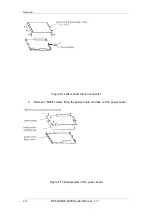
2.  Disconnect the tail board fan connector and remove 4 M3X30 screws, and then 

remove the tail board fan; 

Figure 2-35 Disassembly of the tail board fan

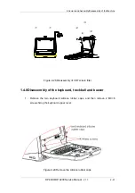
3.  Disconnect the back board fan connector and remove 8 M3X30 screws, and 

then remove the back board fan. 

2-26

DP-3300/DP-3200


Service Manual

V1.1

Summary of Contents for DP-3200

Page 1: ...DP 3300 DP 3200 Digital Ultrasonic Diagnostic Imaging System Service Manual...

Page 2: ......

Page 3: ...ts or patents and does not convey any license under the patent rights of Mindray nor the rights of others Mindray does not assume any liability arising out of any infringements of patents or other rig...

Page 4: ...ray in China and other countries All other trademarks that appear in this manual are used only for editorial purposes without the intention of improperly using them They are the property of their resp...

Page 5: ...ifications and repairs of this product are conducted by Mindray authorized personnel the electrical installation of the relevant room complies with the applicable national and local requirements the p...

Page 6: ...n Policy Return Procedure In the event that it becomes necessary to return this product or part of this product to Mindray the following procedure should be followed 1 Obtain return authorization Cont...

Page 7: ...uth Hi tech Industrial Park Nanshan Shenzhen P R China 518057 Phone 86 755 26582479 26582888 Fax 86 755 26582500 26582501 EC Representative Shanghai International Holding Corp GmbH Europe Address Eiff...

Page 8: ...container Return shipments will not be accepted if the Mindray number is not clearly visible Please provide the model number serial number and a brief description of the reason for return 5 Freight po...

Page 9: ...us injury WARNING Indicates a potentially hazardous situation which if not avoided could result in death or serious injury CAUTION Indicates a potentially hazardous situation which if not avoided may...

Page 10: ...bed in the corresponding section Read and understand these precautions before performing the measurement 5 Data in temporary storage areas such as the CINE memory is deleted when the power supply is t...

Page 11: ...DP 3300 DP 3200 Service Manual V1 1 I...

Page 12: ......

Page 13: ...ACHINE 1 1 2 1 Basic features 1 1 2 2 Basic composition 2 STRUCTURE AND ASSEMBLY DISASSEMBLY OF THE MACHINE 1 1 3 STRUCTURE OF THE COMPLETE MACHINE 1 1 3 1 Appearance view of the main unit 1 1 3 2 Exp...

Page 14: ...r 22 1 4 9 Disassembly of the fan 27 1 4 10 Remove USB extension wire 28 CHAPTER 2 DESCRIPTION OF THE PRINCIPLE 1 2 1 PRINCIPLE OF THE HARDWARE 1 2 1 1 Principle description of the main board 1 2 1 2...

Page 15: ...RIP 3 4 5 IMAGE INTERFERENCE 3 4 6 BACK END CIRCUITS FAULT 4 4 7 OTHER FAULTS 5 CHAPTER 5 MAINTENANCE AND CLEANING 1 5 1 MAINTENANCE TO BE PERFORMED BY USER 1 5 1 1 Cleaning the system 1 5 1 2 Creatin...

Page 16: ......

Page 17: ...of abdomen and obstetrics 1 2Introduction of Complete Machine The DP 3300 3200 system is a digital portable ultrasound diagnostic system which is compact and cost effective The DP 3300 3200 system ca...

Page 18: ...control port 10 USB interface optional 11 Ethernet interface DICOM3 0 optional 12 Self diagnosis performance testing report 1 2 2Basic composition The system consists of transducer transducer board m...

Page 19: ...Structure and Assembly Disassembly of the Machine Figure 1 1 Diagram of the complete machine DP 3300 DP 3200 Service Manual V1 1 1 3...

Page 20: ......

Page 21: ...embly of the Machine Structure and Assembly Disassembly of the Machine 1 3Structure of the Complete Machine 1 3 1Appearance view of the main unit Figure 2 2 Appearance view of the main unit DP 3300 DP...

Page 22: ...901 20 23950 2 3 screen filter 2302 20 34425 1 4 keyboard hook 2302 20 29092 1 5 front cover 2302 20 34401 1 6 anti collision pad of keyboard 2302 20 29091 2 7 rubber cap A of the handle 2302 20 34471...

Page 23: ...066 1 6 2300 20 29067 1 5 A 2300 20 29071 1 3 2300 20 29076 2 2 2302 30 34484 1 5 1 2302 30 34427 1 9 8 7 3 4 1 6 2 Figure 2 4 Exploded view of the keyboard assembly 1 1 3 3 2Composition of the keyboa...

Page 24: ...4 1 5 2302 20 34405 1 1 2 3 4 5 6 Figure 2 5 Exploded view of the keyboard assembly 2 1 3 3 4Composition of the keyboard assembly 2 1 keyboard upper cover 2302 20 34400 1 2 dust plate 2302 20 34423 1...

Page 25: ...embly 1 3 4 1Exploded view of CRT assembly 5 2300 20 29109 1 3 C R T 2300 20 29095 1 1 C R T 2300 21 29149 1 2 C R T 2300 20 29094 1 4 2 2300 20 29108 1 1 2 3 4 5 Figure 2 6 Exploded view of CRT assem...

Page 26: ...d 2302 20 29059 1 4 power board shielding pad 2302 20 29202 1 5 power box lower cover 2302 20 29195 1 6 cover plate of transducer socket 2302 20 34448 2 7 connection board 2302 30 29053 1 8 main unit...

Page 27: ...1 25 transducer board 2302 30 34407 1 26 transducer socket fixed plate 2302 20 29101 1 27 shield spring A 2102 20 16918 4 28 shield spring B 2102 20 17113 4 29 transducer socket fastener 2302 20 2919...

Page 28: ...ber cap Remove the two fixing screws M4x16 and then take out the handle Remove the two fixing screws M4x12 and then take out the winding rack winding rack rubber cap Figure 2 9 Remove the handle and w...

Page 29: ...move the rear cover 2 Disconnect the fan connector of the tail board 3 Remove 8 M3X6 screws fixing the tail board and 2 M3X6 screws fixing the main board 4 Disconnect the power wire connector move the...

Page 30: ...6 screws fixing the rear cover and take out the rear cover Figure 2 12 Disassembly of the cabinet rear cover 1 4 4Disassembly of the power board 1 Remove the assembly of cabinet rear cover 2 Pull out...

Page 31: ...y of the Machine Figure 2 13 Disassembly of the power board 3 Remove 6 M3X6 screws fixing the power box upper cover and open the upper cover 4 Disconnect the fan connector of the power board M DP 3300...

Page 32: ...view Figure 2 14 Disconnect the fan connector 5 Remove 7 M3X8 screws fixing the power board and take out the power board Figure 2 15 Disassembly of the power board 2 12 DP 3300 DP 3200 Service Manual...

Page 33: ...assemblies of the tail board and the back board 2 Remove 3 M3X8 screws fixing the holder of the transducer cable hook and take out the holder Figure 2 16 Remove the holder of the transducer cable hook...

Page 34: ...of the main board and the transducer board 1 Figure 2 18 Disassembly of the main board and the transducer board 2 5 Pull out the assemblies of the main board and the transducer board backward 2 14 DP...

Page 35: ...er board 3 6 Remove 7 M3X6 screws connecting the assemblies of the main board and the transducer board and disassemble the main board Figure 2 20 Disassembly of the main board and the transducer board...

Page 36: ...rd and the transducer board 5 8 Remove 4 M3X6 screws fixing the connection board of the transducer socket and remove the transducer board Figure 2 22 Disassembly of the main board and the transducer b...

Page 37: ...sassemble the rear cover to take out the assemblies of the tail board and the back board 2 Remove 4 PT4X14 screws fixing the front cover Figure 2 23 Remove 4 PT4X14 screws fixing the front cover 3 Dis...

Page 38: ...Overview Figure 2 24 Disconnect the connection wires 4 Remove 8 M3X8 screws fixing CRT assembly and take out CRT Figure 2 25 Remove CRT assembly 2 18 DP 3300 DP 3200 Service Manual V1 1...

Page 39: ...cture and Assembly Disassembly of the Machine 5 Remove CRT adjustment knobs and 4 PT3X8 screws fixing CRT adjustment board and then remove the CRT adjustment board DP 3300 DP 3200 Service Manual V1 1...

Page 40: ...n remove the connection board of the main unit Figure 2 27 Remove the connection board of the main unit 1 4 7Disassembly of CRT screen filter 1 Slide the two screen filter buckles outward and pull the...

Page 41: ...28 Disassembly of CRT screen filter 1 4 8Disassembly of the keyboard trackball and buzzer 1 Remove the two keyboard silicone rubber caps and then remove 2 M3 6 screws fixing the keyboard upper cover F...

Page 42: ...ver by hands forcibly at the positions of arrows Figure 2 30 Disassembly of the keyboard upper cover 3 Disconnect the connection wire connector of the keyboard and remove the keyboard upper cover 2 22...

Page 43: ...achine Figure 2 31 Disassembly of the keyboard upper cover 4 Disconnect the connection wire connector of the trackball remove 4 ST3x14 self threading screws fixing the trackball and remove the trackba...

Page 44: ...erview Figure 2 32 Disassembly of the trackball 5 Pull out keyboard knobs A B C and 6 keyboard toggle switches Figure 2 33 Remove the keyboard knobs and switches 2 24 DP 3300 DP 3200 Service Manual V1...

Page 45: ...ews fixing the keyboard and remove the silicone rubber keys to take out the keyboard PCB and then remove 2 ST2x6 screws fixing the buzzer to take out the buzzer Figure 2 34 Remove the buzzer DP 3300 D...

Page 46: ...tail board fan connector and remove 4 M3X30 screws and then remove the tail board fan Figure 2 35 Disassembly of the tail board fan 3 Disconnect the back board fan connector and remove 8 M3X30 screws...

Page 47: ...fan 1 4 10Remove USB extension wire 1 Disassemble the rear cover the cabinet tail board assembly the cabinet back board assembly and the front cover assembly 2 Remove 7 PT3x8 screws fixing the cabinet...

Page 48: ...semble the cabinet 3 Remove 2 PT3x 8 screws fixing the USB compressor and remove the USB compressor and then take out the USB extension wire Figure 2 38 Remove the USB extension wire 2 28 DP 3300 DP 3...

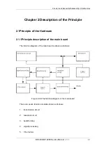
Page 49: ...ciple description of the main board The function diagram of the main board is shown as follows Figure 3 39 The function diagram of the main board There are seven function modules shown as follows 1 tr...

Page 50: ...tion circuit and the high voltage generated by the transmission circuit The conversion among the elements and channels is directly executed by the high voltage isolation circuit rather than the high v...

Page 51: ...ontrolled gain amplifier In addition this dual channel DAC can also generate a voltage controlled signal for controlling the PHV variation and the input signal of the DAC is provided by EP1S10 EP1S10F...

Page 52: ...an also generate the horizontal and vertical synchronization signals for the VGA monitor and the control signal for the video printer The function of the DSC circuit is realized in one FPGA which is t...

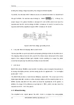
Page 53: ...sound transmission The elements have intrinsic spectrum and changing the spectrum of the excitation signal can change the transmission spectrum i e changing the spectrum of the transmission pulse For...

Page 54: ...ple pulse transmission since the central frequency is determined by the pulse repetition period the high level width of transmission pulse can be adjusted in a bigger range and the transmission weight...

Page 55: ...r To make the echo signal match the monitor the internal circuit structure of the machine is comprised of three parts namely low noise pre amplifier LNP voltage controlled attenuator VCA and programma...

Page 56: ...d for the direct current component of the output signal of the voltage controlled gain amplifier circuit enabling it to couple the direct current level required by the ADC circuit before it enters the...

Page 57: ...the Stratix series made by ALTERA It features 1M gate 10 000 LE 94 blocks of 512bits RAM 60 blocks of 4Kbits RAM one block of 512Kbits RAM and six DSP blocks each DSP block can be configured into one...

Page 58: ...mory function of Cine review and to provide the memory space of 4M 16 bits One piece of SDRAM is adopted to store 64 frame high density images or 128 frame low density images The control logic of the...

Page 59: ...LV25616L 256K 16 is used as buffer in the transform circuit of Vga to Video The THS5641 is used as VGA DAC as well as VIDEO DAC Since the two channel VIDEO signal is to be driven the output of VIDEO D...

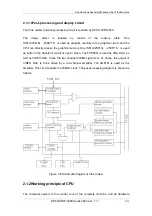
Page 60: ...rs 9 two full duplex serial ports 10 IIC bus 11 parallel I O port 12 system integration module SIM In the 90MHz core frequency the processing capability of the chip 5307 is 75MIPS dhrystone 2 1 testin...

Page 61: ...st be applied The distribution of the 45MHz external frequency clock of CPU is shown below Figure 3 9 CPU system clock distribution 2 1 2 4Voltage detection circuit The voltage detection circuit is de...

Page 62: ...ayer interface 4 NE2000 register grade compatible 5 internal 8K 16 BITS SRAM 6 LOCAL BUS interface seamlessly connecting with MCS51 ISA and 68K 7 MII interface connecting to other physical layers To c...

Page 63: ...s comprised of two parts the real time multitask operating system and system application program and it features as follows 15 Real time 16 Responding to asynchronous events 17 Responding to synchrono...

Page 64: ...management and machine management 2 Manager for booking and releasing information This information releasing manager doesn t generate a sample However it serves as an object in the system managing th...

Page 65: ...uffer which saves the preset data based on the current exam mode 7 Hardware driver The hardware driver object is designed for driving the system hardware It generally builds up its structure based on...

Page 66: ...ructure is FIFO rank TheMailBox This mailbox is used for saving the information with common priority Its data structure is FIFO rank TheMailBox2 This mailbox is used for saving the information with mi...

Page 67: ...em displays the start up screen 6 The system configures other circuit FPGA 7 The system reads out the preset data and based on the preset selects the exam mode and the transducer 8 The front end is in...

Page 68: ...Probe D ata 3 2 2Upgrading operation Each item in the upgrading submenu is used for the upgrading function Perform the upgrading operation based on the different data that are described in the table b...

Page 69: ...is taken as an example to describe the upgrading procedure Put a U disk with UPG upgrading files into a USB interface Click system software a file dialogue box pops up and opens Load Fi l e H el p D r...

Page 70: ...pdate fi ni shed pl ease re pow er Turn off the machine and then after a while turn it on again OK Note After the upgrading finishes for some data it needs to turn off the machine and turn it on again...

Page 71: ...of connection wire of CRT Check the system according to the following chart No display or display abnormality Replace the main board Is the problem resolved The main board s fault CRT s fault No Yes F...

Page 72: ...echo images are missing Replace the transducer and use the same connector Connect different transducer connector Is the problem resolved The transducer s fault The transducer board s fault Yes Yes No...

Page 73: ...ault No Figure 5 49 Solution of black area in the image 4 5Image Interference If it is abnormal in image area such as interference ripples and bright lines etc first verify it is not interference from...

Page 74: ...board s fault Yes Yes No No Replace power board Is the problem resolved Yes The power board s fault The main board s fault No Figure 5 50 Solution of image interference 4 6Back end Circuits Fault If i...

Page 75: ...B fault The cable s fault The main board is abnormal The software doesn t support U disk or the printer Replace USB interface cable Check the main board Use U disk or the printer of specified model 3...

Page 76: ......

Page 77: ...ag to wipe off the dirt on the transducer socket B If it is hard to get rid of the dirt use the rag soaked the mild detergent to wipe off then make the transducer socket air dried 3 Cleaning CRT Use t...

Page 78: ...ing and the rotary ball with clean soft dry cloth or paper Long shaft Bearing Long shaft c Installing the trackball Put the rotary ball back in the trackball and then align the clamping ring click wit...

Page 79: ...r may cause malfunction or degradation of performance 5 1 2Creating a backup copy of the system hard disk To prevent any damage or loss of data stored in the system hard disk users should create a bac...

Page 80: ...current Patient leakage current I Patient leakage current II Patient auxiliary current Mechanical safety The monitor mounting mechanism Control panel Mounting mechanism for the peripheral devices Oth...

Page 81: ...P N 2302 20 34499 V 1 1...

Reviews: