Mincon Rockdrills – “The Driller’s Choice”
Page 4
2.2.4
Operation
Be sure to familiarise yourself with the controls of the machine and work in accordance with the manufacturers
recommendations.
The percussive mechanism begins to operate as the air supply is turned on and when the drill bit is pushed firmly into the
hammer. Excessive thrust pressures are not needed to make it work. The thrust controls on the drill should be adjusted to the
correct pressure and should be readjusted to take account of the weight of any extra tubes added so that the thrust pressure
remains constant and not excessive. Insufficient thrust pressure will make the hammer drill erratically and less efficiently and
cause premature wear to the bit and chuck splines with likely damage to the hammer components and threads.
When the hammer is lifted from the rock face, the drill bit extends from the chuck and the percussive action ceases. Extra air
will pass through the hammer, which can be used to flush the hole clean.
Rotation speeds should not be too high and should be selected to suit drilling conditions and drill bit diameters. High rotation
speeds do not provide fast drilling and can cause premature wear of drill bits, hammers and tubes. Too slow a rotation speed
can cause binding in the borehole and damage to drill bit inserts.
The controls of the drill should be adjusted in order to provide the largest drill chip size with the smoothest rotation and feed
characteristics. Recommended rotation speeds would normally vary between 25 – 35 R.P.M. for most applications.
Where big diameter drill bits are used or when drilling in hard abrasive rocks, slower rotation speeds are recommended.
Conversely, in soft, non-abrasive rock a slightly faster rotation speed may be selected to produce more satisfactory results.
Some ground conditions may cause binding within the hole, with the added risk of the hammer and drill string becoming
jammed. Any excessive pullback forces or high rotation speeds used in an attempt to recover the drill string may generate heat
zones around the hammer, which may alter the metallurgy of the components to cause damage and ultimate failure. A
backreamer sub may help prevent jamming in bad ground conditions and prevent heat damage.
You are strongly advised not
to pour diesel into the hammer as this may create an internal combustive effect and will damage
the hammer and its components. Any heat induced failures are not covered by our terms of warranty.
Before adding drill tubes make sure that the threads are clean and well greased and that there are no contaminants likely to
enter the hammer to cause damage and early wear.
Proper drill guides and break out systems must be used which suit the diameter of the hammer. All tools and spanners used for
the drill bit and break out flats must fit properly.
Make certain that the hammer is stationary when applying spanner or breakout tools. Do not rotate the hammer with a spanner
attached to the drill string unless it is safely captivated within the breakout clamp.
2.3 Servicing
2.3.1
General
Dismantling the Hammer for servicing or to change the bit can be made easier if the chuck threads are regularly greased and
the backhead threads are well greased any time the hammer is opened for servicing. We recommend that a good quality
thread grease be used, and in acidic conditions, we do not recommend copper based greases as this can trigger a galvanic
reaction with corrosive effect to damage the root of the threads and cause failure.
2.3.2
Opening Chuck and Backhead
The threads used in Mincon Hammers are right hand threads. Proper tools and break-out systems should be used at all times
to dismantle DTH hammers, otherwise damage may be caused to the components which could result in eventual failure or
affect the performance of the Hammer. When using Petol wrenches or similar systems, ensure that the wrench is not placed on
the threaded section of the wear sleeve. Petol wrench jaws should be carbide, and in good condition. It is good practice to
2
4
25
50
750
1000
125
1
3
5
150
7.0
14.0
21.
28.0
35.0
42.0
1
2.0
0.5
1.5
2.5
US Pints/Hour
Litres/Hour
A
ir
V
o
lu
m
e
-
CF
M
A
ir
V
o
lu
m
e
–
M
3
/M
IN
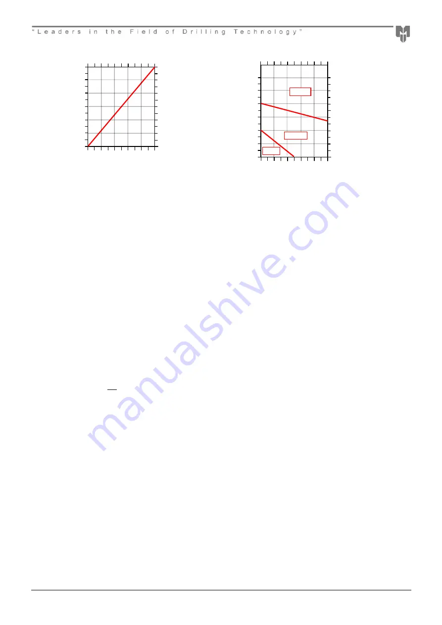
In wet drilling (above 2gpm/8 lpm)
the oil consumption should be
Pressure - PSI
Pressure - Bar
A
m
bi
e
nt
Te
m
pe
ra
tur
e
º
F
A
m
bi
e
nt
Te
m
pe
ra
tur
e
º
C
200
400
0
20
40
60
80
100
300
500
100
-
-6.7
4.4
15.6
26.7
37.8
13.
27.
6.9
20.
34.
120
48.9
-20
-
ISO4
ISO150
ISO32
Summary of Contents for 6DH360
Page 1: ...Mincon 6DH360...


