background image

- 4.2 -

Aplication Functions

The application functions make it possible to modify the printing conditions that have been set for

source data received from the computer. The [FUNCTION] key is used to set up the application

functions.

FUNCTION MENU

Of the menus that are provided for setting printing conditions for the device, the menu for setting up

the device functions is called the function menu. In order to set printing conditions properly, it is

necessary to understand the structure and operation of the function menu.

The function menu consists of four major items - [Set-up], [Maintenance], [Display] and [Media

set]. In this chapter, [Set-up] and [Display] of the function menu are explained. (For “Maintenance”

of the function menu, see Chapter 5 “Maintenance Functions.”)

[SET UP] 

• 

[DISPLAY]

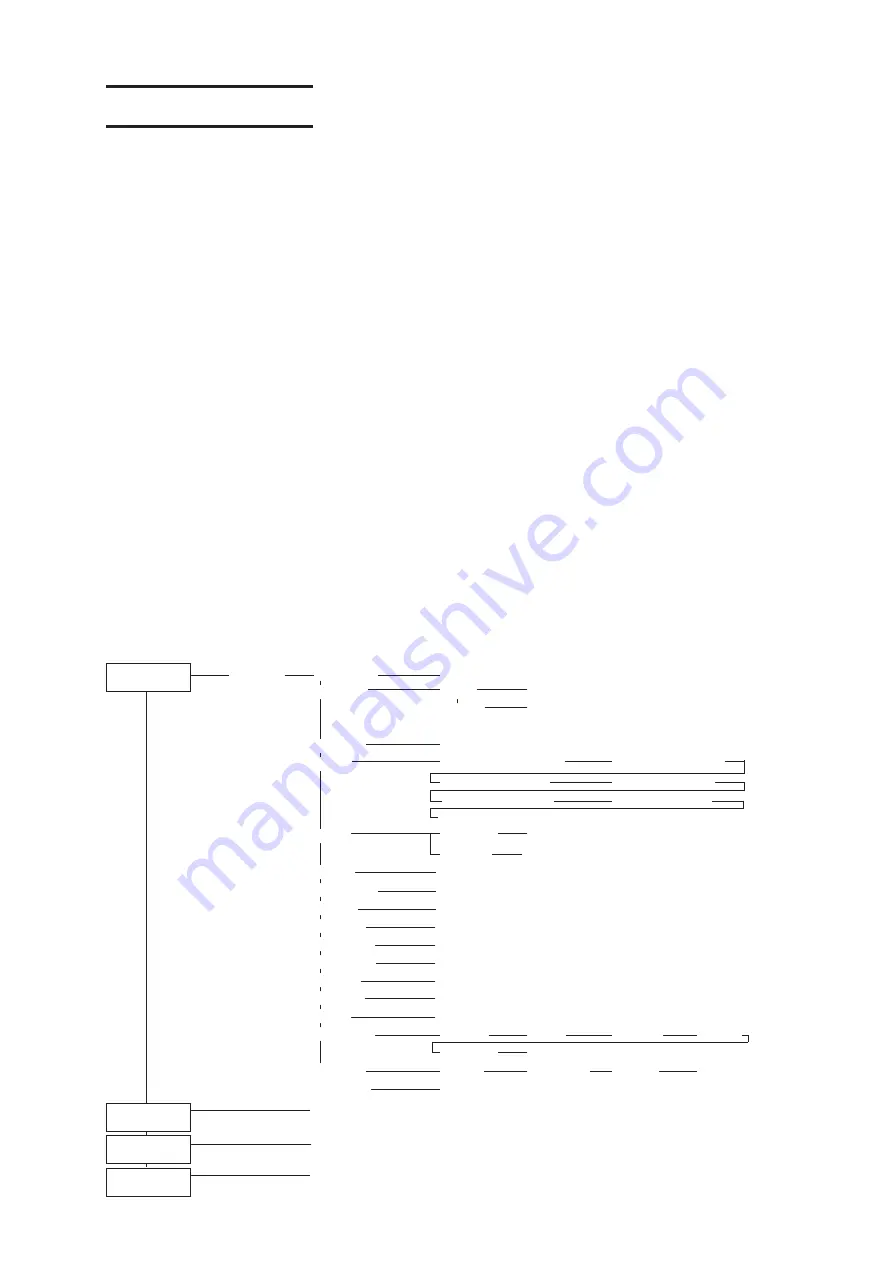
The table, below, shows the tree structure of the function menu.

In order to use the application functions of the device, it is necessary to understand the proper

sequence of key operations.

In Set-up of the function menu, allocate printing methods to be set to Types 1 to 4 before detailed

setting of the individual printing conditions so that you can use the printing conditions registered by

type.

[FUNCTION]

TYPE1 to 4

Media Comp.

-500 to 500

SET UP

Print Mode

Quality

STD, FINE, HIGHspd

Direction

UNI-D, BI-D

Ink Layers

1 to 9

Priority

Media Comp. : HOST, PLOT

PrintMode : HOST, PLOT

InkLayers : HOST, PLOT

Refresh : HOST, PLOT

Belt Wash : HOST, PLOT

Heater. : HOST, PLOT

ANRS : HOST, PLOT

Margin

RightMargin

-9 to 95mm

LeftMargin

-9 to 95mm

Refresh

Level 0 to 3

Counter Limit

Adhesive, Absorb Rlr

mm/inch

inch, mm

AutoClean

OFF, ON

Feeding Dev

OFF, ON

Take-Up Dev

OFF, ON

Spiral Rlr

OFF, ON

Belt Wash

OFF, ON

Heater

LOW, MID, HIGH, ODD

ANRS Setup

Dot check

Interval

Check NG

Cleaning

Retry Count

MediaEnd

ANRS Ctrl

Total NG

Adjoining NG

MissShot

MissShot NG

SetupReset

Reset

[FUNCTION]

See Chapter 5 “Maintenance Functions”.

MAINTENANCE

[FUNCTION]

ENGLISH , JAPANESE


, PORTUGUESE , ITALIANO , ESPANOL , FRANCAIS , DEUTSCH

DISPLAY

[FUNCTION]

Reset

MEDIA SET

Summary of Contents for Textile Jet Tx3-1600

Page 1: ...NEERING CO LTD TKB Gotenyama Building 5 9 41 Kitashinagawa Shinagawa ku Tokyo 141 0001 Japan Phone 81 3 5420 8671 Fax 81 3 5420 8687 URL http www mimaki co jp E mail trading mimaki co jp D201026 OPERA...

Page 2: ......

Page 3: ...t 2005 MIMAKI ENGINEERING Co Ltd All Rights Reserved DISCLAIMER OF WARRANTY THIS LIMITED WARRANTY OF MIMAKI SHALL BE THE SOLE AND EXCLUSIVE WARRANTY AND IS IN LIEU OF ALL OTHER WARRANTIES EXPRESS OR I...

Page 4: ...us laser radiation CDRH REGULATION The Center for Devices and Radiological Health for the U S Food and Drug Administration Implement regulations for laser products The Label shown below indicates comp...

Page 5: ...ation Manual This operation manual describes the operation and maintenance of Model Tx3 1600 Color InkJet Plotter hereinafter referred to as the plotter Please read and fully understand this Operation...

Page 6: ...during printing If a failure is detected this function performs recovery operation recheck etc according to the setting This function enables unattended print operation Applicability of fabric up to 7...

Page 7: ...ic retainer can be used to avoid contact of the fabric and ink head Ditch for penetrated ink Even with printing to a coarse textured fabric the backing fabric is not stained by penetrated ink Removabl...

Page 8: ...t will facilitate the use of the device Example of Pictorial Signs The symbol indicates the case where some phenomenon that re quires a CAUTION sign including DANGER and WARNING signs exists A concret...

Page 9: ...duces smoke and contact a distributor in your district for repair Never repair your device by yourself since it is very dangerous for you to do so Power supply and voltage Be sure to use the device wi...

Page 10: ...beam through a lens or the other optical observation system Handling of the power cable Take care not to damage break or work on the power cable If a heavy matter is placed on the power cable heated o...

Page 11: ...up the head See Cleaning ink heads in chapter 2 Periodic exchange parts There are some parts which must be replaced by service men after Tx3 1600 are in use for 5000 hours from 3000 hours Therefore we...

Page 12: ...e ink cartridge with ink Using any ink type other than the exclusive one can cause a trouble Remember that the user shall be charged for a repair to correct any damage resulting from the use of ink ot...

Page 13: ...d or you may not secure the stabilized plot work CAUTION A place that vibrates Do not install the device at the place that vibrates or you may not secure the stabilized plot work A place full of dust...

Page 14: ...6 Front face 1 6 Rear face 1 7 Inside of rear face 1 8 Side face of main unit 1 8 The blower unit and its vincity 1 9 Names And Functions Of The Parts Under The Front Cover 1 10 Capping station 1 10...

Page 15: ...2 22 Using the fabric retainer 2 23 Adjusting the Pressure Roller Position 2 24 Adjusting the Feeding Tension Bar Weight 2 25 Removing slacks using the curved bar 2 26 Adjusting the number of pieces...

Page 16: ...e drain below the capping Drain Wash 3 20 When the device will not be used for a long time Storage Wash 3 21 Cleaning the bottom surface of the carriage 3 23 Cleaning the flushing box and blower filte...

Page 17: ...ng Setup Conditions List 5 13 Printing HEX Code Of Printing Command Data Dump 5 14 Selecting Ink Head Use Head 5 15 Menu Displayed After The Ink Cartridge Is Installed Ink Filling 5 16 When Replacing...

Page 18: ...e is explained The pages of each chapter are given serial numbers starting from 1 Notes to sentences caution on device operation and hints for effective use of the device are given The item to select...

Page 19: ...lay is shown in characters in a box as shown at right Operate the device according to the explanation of the operation procedure and the content of display on the LCD In this instruction manual each s...

Page 20: ...overy procedure for ink clogging and the cleaning procedure for each section CHAPTER 4 How to Use the Application Functions This chapter describes the application functions of the device such as the f...

Page 21: ...1 2 Moving The Device 1 3 Accessories 1 4 Configuration And Function 1 6 Names And Functions Of The Parts Under The Front Cover 1 10 Operation 1 15 Connecting The Cables 1 18 Switching ON OFF The Powe...

Page 22: ...before assembling the device The place of installation must have space required not only for the device itself but also for printing operation Length Width Height Gross weight 3250 mm 1550 mm 1400 mm...

Page 23: ...the power cable as well as moving installation of the device We should take no responsibility for any troubles caused through the power cable connection by the customer without calling for service Me...

Page 24: ...according to your order Main unit Power cable x 3 Empty fabric core Grounding adapter x 3 with Main unit Fabric core support pipe x 2 Waste ink tank Adjuster foot lower plate x 4 Hand pump Bemcot Ten...

Page 25: ...4 Maintenance oil Wiper cleaning kit Cotton swab x 10 Device driver CD ROM Wiper Gloves Filter for Cleaning tank filter x 20 Rubber glove Indicator Flushing box Guide of Printable Textile Dye ink Fabr...

Page 26: ...the LCD for displaying set items etc 12 Waste ink tank Collects waste ink that has been used for cleaning 13 Ink station Loads ink cartridges or ink pack for ink supply to each head 14 Take up tensio...

Page 27: ...eding belt is stabilized by through the fabric and attaching lapels 9 Feeding tension bar weight Used to adjust the weight of the feeding tension bar 10 Left station cover R Remove the cover when the...

Page 28: ...Heater indicator Indicates operating state of heater Lighting The setting temperature has been reached Blinking Temperature has not been reached to the setting value 2 Heater voltage selector Used fo...

Page 29: ...revent the ink mist by inhaling air inside of the flushing box 3 Blower inlet Connect the power cable for blower 4 Blower power switch Power switch for blower 5 Blower control cable Cable connects to...

Page 30: ...cting it up Capping station The capping station consists of ink caps wipers for cleaning the heads etc Ink Cap It covers the nozzles of print head to prevent from drying up Wiper It is used to clean t...

Page 31: ...e device itself Head height adjustment rod adjustment screw and Head protection sensor When a fabric is set for the first time or replacing a fabric in different thickness it is necessary to adjust th...

Page 32: ...rinting While the printer is not being used keep the pressure roller at the raised position If the pressure roller is left on the belt the roller and belt will adhere making it difficult to separate t...

Page 33: ...detects the printing width Printing with the full width up to 1620mm width is possible by setting the fabric retainer to a position apart from the edge 1620mm width or less The fabric retainer is det...

Page 34: ...ia guide Roll guide cover hand screw Roll guide cover Front roll guide hand screw Front roll guide ANRS check media 2 Rear roll guide hand screw Rear roll guide 1 ANR unit Automatic Nozzle Recovery Un...

Page 35: ...rned on DATA CLEAR key Used to erase the data that has been input to the device REMOTE key It is used to change the operation mode between the REMOTE mode and the LOCAL mode ENTER key Used to input se...

Page 36: ...d below LOCAL mode This is the mode in which the preparations for printing operation are made When the power is switched on and the detection of a fabric is completed the device enters the LOCAL mode...

Page 37: ...the procedure shown below 1 Push the appropriate operation key on the operation panel 2 Select the desired setting item 3 Set up the desired function Operation key Desired setting item Desired functio...

Page 38: ...tion of the interface cable and the power cable IEEE 1394 interface is used Use an IEEE 1394 interface cable to connect the computer and the device together if the computer has IEEE1394 interface The...

Page 39: ...tallation of the device We should take no responsibility for any troubles caused through the power cable connection by the customer without calling for service Heater setting The plotter may be damage...

Page 40: ...ront cover and station cover L R must be closed With the front cover kept open the carriage does not move even when the power is switched on Since the heater indicator displays the operating status it...

Page 41: ...d with the device Turning the power off To turn the power off check first whether there is received data or remaining un output data Also be sure that the head rests at the capping station If the powe...

Page 42: ...ey and display the Ink Level 3 Push the ENTER key and display the Remain ing Fabric length 4 Push the ENTER key and display the fabric width 5 Push the ENTER key and display the remain ing ANRS check...

Page 43: ...error information guidance Press the key to display all currently occurred Error 11 Push the ENTER key and display the Log guidance Press the key to display the counter log of Adhesive BeltWiper and A...

Page 44: ...0355LC LIGHT CYAN SPC 0357LC LIGHT CYAN SPC 0356LC 5 E MAGENTA SPC 0355M MAGENTA SPC 0357M MAGENTA SPC 0356M 6 F LIGHT MAGENTA SPC 0355LM LIGHT MAGENTA SPC 0357LM LIGHT MAGENTA SPC 0356LM 7 G YELLOW S...

Page 45: ...AN SPC 0355C CYAN SPC 0357C 5 6 E F MAGENTA SPC 0355M MAGENTA SPC 0357M 7 8 G H YELLOW SPC 0355Y YELLOW SPC 0357Y NO Disperse dye ink Printing pigment ink 1 2 A B BLACK SPC 0356K BLACK SPC 0350K 3 4 C...

Page 46: ...ink Black Cyan Magenta Polyester Polyurethane Nylon Disp Yellow Light cyan Acetate vinylons and other synthetic Light magenta Gray Blue material Right blue Printing pigment ink Black Cyan Magenta Cot...

Page 47: ...rtridges even if under warranty period If the ink cartridge and ink packs is moved from a cold place to a warm place leave it in the room temperature for three hours or more before using Make sure to...

Page 48: ...rinting pigment ink 3 Press the ENTER key 4 Press the JOG key or to select the number of colors of ink 8 set 8 colors 4 set 4 colors When TPig is selected only 4 set is possible 5 Press the ENTER key...

Page 49: ...ink change register the appropriate ink type for each ink station Refer to Page 1 23 The registered ink type is necessary when checking the printing informa tion and changing the heads used 1 2 3 4 5...

Page 50: ...fabric When using the Leaf the following functions are disabled Feeding Take Up Spiral Rlr Sizes of fabric that can be used Maximum 1650 mm Minimum 200 mm printing width 1620 mm Thickness 7 mm or les...

Page 51: ...rint Item Condition Remarks Width variation Curve when expanded Slack height when expanded on a flat surface Displacement of roll edge Inner diameter of roll Fabric core strength Length of fabric core...

Page 52: ...int side Fabric wrinkle Hardness Tape at up to 3 points or weak adhesion 270mm or less 38kg or less Not specified Not allowed The fabric is twine around the upper part of the peeling roller not greate...

Page 53: ...son with the center extended fabric or the fabric which has slack when the fabric is spread out However the curved bar cannot be used on the fabric which the pre processing is too hard as the fabric w...

Page 54: ...1 34...

Page 55: ...low 2 2 Switching ON OFF The Power Supply 2 3 Front Cover Left And Right Station Cover 2 4 Setting The Fabric To The Plotter 2 5 Using The Fabric Core Support Pipe 2 32 After Setting The Fabric On The...

Page 56: ...e Usingt the feeding tension bar Using the pressure roller Using the spiral roller Using the curved bar Using the fabric edge guide Using the peeling roller Using the take up tension bar Using the hea...

Page 57: ...ont cover and station cover L R must be closed With the front cover kept open the carriage does not move even when the power is switched on Since the heater indicator displays the operating status it...

Page 58: ...ting data is lost Cautions during operation STEP 1 When opening the cover during printing the message will be displayed on the LCD 2 After the completion of data transmission from the computer close t...

Page 59: ...heavy fabric the roll must be set more than 2 people After setting the fabric make sure to check that the head height has been properly adjusted Refer to Page 2 33 STEP 1 Confirm the operation panel...

Page 60: ...ll to the left and right together with the roll holder When the roll position has been settled at the center secure the screw of the left and right roll holders Using the fabric edge as a guide fix th...

Page 61: ...ether the printing side is rolled inward or outward and release the roll 9 Pinch only the center of fabric to lead it Change the fabric lead position according on the fabric type Pinch the center of f...

Page 62: ...t in it When using the wide fabric ravels or threads of the fabric edges may cause getting caught into the fixed knob of the spiral roller In case setting those fabric cut the edges and then set it on...

Page 63: ...another roller whether fabric folded 12 Return the fabric about 200 to 300mm from the pressure roller Make sure that the edge side of the fabric is straight If not straighten it Failure to do so may...

Page 64: ...nd the pres sure roller to the belt and then once put aside the pressure roller 15 Put the fabric on the belt with tension by ad justing loose position outside of right and left hand sides to the tigh...

Page 65: ...aking the curved part of the curved bar into right under 19 Rewind the fabric until the feeding tension bar goes up by 100 mm to the feeding device 20 Select the rotational direction of the feeding de...

Page 66: ...bric and then feed the fabric until it passes the roller by 200 to 300mm During the above operation peel off the fabric by hand Put the fabric on the Peeling roller and then push the JOG key to feed t...

Page 67: ...edge is extremely displaced be sure to align when use it Using the fabric edge guide allows the fabric peeling operation more properly Make sure to use the fabric edge guide when using the narrow wid...

Page 68: ...r and hook the fabric setting bar on the stopper 25 Feed the fabric inside the Lapel bar by using the fabric setting board Take Up Limit error has occurred take up tension bar left in stopper for a wh...

Page 69: ...ess of 10mm or more or a fabric core support pipe on the take up side 28 Pull out the fabric from under the heater and then lead it between the empty fabric core and the lapel bar In case printing inw...

Page 70: ...e to make a roll of fabric This completes fabric setting If you start printing before the leading edge of the fabric reaches the take up device Peeling Error error or Take Up Check Tension error occur...

Page 71: ...abric retainer depend on the fabric width 34 Close the front cover and push the ENTER key MEDIA ROLL LEAF 35 Push the JOG key to detect the roll fabric width Choose ROLL 36 Push the ENTER key If the l...

Page 72: ...xample of fabric setting completion Front Side Back Side Media Curved bar Spiral roller Lapel bar Feeding tention bar Pressure roller Peeling roller Heater Take up tension bar Example of fabric settin...

Page 73: ...o pre vent the fabric from being caught by the head Be sure to make sure this point Since the heater cannot be used effectively be careful of stain of the fabric after printing When setting the fabric...

Page 74: ...MEDIA SET is not displayed 1 Press FUNCTION key 2 Select MEDIA SET by pressing the JOG keys and 3 Press ENTER key 4 Press ENTER key to reset 5 Perform the leaf fabric width detection Press JOG key to...

Page 75: ...eset then perform the leaf fabric width detection FUNCTION SETUP ENT FUNCTION MEDIA SET ENT LOCAL width 1620mm MEDIA SET ROLL LEAF MEDIA SET Capacity 110 m MEDIA SET Capacity 650 m Detecting Media Ple...

Page 76: ...on page 4 17 AUTO Rotates or stops the roll automatically depending on the position of the tension bar Available jog operation and printing MANUAL Rotates the roll con stantly Take Up side ROTATION up...

Page 77: ...re roller on the belt the fabric may rise up In case the pressure part is removed from the fabric retainer make sure to move the central part of the slider onto the fabric edge to detect fabric width...

Page 78: ...he adhesive force has decreased and using a silk material use the High position The above is merely a rough standard Be sure to check the sticking condi tion before setting the position Since the pres...

Page 79: ...required Adjustment is required for such non stretch fabric that cause vertical wrinkles when weights are removed to apply tension such as thin chiffon and voile Add some weights It is recommended th...

Page 80: ...bric Adjust the angle of R position for the vertical direction The R peak position cannot be changed Adjusting the curved bar angle Change the angle of the curved bar according to slacks of the fabric...

Page 81: ...curved bar is located at the standby position 2 Lead the fabric 3 Move the curved bar to the setting position 4 Loosen the setscrew and then set up the R peak position according to the fabric condi ti...

Page 82: ...ller In case setting those fabric cut the edges and then set it onto the device With narrow fabric be sure to set the fabric at the center of the belt In the following cases however the center positio...

Page 83: ...spiral roller shaft up and then remove the roller to avoid falling it down and breaking the device 3 Loosen the hand screw of the both side and then shift the number of piece Refer to the next page fo...

Page 84: ...and then take some fixed pieces out from the bar accord ing to the fabric center position 2 Shift the rest pieces to the left side and then tighten with the hand screw After that remove the right hand...

Page 85: ...set to the take up device it is not necessary to match the width In addition it is not necessary to attach with a handheld sewing machine etc just use the roughly 100mm width fabric attach with a pap...

Page 86: ...2 Fix the core and support pipe with tape 3 Loosen the hand screws of the both side of the roll holders and then remove the large holders with hand screws The space is tight between roll holders Large...

Page 87: ...head height Head Height is a function to set the distance between the fabric surface and head to 3mm STEP 1 Confirm the device is the LOCAL mode 2 Press FUNCTION key 3 Press JOG keys and until the LCD...

Page 88: ...stment rod till it stops moving anymore If the tip of the head height adjustment rod makes contact with the surface of the fabric repeat step 9 a to raise the head c Turn the head height adjustment sc...

Page 89: ...c width detection after initialization Select the fabric by using jog keys according to the fabric has been set 13 The device enters the LOCAL mode after detec tion 14 Perform the PrintAdjust Refer to...

Page 90: ...void fluffing of the fabric surface warp of the fabric edge or waving of the fabric during printing the distance between the head and the printing surface of the fabric can be increased When the dista...

Page 91: ...AL mode 2 Press FUNCTION key 3 Press and key until the display gives the indication MAINTENANCE 4 Press ENTER key 5 Press and key until the display gives the indication PrintAdjust 6 Press ENTER key 7...

Page 92: ...ith PrintAdjust The dot position enables to correct again after entering the correction value once 9 Press ENTER key 10 Repeat Steps 8 and 9 to correct the dot posi tions on Patterns 2 to 7 Select the...

Page 93: ...ead space from the printing fabric The dead space at the front and rear edges of the fabric can be reduced using a guiding fabric Changing the dead space The dead space is resizeable area The effectiv...

Page 94: ...t Wash is executed when jogging in the X direction is performed In this case if a belt cleaning error occurs jogging cannot e performed STEP 1 After the fabric width detection is completed move the ca...

Page 95: ...o use the fabric which width is more than 200mm when execut ing the test draw STEP 1 Make sure the device enters the LOCAL mode 2 Make sure the fabric has set on the belt 3 Press TEST key 4 Press ENTE...

Page 96: ...of the ink head Check the test pattern to determine whether head need cleaning Out put direction R row Print head F row Print head Test pattern Line are not drawn at uniform intervals BLURRED Horizont...

Page 97: ...ink station interior Refer to Page 3 12 STEP 1 Make sure the device enters the LOCAL mode 2 Press CLEANING key 3 Select the ink head to be cleaned by pressing the JOG keys and 4 Display the ink head t...

Page 98: ...int standby screen appears 5 Press ENTER key Enter the printing width by pressing the JOG keys and 6 Press ENTER key Test printing for correction of the fabric feed rate starts 7 When plotting finishe...

Page 99: ...ENTER key 10 Press END key twice and the menu returns to the LOCAL mode Even after starting actual printing the correction value can be changed during printing Refer to Page 2 46 LOCAL width 1620mm T...

Page 100: ...oes not print correction patterns Perform only correction value input operation while checking print data 1 Make sure that the device is the REMOTE mode 2 Press FUNCTION key to confirm the current set...

Page 101: ...before saving it 6 Press ENTER key to return to the REMOTE display The changed setting value is saved The value is to be in effect performing till the turning off Press END key to return to the REMOTE...

Page 102: ...at have been set for the data are dis played For the method of data transmission see the manual for the output attached to the software 5 During the printing During the printing operation the length o...

Page 103: ...carriage and erase the receive data from the device STEP 1 If data is being transmitted from the computer to the device stop the data transmission 2 Press REMOTE key to stop the printing op e r a t i...

Page 104: ...ge 3 6 3 7 and Appendix Supply Parts Belt cleaning by circulating water from the cleaning liquid tank When belt cleaning is performed by circulating cleaning water cleaning water becomes dirty immedia...

Page 105: ...wice and the menu returns to the LOCAL mode 9 Close the sewer valve of the tank 10 Fill the cleaning liquid tank with about 20 liters of water When the belt cleaning is performed with water circulatio...

Page 106: ...e side of the fabric the reverse side may be stained In this case wind the supplied emery cloth 150 in a spiral configuration around the surface of the peeling roller and then fix both edges with an a...

Page 107: ...he displayed new cartridge number into the ink station 3 When the amount of ink completely runs out during printing The amount of indicated ink has completely run out Install a new ink cartridge into...

Page 108: ...ff while the plotter is engaged in printing the head may fail to be stored in the capping station If the head is left without capped for an extended period of time the nozzle will be clogged with dust...

Page 109: ...essary or periodically so as to use the device for a long time while keeping its printing accuracy Table of contents Routine Maintenance 3 2 Cleaning The Station Interior 3 11 Cleaning The Y Main Guid...

Page 110: ...rom entering inside the device If the inner part of the device becomes wet electric shock hazards and breakage of the device can result Conduct maintenance works after turning off the power switch and...

Page 111: ...ange water every day when belt cleaning is being performed with water circula tion The dirty water is pumped up with attached hand pump and then pour clean water into the tank When belt cleaning is be...

Page 112: ...g by executing Count Reset Wash Filter on P 5 20 1 Open the tank and then loosen the setscrew 2 Replace the filter with a new one and then tighten the setscrew 3 Insert the hose in the tank without sl...

Page 113: ...Remove the cap of the strainer unit 4 Wash the mesh filter with tap water until the mesh is no longer clogged Also run water through the pipe to wash it It is not necessary to disassemble the whole me...

Page 114: ...Make sure to apply new adhesive immediately Refer to Page 5 4 The adhesive was applied unevenly Dust thread and tiny fleck are not able to remove from the belt even if Washing belt function has perfo...

Page 115: ...e the warning by executing Count Reset Absorb Rlr on P 5 20 1 Turn off the power to the device Before cleaning the water absorption roller put a fabric like waste cloth etc on the floor to avoid being...

Page 116: ...he roller to avoid break the sponge c Sponge the water off from the roller with Bemcot after cleaning Do not twist the roller to avoid break the sponge d Dry the roller out well 5 Fix the water absorp...

Page 117: ...is dripping wait until it stops dripping Make sure to wear rubber gloves for replacement STEP 1 Pull out the hose from the waste ink tank When pulling out the waste ink tank hold the opening of the wa...

Page 118: ...replaced filter then reuse the filter The mist fan filter is sold separately When changing the filter contact your dealer or Mimaki sales office STEP 1 Pull the mist fan filter holder out of the mist...

Page 119: ...to dry easily causing nozzle clogging and bending We recommend frequent cleaning Types of carriage cleaning Station Carriage Out WiperExchange Flushing Box exchange Nozzle Clean Drain Wash Storage Was...

Page 120: ...ean the two wipers at a time The front side of each wiper is made of felt and the rear side is made of rubber Do not rub the felt side with a swab Instead press the swab against the felt side surface...

Page 121: ...r to Page 3 12 Station Maint Sel CarriageOut Station Maint Sel CarriageOut LOCAL width 1620mm FUNCTION SETUP ENT FUNCTION MAINTENANCE ENT MAINTENANCE Station ent Prepare two sets of wipers When printi...

Page 122: ...th a swab from the rubber mounted around the cap 10 Press ENTER key after taking the chain off from the cover and closing the station cover R 11 The device enters the fabric width detection MEDIA SET...

Page 123: ...lso clean the wiper shaft STEP 1 Put the device into the MAINTENANCE mode Refer to Page 3 13 2 Press ENTER key 3 Press ENTER key to select Station 4 Press ENTER key to select CarriageOut The carriage...

Page 124: ...3 16 7 Take the chain off from the cover and close the station cover R then press ENTER key 8 The device enters the fabric width detection Initialize Station Maint Completed ent MEDIA SET ROLL LEAF...

Page 125: ...ace Wiper is displayed on the LCD replace the wipers with new ones The message Replace Wiper is displayed while the device is in operation or when the device power is switched on When the message is d...

Page 126: ...a new wiper It can cause the nozzle clogged Insert the wiper so that its felt side surface is placed on the left as viewed from your position 9 Clean the wiper guide shaft using a swab or cloth If dir...

Page 127: ...ting time 8 Press the JOG key or to set the expo sure time 1 99 minutes Set the time to expose the head to the cleaning liquid during capping 9 Press the ENTER key to perform initialization Initializa...

Page 128: ...r moves to the front and the carriage moves to the maintenance position Suction starts Suction for 10 seconds and a rest for 10 seconds continues succes sively 6 Fill the cap with cleaning liquid usin...

Page 129: ...sure time 1 99 minutes 9 Press the ENTER key to perform initialization Initialization is performed and the head is capped The progress of exposure is displayed 10 Pressing the END key finishes the ope...

Page 130: ...ith cleaning liquid using a drop per Repeat until the ink drain is clean 15 Pressing the END key finishes the operation and performs suction for 30 seconds 16 Initialize the device The device enters t...

Page 131: ...the device 6 Open the station cover L Chain the station cover Refer to Page 3 12 7 Using the supplied swab with water remove ink adhered at the bottom surface of the car riage around the head Never ru...

Page 132: ...ct Flushing Box unless the flushing box is to be really changed The number of operations that is counted in the Device will be reset Cleaning the flushing box 1 Put the device into the MAINTENANCE mod...

Page 133: ...flushing box and wash the flushing box and filter When the Ink blot of sponge is heavy the flushing box get weaker of absorption In case when you find the waste ink on the belt retainer make sure to c...

Page 134: ...x after washing shortly dry the box out well The filter is an option When changing the filter contact your dealer or Mimaki sales office Make sure to wear rubber gloves for replacement STEP 1 Turn OFF...

Page 135: ...er is to be really changed The number of wiper operations that is counted in the Device will be reset STEP 1 Put the device into the MAINTENANCE mode Refer to Page 3 13 2 Press ENTER key 3 Press and k...

Page 136: ...cation ANR Unit 4 Press ENTER key 5 Select Media Set then press ENTER key 6 Replace the media a Open the right station cover and then remove the knob screw of the ANR unit Chain the station cover Refe...

Page 137: ...hand screw remove the Roll guide plate and then remove empty fabric core f Set a new ANRS check media Outside is the printing side of the ANRS checkmedia g Attach the roll guide plate again and then f...

Page 138: ...e empty fabric core using an adhesive tape Set the media so that flatly without slack or wrinkle on the print side of the media 1 If there is a slack or wrinkle set it again It may cause check media j...

Page 139: ...enter the length of the attached media ANRS check media length is 100 meter SPC 0383 9 Press ENTER key and the device enters the fabric width detection ANR Unit Maint Remains 100 m Initialize ANR Uni...

Page 140: ...Ten sion Bar is locked 5 Remove fabric in case its on the belt 6 Make sure to be the tension bar at the lowest position and press the ENTER key 7 Make sure that there is no fabric on the belt and the...

Page 141: ...R key 14 Enter the number of the belt rotation by press ing jog keys and 15 Press ENTER key Drying of the belt starts The remaining number of rotations is displayed 16 Press END key twice and the devi...

Page 142: ...3 34...

Page 143: ...plication functions whereby you can set printing conditions on the device side and put the de vice into operation By using the application functions you can set printing conditions appropriate to data...

Page 144: ...e it is necessary to understand the proper sequence of key operations In Set up of the function menu allocate printing methods to be set to Types 1 to 4 before detailed setting of the individual print...

Page 145: ...nu mode must be either the LOCAL mode or the FUNCTION mode Check also that the mode displayed on the LCD is either LOCAL or FUNCTION Refer to Page 1 16 Setting the display language Set the language in...

Page 146: ...that the mode is LOCAL mode 2 Press FUNCTION key 3 Press ENTER key 4 Select any of Types 1 through 4 by pressing the JOG keys and There are four types which you can select Type 1 Type 2 Type 3 Type 4...

Page 147: ...ality Printing direction Direction This function sets the direction of printing The device prints an image while moving the carriage right and left By setting the direction of printing it is possible...

Page 148: ...6 Press ENTER key 7 Set a printing direction by pressing the JOG keys and There are two printing direction from which you can select one UNI D BI D 8 Press ENTER key 9 Press END key twice and the men...

Page 149: ...ric adhesive force fixation force is weak ened expansion and contraction may cause a rise STEP 1 Select a type Refer to Page 4 4 Here select Type 1 2 Press ENTER key 3 Set a Ink Layers by pressing the...

Page 150: ...operation is performed with priority given the device Priority needs to be specified for each of the following items Media Comp Print Mode Ink Layers Refresh Belt Wash Heater ANRS STEP 1 Select a type...

Page 151: ...OT 14 Press ENTER key 15 Select the Heater that is given a priority using the and key Here select PLOT 16 Press ENTER key 17 Select the ANRS that is given a priority using the and key Here select PLOT...

Page 152: ...bric retainer Printing with the full width is possible by setting the fabric retainer apart from the edge of the fabric STEP 1 Select a type Refer to Page 4 4 Here select Type 1 2 Press ENTER key 3 Pr...

Page 153: ...ow LEVEL 1 Frequency of refreshing is normal LEVEL 2 Frequency of refreshing is slightly high LEVEL 3 Frequency of refreshing is high STEP 1 Select a type Refer to Page 4 4 Here select Type 1 2 Press...

Page 154: ...e for the setting the message won t be indicated STEP 1 Select a type Refer to Page 4 4 Here select Type 1 2 Press ENTER key 3 Press and key until the display gives the indication Count Limit 4 Press...

Page 155: ...0 meter in increments of 1 meter unit is available Initial value is 0 meter The period limit is 500 meter In case it has not entered a value for the setting the message won t be indicated 12 Press ENT...

Page 156: ...Numerics are expressed in millimeters inch Numerics are expressed in inches STEP 1 Select a type Refer to Page 4 4 Here select Type 1 2 Press ENTER key 3 Press and key until the display gives the indi...

Page 157: ...he head is not cleaned automatically STEP 1 Select a type Refer to Page 4 4 Here select Type 1 2 Press ENTER key 3 Press and key until the display gives the indication AutoClean 4 Press ENTER key 5 Se...

Page 158: ...unit is not enabled STEP 1 Select a type Refer to Page 4 4 Here select Type 1 2 Press ENTER key 3 Press and key until the display gives the indication Feeding 4 Press ENTER key 5 Set a Feeding by pres...

Page 159: ...e take up device is not enabled STEP 1 Select a type Refer to Page 4 4 Here select Type 1 2 Press ENTER key 3 Press and key until the display gives the indication Take Up 4 Press ENTER key 5 Set a Tak...

Page 160: ...oller is not enabled STEP 1 Select a type Refer to Page 4 4 Here select Type 1 2 Press ENTER key 3 Press and key until the display gives the indication Spiral Rlr 4 Press ENTER key 5 Set a Spiral Rlr...

Page 161: ...until the display gives the indication Belt Wash 4 Press ENTER key 5 Set a Belt Wash by pressing the JOG keys and Here select ON 6 Press ENTER key 7 Press END key twice and the menu returns to the LOC...

Page 162: ...OW about 80 C 176 F The heater surface temperature reaches about 145C with the HIGH setting When setting the fabric to the take up device do not touch the heater to avoid burn injury 1 Select a type R...

Page 163: ...7 Set a Interval by pressing the JOG keys and Set the unit meter or inch for the dot check interval 8 Press ENTER key 9 JOG keys and to select the measures in case that nozzle clogging or deflection...

Page 164: ...cleaning when the ANR unit has found the nozzle clogging after cleaning Cleaning setting enable to change the method when Check NG setting is AUTO only Refer to Page 4 21 step 9 14 Press ENTER key 15...

Page 165: ...mbers start from the left facing the print head 18 Press the JOG key or to select the color number to set With 4 color select from 1 4 19 Press the ENTER key Pressing the END key twice returns the men...

Page 166: ...ncrete case Totally 8 nozzle clogging has detected The printing operation is to be stopped for the set value is 5 Measures should be changed according to the settings in the step 9 of the ANRS Setup R...

Page 167: ...g judges the position as NG this NG is added to Total NG at procedure 5 LEVEL0 The setting judges as good even if large parts of dots deflected LEVEL1 The setting judges as good with some parts of dot...

Page 168: ...l plotter stop the operating and execute the nozzle cleaning The illustration in the right is an example of 10 nozzle clogging has detected when tolerance level is set to level 1 At this time MissShot...

Page 169: ...ct a type Refer to Page 4 4 Here select Type 1 2 Press ENTER key 3 Press and key until the display gives the indication Setup Reset 4 Press ENTER key 5 Press ENTER key The current printing conditions...

Page 170: ...4 28...

Page 171: ...ft out of operation for a long period of time Table of contents Maintenance Of The Device 5 2 Before Starting Maintenance 5 3 When The Fabric Adhesive Force Is Weakened Belt 5 4 Drawing Setup Conditio...

Page 172: ...just Pattern TYPE1 to 7 Ink Change Ink Filling Select Head Count Reset Wash Filter Belt Wiper Adhesive Absorb Rlr Information Version ANR Chk Unit Serial number FUNCTION See Chapter 2 HOW TO USE THE B...

Page 173: ...opera tion on the operation panel You have to understand how to invoke the desired maintenance function to carry out maintenance STEP 1 Make sure that the device is in the LOCAL mode When the REMOTE...

Page 174: ...Be sure to set up the appropriate air moving system in case of applying adhesive in the closed room or a room with bad ventilation In case using adhesive comply strictly with the Ordinance on the Prev...

Page 175: ...at the Feed Tension Bar is at its low est position 6 Make sure that there is no fabric on the belt and then press the ENTER key 7 Move the fabric edge guide to both ends and fix it 8 Put aside the pre...

Page 176: ...through the belt If kerosene or diesel mixed with cleaning liquid it declines the adhesive force when printing with belt cleaning Therefore if adhesive force suddenly declined after the adhesive repl...

Page 177: ...prevent it from becoming dry 15 Press END key to stop belt transport 16 Remove the doctor and then clean adhesive dust etc adhering to the rubber using Kero sene and cloths 17 Press and key to send ou...

Page 178: ...e using cloths 21 Wipe off the remaining oil and fat using cloths contained with ethanol to clean the belt sur face 22 Press ENTER key to reset the adhesive counter and be ended the operation Or press...

Page 179: ...solvent poisoning When using commercial adhesive be sure to check the compatibility of the solvent component with the material of the belt of this device In this case contact your dealer or Mimaki sa...

Page 180: ...guide to both ends and fix it 11 Drop adhesive 150 to 200cc uniformly to the backside of the doctor 12 Press ENTER key then rolling the belt Press and key to send out the belt while adjusting the belt...

Page 181: ...the entire belt surface increase the belt speed Press and key to increase the belt speed up to about 50 to 60 mm s 14 Drop all the remaining adhesive Make sure that adhesive dropped through the half t...

Page 182: ...s ENTER key and then operate the belt with a belt speed of about 10 mm s 18 Leave the device while operating for 2 to 3 hours Make sure that adhesive has dried 19 Press ENTER key to reset the adhesive...

Page 183: ...replaced 4 VERSION Indicates the version of the firmware and memory capacity of the device 5 PARAMETER Used for service persons for maintenance STEP 1 Make sure the fabric has set on the belt 2 Put t...

Page 184: ...ly DATA DUMP automatically feeds line according to the size of fabric used STEP 1 Make sure the fabric has set on the belt 2 Put the device into the MAINTENANCE mode Refer to Page 5 3 3 Press ENTER ke...

Page 185: ...t the device into the MAINTENANCE mode Refer to Page 5 3 2 Press ENTER key 3 Press and key until the display gives the indication USE HEAD 4 Press ENTER key 5 Press and JOG key to select the ink head...

Page 186: ...ink other than the genuine MIMAKI brand ones For ink replacement head cleaning liquid is required STEP 1 Put the device into the MAINTENANCE mode Refer to Page 5 3 2 Press ENTER key 3 Press and key u...

Page 187: ...g liquid cartridge error and perform cleaning 16 Suction of the cleaning liquid starts 17 Wash the tube mid tank and damper with cleaning liquid 18 Remove the cleaning liquid cartridge from the lower...

Page 188: ...enters the ink filling mode 28 Press the JOG key up or down to select the type of ink 29 Press the ENTER key The screen for select ing ink color mode appears 30 Press the JOG key up or down to select...

Page 189: ...ing filling time is less than 1 s the display changes 36 When filling finishes the vacuum is released The device returns to the LOCAL mode When cleaning finishes during ink replacement filling is perf...

Page 190: ...ter Belt Wiper Adhesive Absorb Rlr 6 Press ENTER key 7 Press ENTER key to execute the initialization After the initialization the LCD returns to Counter Reset 8 Press END key twice the menu returns to...

Page 191: ...s ENTER key 5 Press ENTER key to select Version Firmware version is indicated Firmware version is indicated when the ANR unit setting has been selected ON it may gives ANR unit version as well Press J...

Page 192: ...5 22...

Page 193: ...ures to be taken in the case where an abnormal phenomenon arises on the device and where an error message is given on the display Table of contents Before Taking A Phenomenon As A Sign Of Failue 6 2 F...

Page 194: ...fabric has been set improperly Has the power cable been connected to the device and the receptacle No Is the correct interface cable used Has the interface cable been securely connected in position I...

Page 195: ...r loose compared with the gumming portion at both edges With the fabric used is the gumming portion at both edges loose Is the paper core bending Use a pre processed cloth which suits the ink Do not u...

Page 196: ...color heads do not properly overlap Displacement is observed between from to right and from left to right printing Coloring differs in spite of the same fabric and pre processing data Wrinkles occur...

Page 197: ...ng You should advice to the pre processing vender to adsjut pre processing to the grain White horizontal line appears as different length depending on the place appeared Cascade strips show up at the...

Page 198: ...basis However it is recommended to replace the ink cartridge of which number is shown on the LCD with a new one And close the ink station cover Attach the ink cartridge s corresponding with the numbe...

Page 199: ...over Printing will be enabled by pushing the REMOTE Then the error message will not appear until the power is re turned on It is recommended however to replace the wiper with a new one as soon as poss...

Page 200: ...ontact your local distributor to call for service Attach the running flushing box Cleaning the running flushing box or draining the waste ink In case the filter has been dirt clean it Refer to Page 3...

Page 201: ...p Time to change the rewinding motor Time to change the winding motor Time to change the red LED Time to change the blue LED Peeling sensor light intensity have been decreased The device can be used c...

Page 202: ...d The maintenance control command is faulty Check the output setting of the host computer A RIP from other than Mimaki was used Turn off the power to the device an turn it on after a while If the same...

Page 203: ...rtain that no error has arisen on the host computer side Turn off the power to the device and turn it on after a while If the same error message appears again on the LCD contact your local distributor...

Page 204: ...t your dealer or Mimaki sales offices In case pressing the END key not to disable the ANR unit function the error message indicated and then turns the device off automatically System shut down Contact...

Page 205: ...ctive nn Mid tank number Turn off the power to the device and turn it on after a while If the same error message appears again on the LCD contact your local distributor to call for service ERROR 141 I...

Page 206: ...6 14...

Page 207: ...x describes the specifications and components the device function menu structure Table of contents Basics Specifications A 2 Specification For Ink A 4 Supply Parts A 5 Position Of The Warning Label A...

Page 208: ...color Acid dye ink for 8 color printing Acid dye ink for 4 color printing Reactive dye ink for 8 color printing Reactive dye ink for 4 color printing Disperse dye ink for 8 color printing Disperse dy...

Page 209: ...nd Safety Standard FCC ClassA CEmarking CBreport UL60950 Laser sensor Laser Sensor Unit Class I Laser Product Maximum output 0 35mW Pulse Duration 25 s Wave length 650nm Laser medium A Ga nP Power Mai...

Page 210: ...dge SPC 0357OR SPC 0393OR Red ink cartridge SPC 0357R SPC 0393R Golden yellow ink cartridge SPC 0357GY SPC 0393GY Color Black ink cartridge SPC 0356K Disperse dye ink Cyan ink cartridge SPC 0356C Mage...

Page 211: ...ridge SPC 0259 220cc Cartridge Flushing box SPC 0390 1 piece Blower filter SPC 0391 1 piece Flushing mist blower filter Mist filter SPC 0419 4 pieces Mist fan filter Maintenance oil SPC 0364 100 cc Y...

Page 212: ...warning labels Be sure to fully understand the warning given on the labels In the case where any of the warning label has become so soiled that the warning message is illegible or has come off purchas...

Page 213: ...231789745990253 Media Remains m Media Width mm Head Height mm ENTER REMOTE TYPE m ENTER ENTER ENTER Guidance InkType Acid Ink Color 8 Ver1 00 MRL lF Ver1 00 ANRS ENTER ENTER ANR Check Media Check UpTo...

Page 214: ...E AutoClean OFF ENTER TYPE mm inch ent TYPE mm inch mm ENTER mm inch TYPE Refresh Level1 TYPE Margin ent TYPE RightMargin 0mm 9 to 95mm TYPE LeftMargin 0mm ENTER ENTER 9 to 95mm FUNCTION v FUNCTION v...

Page 215: ...ut ent ENTER ENTER Main Guide Maint Completed ent MAINTENANCE Station ent ENTER ENTER Carriage Out Completed ent MAINTENANCE Belt ent Lower The Feed Tension Bar ENTER Remove Media Press ENT Key ENTER...

Page 216: ...n View Version MAIN Ver1 00 I F Ver1 00 ANRS Ver1 00 Wash Filter Belt Wiper Adhesive Absorb Rlr MAINTENANCE Ink Change ent ENTER ENTER Remove Cartridge 12345678ABCDEFGH Ink Change Start ent Washing 1...

Page 217: ......

Page 218: ...PrintedinJapan MIMAKI ENGINEERING Co Ltd 2005 EA TM...

Reviews: