background image

- 18 -

Assembling drier fan Unit

1.

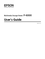
Attach the drier fan stay R/L to the front panel of

the plotter using 4 screws.

2.

Attach the drier fan unit to the fan stay using 2

supporting point screws.
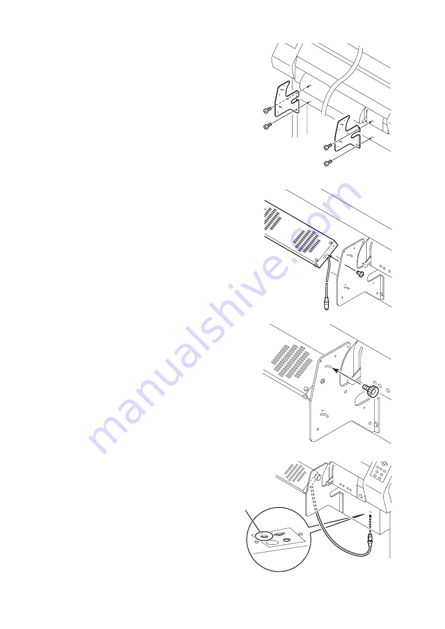
3.

Attach 2 knob screws.

4.

Connect  the drier fan unit cable to the connector at

the underside of the bottom.

For drier fan unit

Summary of Contents for JV3-160SP

Page 1: ...the ink cartridge 8 Where to Install the Device 9 Unpacking and Assembling 10 Assembling the pedestals and the device 10 Mounting the protection cover for 440cc ink cartridges 15 Assembling Rear Exha...

Page 2: ...litate the use of the device Indicates the reference page for related contents Example of pictorial signs The symbol indicates the case where some phenomenon that requires a CAUTION sign including DAN...

Page 3: ...gloves since you may get ink in your eyes If you have swallowed the ink by mistake keep quiet and immediately consult a docto r Do not swallow what you have thrown up Then contact the Poison Control...

Page 4: ...down of the device WARNING Do not use the device in damp places Avoid damp environments when putting the device into service Do not splash water onto the device High humidity or water will give rise t...

Page 5: ...ich temperature and humidity vary by a great margin Use the device under the following environment Operating environment 15 to 30 C 35 to 65 Rh A place exposed to direct air blow from air conditioner...

Page 6: ...against dust It is strongly recommended to use the device in a room that is not dusty See Chapter 4 Maintenance functions Keep the front cover held closed also when the device is not engaged in print...

Page 7: ...od of time has passed after opening the cartridge tank printing quality would be poor Be sure to store ink cartridges in a cold and dark place Never replenishes the ink cartridge with ink Using any in...

Page 8: ...for any damage caused by the use of the ink cartridge replenished with ink Using any ink type other than the exclusive one can cause a trouble Remember that the user shall be charged for a repair to...

Page 9: ...bling the device The place of installation must have space required not only for the device itself but also for plotting operation Model Width Depth Height Gross weight JV3 160SP 2660 mm 750 mm 1240 m...

Page 10: ...ain unit on your feet 1 Lift down the carton which contains the exhaust plotter and legs 2 Remove the four screws which fix the packing legs and packing pads Take the plotter out of the carton togethe...

Page 11: ...empo rarily The stay has vertical and horizontal aspects The side of the leg with a ditch is the outside Use the hexagonal wrench 5 Lock the four stoppers of the leg 6 Hold the handles of the plotter...

Page 12: ...he interface connectors The plotter is very heavy Be careful not to drop it 8 Fix the plotter and stay to the leg Fix the plotter to the leg using four screws Fasten the screws which fix the stay to t...

Page 13: ...and detach the right and left handles 11 Remove the four screws which fix the take up device to the plotter Then attach the take up device to the stay 12 Connect the cable of the take up device to the...

Page 14: ...tank bracket to the plotter 14 Attach the waste ink tank tray with four screws 15 Attach the waste ink tank 16 Open the front cover and then remove the sponges Remove the two screws and then remove th...

Page 15: ...knobs at side of the ink station Keep the knobs for mounting the 440cartridge base 3 Attach the ink name plate on the 440 cartridge base Fix it with two knobs that removed in procedure1 4 Mount the 44...

Page 16: ...idge base Insert the protection cover between the 440 car tridge base and the screws that fixed temporarily in procedure5 Tighten the screws to mount the protection cover 7 Mount the protection cover...

Page 17: ...ightward or leftward depending on the exhaust outlet ventilation 2 Fix the exhaust hose using hose band Lead the opposite end of the hose outdoors 3 Attach binding band for fixing the exhaust hose to...

Page 18: ...y R L to the front panel of the plotter using 4 screws 2 Attach the drier fan unit to the fan stay using 2 supporting point screws 3 Attach 2 knob screws 4 Connect the drier fan unit cable to the conn...

Page 19: ...eading the exhaust hose to the left P 24 1 Fix the exhaust fan to the take up device shaft using one knob and two screws Attach the exhaust fan to fit the setup orientation left right of the duct hose...

Page 20: ...haust cover R to the drier fan stay R and leg stay using 3 screws 4 Attach the exhaust cover L to the drier fan stay L and leg stay using 3 screws 5 Attach the exhaust cover stay to the exhaust cover...

Page 21: ...e spacing between the right and left fixing plates are too narrow loosen the two bolts fixing the roll screen locking plate Then put the both right and left exhaust covers apart aand attach the roll s...

Page 22: ...is needed to detach the roll screen Be careful not to lose the pin 9 Lead the exhaust hose under the exhaust cover Attach it to the exhaust fan using hose bands Be sure to lead the exhaust hose outdo...

Page 23: ...23 11 During plotting hang the screen bar to the exhaust cover...

Page 24: ...of the exhaust fan 1 Remove the two screws 2 Change the direction of the exhaust fan so that the exhaust hose will come to the left side Fix the exhaust fan with two screws 3 Lead the exhaust hose un...

Page 25: ...reen If the elasticity has been lost wind the spring again as shown below 1 Pull the end of the screen about 12 inches out 2 Give 17 counterclockwise turns to the knob at the right end of the screen w...

Page 26: ...rom the factory the voltage is set to 220 V for safety Connecting the plotter to a 220V power supply with the voltage selec tor set to 110V may damage to it Connecting the plotter to a 100 120V power...

Page 27: ...E 1394 interface cable to connect the computer and the device together It is possible to use an IEEE 1284 interface cable for connection between the computer and the device In this case however the da...

Page 28: ...ower cable into an approriately grounded re ceptacle If not there is a fear of arising electric shock hazards and damage to the device Be sure to turn off the power switch of the device in prior to th...

Page 29: ...rn ON the main power of the plotter Set the power switch on the rear panel of the plotter to the I side The main power is turned ON Close the front cover If the front cover is open the plotter does no...

Page 30: ...y and press the ENTER key Sol Solvent ink M Sol Mild solvent ink SS2 Sol SS2 ink Solvent ink 2 If an ink cartridge has already been set in the unit the message on the right will appear Remove the ink...

Page 31: ...le the device is engaged in plotting the head may fail to be retracted in the capping station If the head is left without capped for an extended period of time the nozzle will be clogged with dust If...

Page 32: ...rtridges 8 pcs Goggle Waste ink tank Rear duct hose Hose band Duct Screws 3 pcs Waste ink tank bracket Waste ink tank tray Binding bands 2 pcs Bolts 8 pcs screws 2 pcs screws 4 pcs For legs Power cabl...

Page 33: ...lution RS Cleaning solution RS kit for maintenance Screws 4 pcs for Drier fan Knob screws 2 pcs for Drier fan Supporting point screws 2 pcs for Drier fan unit 440 cartridges base 2 plate Protection co...

Page 34: ...Printed in Japan D200926 1 10 11112004 MIMAKI ENGINEERING Co Ltd 2004...

Reviews: