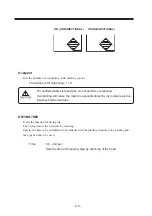
- 5.6 -
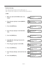
When medium thickness is changed [Print Adjust]
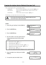
When the head height is adjusted, be sure to correct the dot positions.
This function corrects the dot positions to ensure that the accurate plotting result is obtained.
The dot positions are corrected by comparing the ink dropping positions on each of the seven test
patterns between the two plotting directions.
Always perform Print Adjust (dot position correction) whenever the head height is changed.
STEPS:
1.
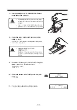
Set a sheet of paper, use 297mm x 210mm or
larger size with the long side set horizontally,
and set the Origin.
2.
Select the [Print Adjust].
3.
Press the [ENTER] key.
4.
Press the [ENTER] key.
Plotting of the test patterns for the correction of dot position
starts. There are seven types of test patterns that are plotted.
5.
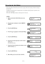
Press the XY [ ] or [ ] keys to correct the dot
position of pattern 1.
The seven test patterns that are output are sequentially
named [PATTERN 1] to [PATTERN 7].
Select the correct dot positions on [PATTERN 1] pressing the
XY [ ] or [ ] keys.
Select the dot positions that make a straight line on the test
pattern in the two plotting directions.
• If the pattern correction value for straight lines is
not within -15 t15, adjust the head height
and then correct it again with [Print Adjust].
MAINTENANCE
Print Adjust
< ent >
∗
∗
Printing
∗
∗
Please Wait
Print Adjust
Pattern
: ent
Print Adjust
Pattern1
= 4.0
Select the dot positions 4.0 that
make a straight line on the test
pattern in two plotting direction.
Summary of Contents for DM3-1810S
Page 2: ......
Page 20: ... xvi ...
Page 34: ... 1 14 ...
Page 76: ... 3 20 ...
Page 112: ... 6 10 ...
Page 131: ... A 19 TYPE Refresh Level3 TYPE mm inch mm X Level0 Level3 X inch Function flowchart ...
Page 141: ... A 29 MAIN Ver1 00 I F Ver Function flowchart ...
Page 144: ...D201258 1 10 30032007 ...
Page 145: ......
Page 146: ...PrintedinJapan MIMAKI ENGINEERING Co Ltd FW 5 10 NH ...

