background image

- 6 -

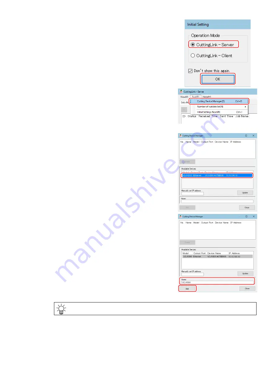
(2) On the [Initial Setting] screen, select [CuttingLink-Server],

and then click [OK].

• [Data Management] is displayed.

(3) From the [Tool] menu, select [Cutting Device Manager].

(4) Select UCJV300/150, CJV300 Plus series in [Available

Devices].

(5) Enter [Name], and then click [Add].

• UCJV300/150, CJV300 Plus series is added to the list.

(6) Click [Close].

4. Register CuttingLink with RasterLink.

• Make sure that CuttingLink is running.

(1) Start RasterLink.

• CuttingLink is started automatically when PC starts.

Summary of Contents for CJV300 Plus

Page 1: ...also apply to the case even if MIMAKI ENGINEERING CO LTD had been notified of the possibility of arising damages in advance As an example we shall not be liable for any loss of the media made using th...

Page 2: ...ck up the data of CuttingLink Server 14 Migrate CuttingLink Server 14 1 Reset initial setting on CuttingLink Server PC before migration 14 2 Configure Server on CuttingLink Server PC to be migrated 14...

Page 3: ...int data and the cut data separately ID Cut Operation Flow System configuration RasterLink ID Data Print ID Data Adjusting the image quality and colors and so on register marks detection Automatically...

Page 4: ...with CuttingLink P 5 4 Register CuttingLink with RasterLink P 6 1 Set the media onto UCJV300 150 CJV300 Plus series P 8 2 Check if the media margin is sufficient P 8 1 Start RasterLink P 9 2 Read the...

Page 5: ...n download the upgraded version of the installer from the Mimaki website http mimaki com Software to receive image data edit data with various functions and send plot data to the printer RasterLink6Pl...

Page 6: ...ct Cutting Device Manager 4 Select UCJV300 150 CJV300 Plus series in Available Devices 5 Enter Name and then click Add UCJV300 150 CJV300 Plus series is added to the list 6 Click Close 4 Register Cutt...

Page 7: ...ction destination The Connection destination setting screen is displayed 5 On the Connection destination setting screen select this my computer and then click OK The Connection destination setting scr...

Page 8: ...width of the media is equal to or larger than Entire image width including the reg ister mark right 15 mm left 15 mm If any of the front left right margin is insufficient the media end may be mistake...

Page 9: ...the Sample file If there is no sample file use the data created in step 2 1 Select the following files on the Select file name to print screen and click Open For Windows CD drive EN English ID Cut_Sam...

Page 10: ...ister marks and ID data are added to the data 7 Click the Execution icon in the function icon list on the right side of the screen 8 Select RIP Print or Immediate Print 9 Click Start 10 Data with ID w...

Page 11: ...s the ENTER key This switches to the mark detection mode 3 Press the keys to move the luminous point of the LED pointer to the center of the reg ister mark 4 Press the ENTER key The register mark is d...

Page 12: ...th CuttingLink Is CuttingLink Server PC properly regis tered with RasterLink Confirm the following contents On the RasterLink Environments menu Option Communication tab is the CuttingLink Server name...

Page 13: ...Is the ID cut setting correct in UCJV300 150 CJV300 Plus series Check the following contents on the oper ation panel Is CUTTING MARK DETECTION FORM and SIZE the same as the print register mark data S...

Page 14: ...d click the OK button 3 Exit CuttingLink 2 Configure Server on CuttingLink Server PC to be migrated 1 Install and start CuttingLink After restarting the PC after installation CuttingLink will be start...

Page 15: ...50 CJV300 Plus series and set it to CuttingLink Server P 5 Install CuttingLink or later 2 Install CuttingLink on the PC connecting the sixth UCJV300 150 CJV300 Plus series and set it to CuttingLink Cl...

Page 16: ...s cut twice For data of Adobe Illustrator 9 or later to which a transparent effect has been applied when Print Cut is executed in RasterLink cut data may be cut twice In such a case change the setting...

Page 17: ...utput ID cut without creating and recognizing register marks with FineCut Data will be sent automatically to RasterLink 2 Select the data read with RasterLink and click the General Print icon in the f...

Page 18: ...t 4 Select Location of register mark Individual Register marks and ID data are added for each data Whole Register marks and ID data are added to enclose all copied data 5 Offset is set when Whole is s...

Page 19: ...DIR DEFAULT 0 cm 5 cm to the machine width Configure the detection width for the scanning direction The register mark is detected while scanning is performed bidi rectionally at the set detection widt...

Page 20: ...ng direction detect the register mark manually When per forming the auto cut function a function to automatically cut multiple types of regis ter marks data automatically set the media setting directi...

Page 21: ...MEMO...

Page 22: ...D203243 16 17082021 2017 MIMAKI ENGINEERING CO LTD All rights reserved MM...

Reviews: